Powertrain for aircraft in runways
- Search and list out the total weight of various types of aircrafts.
Ans:-
An aircraft's gross weight is limited by several weight restrictions in order to avoid overloading its structure or to avoid unacceptable performance or handling qualities while in operation. Aircraft gross weight limits are established during an aircraft's design and certification period and are laid down in the aircraft's type certificate and manufacturer specification documents. The absolute maximum weight capabilities of a given aircraft are referred to as the structural weight limits. The structural weight limits are based on aircraft maximum structural capability and define the envelope for the CG charts (both maximum weight and CG limits). An aircraft's structural weight capability is typically a function of when the aircraft was manufactured, and in some cases, old aircraft can have their structural weight capability increased by structural modifications.
|
Type |
MTOW [kg] |
MLW [tons] |
||
|
640,000 |
591.7 |
Heavy |
Super |
|
|
589,670 |
Heavy |
Super |
||
|
575,000 |
394 |
Super |
Super |
|
|
447,700 |
346.091 |
Heavy |
Heavy |
|
|
443,613 |
306.175 |
Heavy |
Heavy |
|
|
412,770 |
295.742 |
Heavy |
Heavy |
|
|
Antonov An-124-100M |
405,060 |
330 |
Heavy |
Heavy |
|
396,900 |
295.742 |
Heavy |
Heavy |
|
|
381,000 |
288.417 |
Heavy |
Heavy |
|
|
377,840 |
285.700 |
Heavy |
Heavy |
|
|
377,840 |
260.320 |
Heavy |
Heavy |
|
|
371,950 |
240 |
Heavy |
Heavy |
|
|
367,400 |
256 |
Heavy |
Heavy |
|
|
347,800 |
260.816 |
Heavy |
Heavy |
|
|
351,800 |
251.29 |
Heavy |
Heavy |
|
|
347,450 |
223.168 |
Heavy |
Heavy |
|
|
340,200 |
265.300 |
Heavy |
Heavy |
|
|
308,000 |
233.5 |
Heavy |
Heavy |
|
|
299,370 |
237.683 |
Heavy |
Heavy |
|
|
297,550 |
213.00 |
Heavy |
Heavy |
Here, MTOW = Maximum take-off weight, MLW = Maximum landing weight, TOR = Take-off run (SL, ISA+15°, MTOW), LR = Landing run (SL, ISA+15°, MLW)
Maximum design taxi weight (MDTW):-
The maximum design taxi weight (also known as the maximum design ramp weight (MDRW)) is the maximum weight certificated for aircraft maneuvering on the ground (taxiing or towing) as limited by aircraft strength and airworthiness requirements.
Maximum design takeoff weight (MDTOW)
Is the maximum certificated design weight when the brakes are released for takeoff and is the greatest weight for which compliance with the relevant structural and engineering requirements has been demonstrated by the manufacturer.
Maximum design landing weight (MDLW)
The maximum certificated design weight at which the aircraft meets the appropriate landing certification requirements. It generally depends on the landing gear strength or the landing impact loads on certain parts of the wing structure. The MDLW must not exceed the MDTOW. The maximum landing weight is typically designed for 10 feet per second (600 feet per minute) sink rate at touch down with no structural damage.
Authorised weight limits
Aircraft authorized gross weight limits (also referred to as certified weight limits) are laid down in the aircraft flight manuals (AFM) and/or associated certificate of airworthiness (C of A). The authorized or permitted limits may be equal to or lower than the structural design weight limits.
The authorized weight limits that can legally be used by an operator or airline are those listed in the AFM and the weight and balance manual. The authorised (or certified) weight limits are chosen by the customer/airline and they are referred to as the "purchased weights". An operator may purchase a certified weight below the maximum design weights because many of the airport operating fees are based on the aircraft AFM maximum allowable weight values. An aircraft purchase price is, typically, a function of the certified weight purchased.
Maximum weights established, for each aircraft, by design and certification must not be exceeded during aircraft operation (ramp or taxying, takeoff, en-route flight, approach, and landing) and during aircraft loading (zero fuel conditions, center of gravity position, and weight distribution). Weights could be restricted on some type of aircraft depending on the aircraft handling requirements; for example aerobatic aircraft, where certain aerobatic manoeuvres can only be executed with a limited gross weight.
Maximum taxi weight (MTW):-
The maximum taxi weight (MTW) (also known as the maximum ramp weight (MRW) is the maximum weight authorized for maneuvering (taxiing or towing) an aircraft on the ground as limited by aircraft strength and airworthiness requirements. It includes the weight of taxi and run-up fuel for the engines and the APU. It is greater than the maximum takeoff weight due to the fuel that will be burned during the taxi and runup operations. The difference between the maximum taxi/ramp weight and the maximum take-off weight (maximum taxi fuel allowance) depends on the size of the aircraft, the number of engines, APU operation, and engines/APU fuel consumption, and is typically assumed for 10 to 15 minutes allowance of taxi and run-up operations.
Maximum takeoff weight (MTOW):-
The maximum takeoff weight (also known as the maximum brake-release weight) is the maximum weight authorised at brake release for takeoff, or at the start of the takeoff roll. The maximum takeoff weight is always less than the maximum taxi/ramp weight to allow for fuel burned during taxi by the engines and the APU. In operation, the maximum weight for takeoff may be limited to values less than the maximum takeoff weight due to aircraft performance, environmental conditions, airfield characteristics (takeoff field length, altitude), maximum tire speed and brake energy, obstacle clearances, and/or en route and landing weight requirements.
Maximum landing weight (MLW):-
The maximum weight authorised for normal landing of an aircraft. The MLW must not exceed the MTOW. The operation landing weight may be limited to a weight lower than the Maximum Landing Weight by the most restrictive.
2. Is there any difference between ground speed and air speed?
Ans:- Yes There is difference between ground speed and air speed, it is define as below
Wind Speed:-
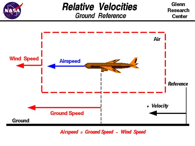
For a reference point picked on the ground, the air moves relative to the reference point at the wind speed. Notice that the wind speed is a vector quantity and has both a magnitude and a direction. Direction is important. A 20 mph wind from the west is different from a 20 mph wind from the east. The wind has components in all three primary directions (north-south, east-west, and up-down). In this figure, we are considering only velocities along the aircraft's flight path. A positive velocity is defined to be in the direction of the aircraft's motion. We are neglecting cross winds, which occur perpendicular to the flight path but parallel to the ground, and updrafts and downdrafts, which occur perpendicular to the ground.
Ground Speed:-
For a reference point picked on the ground, the aircraft moves relative to the reference point at the ground speed. Ground speed is also a vector quantity so a comparison of the ground speed to the wind speed must be done according to rules for vector comparisons.
3. Why is it not recommended to use aircraft engine power to move it on the ground at Airport?
Ans:- Movement of large aircraft about the airport, flight line, and hangar is usually accomplished by towing with a tow tractor (sometimes called a “tug”). In the case of small aircraft, some moving is accomplished by hand pushing on the correct areas of the aircraft. Aircraft may also be taxied about the flight line but usually only by certain qualified personnel.
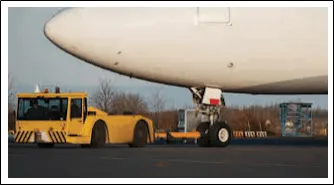
Although many aircraft are capable of moving themselves backwards on the ground using reverse thrust (a procedure referred to as a power back), the resulting jet blast or prop wash might cause damage to the terminal building or equipment. Engines close to the ground may also blow sand and debris forward and then suck them into the engine, causing damage to the engine. A pushback is therefore the preferred method to move the aircraft away from the gate.
Following are the reasons to use Towing vehicle instead of aircraft engine:-
- The jet blast from the engines can damage the terminal building and nearby equipment.
- It can even throw away people standing nearby. Engines can blow sand and debris. Engines can suck in sand and debris which can cause serious damage to the engine.
- It is easier for the truck driver to see the surroundings better than the pilot sitting in the cockpit with limited windows.
- The pushback truck driver knows the airport better than the pilot. The plane engines are very loud. This noise can add up substantially when multiple planes are moving around the airport. It won't be a pleasant experience for people sitting inside the terminal, as most people don't even like the sound of powerful motor-bikes.
- It saves fuel. Virgin Atlantic had proposed a new system in which the pushback trucks will push the plane all the way to the runway to save fuel and reduce impact on nearby environment.
4. How an aircraft is pushed to runway when its ready to take off?
Ans:- The aircraft is pushed to runway using TAXIING.
Taxiing (rarely spelled taxying) is the movement of an aircraft on the ground, under its own power, in contrast to towing or push-back where the aircraft is moved by a tug. The aircraft usually moves on wheels, but the term also includes aircraft with skis or floats (for water-based travel).
An airplane uses taxiways to taxi from one place on an airport to another; for example, when moving from a hangar to the runway. The term "taxiing" is not used for the accelerating run along a runway prior to takeoff, or the decelerating run immediately after landing, which are called the takeoff roll and landing rollout, respectively.
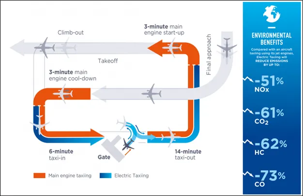
Electric Taxing:-
With the electric taxiing system, an aircraft would be more autonomous and able to reverse and depart its stand more quickly, without relying on ground services and infrastructure. This solution would help improve traffic flows on the apron and at gates, improve flight punctuality and gain precious minutes on the ground, thereby contributing to maximizing the capacity of airports.
Control During Taxing:-
Steering is achieved by turning a nose wheel or tail wheel/rudder; the pilot controls the direction travelled with their feet. Larger jet aircraft have a tiller wheel on the left side of the cockpit that acts as a steering wheel allowing the nosewheel to be turned hydraulically. Braking is controlled by differential toe or heel brakes. Not all aircraft have steerable wheels, and in some cases steering is solely by means of differential braking (all Van's aircraft for instance) or solely by means of the rudder (including all floatplanes).
5. Learn about take off power, tyre design, rolling resistance, tyre pressure, brake forces when landing.
Ans:-
- Take off power:- Takeoff is the phase of flight in which an aerospace vehicle leaves the ground and becomes airborne.
Take off performance can be predicted using a simple measure of the acceleration of the aircraft along the runway based on force equilibrium.
The forces involved will be,
T – Thrust of propulsion system pushing aircraft along runway.
D – Aerodynamic Drag of vehicle resisting the aircraft motion.
F – Rolling resistance friction due to the contact of wheels or skids on the ground.
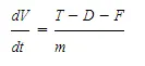
During take-off run the imbalance in these forces will produce an acceleration along the runway.
where dV/dt is the acceleration along the runway and m is the mass of the vehicle.
Rotation Velocity:-
The procedure for take-off will be that the vehicle will accelerate until it reaches a safe initial flying speed. The pilot can then rotate the vehicle to an attitude to produce climb lift and it will ascend from the ground. The determination of this safe flying speed or rotation speed, VR, is a critical factor in determining take-off performance.
Take-off rules vary slightly depending on the aircraft category. Small commuter aircraft should be considered as meeting FAR 23 rules, transport category aircraft should comply with FAR 25 rules.
Small Plane:- For safety reasons VR is usually determined as being
1.1 × VSTALL or 1.05 × VMIN CONTROL
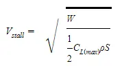
which ever is greater. Stall speed, VSTALL, is the lowest speed that the aircraft can be flown before the airflow starts to separate from wings as the angle of attack becomes too great. The wing is assumed in this case to be in take-off configuration or "clean".
It can be calculated based on knowledge of the aircraft take-off configuration and hence the maximum achievable lift coefficient CL(max). As shown in the previous section , to maintain level flight the lift produced must equal the weight, hence the stall speed can be calculated as,
Minimum control speed, VMC is a more complex calculation and requires knowledge of the stall characteristics of the tailplane and elevator. For conventional aircraft there is only a small difference between VR calculations based on stall speed or minimum control speed.
As well as rotation speed there are other safety considerations as shown in the following Figure.
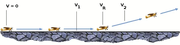
V1- Abort decision speed. Below this speed the take-off can be safely aborted. After this there will not be sufficient runway length to allow the aircraft to decelerate to a stop.
V2 – Safe climb speed. V2 must be no less than 1.2 * Vstall. Below this speed aircraft cannot attain sufficient climb rate.
Design of Aircraft Tyre:-
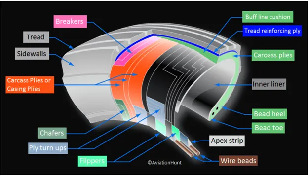
An aircraft tyre is constructed for the purpose it serves.
- They support the weight of an aircraft while it is on the ground.
- It also provides the necessary traction for braking and stopping of an aero plane.
- Tyre also helps to absorb the shock of landing and provide cushioning the roughness of takeoff, roll-out, and taxi operations.
Unlike an automobile or truck tire, it does not have to carry a load for a long period of continuous operation. However, an aircraft tyre absorbs the high impact loads of landing, and also it’s operating at high speeds for a short time when required.
Retreading – Retreading is methods of restoring a worn tyre by renewing the tread area or by renewing the tread area plus one or both sidewalls. Repairs are included in the tyre retreading process.
Load Rating – Load rating is the maximum permissible load at a specified inflation pressure.
Ply Rating – Ply Rating is used to identify the maximum recommended load rating and inflation pressure for a specified tyre. It is an index of tyre strength.
Speed Rating – The speed rating is the maximum takeoff speed to which the tyre has been tested.
Skid Depth – Skid depth is the distance between the tread surface and the deepest groove as measured in the mould.
Aircraft tyres must have an approved speed and load rating and have sufficient clearance when retracted through landing gear to allow for tyre growth. Tyre growth is the increase in the size of the tyre due to centrifugal forces at high speed.
Tubeless tyres are more advantageous over tube-type. There is no longer the use of tube-type tyre in recent aviation. Nowadays all airliners are using tubeless tyres. Tubeless that are meant to be used without a tube has the word TUBELESS on the sidewall of the tyre.
Almost all airliners are using Radial tyre. Bias is an older design, and it’s mainly used for road vehicles. Radial tyres have the word RADIAL on the sidewall. Radial tires are more expensive than bias-ply tyres. Radial tires are in demand because of their lower life cycle cost and long term value.
Chines are also called deflectors. Chine tyre used on the nose wheel of aircraft, specially fuselage-mounted jet engines. It diverts runway water away from the engine inlets.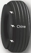
Chines are circumferential protrusions that are moulded into the sidewall of nose tyres that deflect water sideways to help reduce excess water ingestion into the engines. Tyres may have chines on one or both sides, depending on the number of nose tyres on the aircraft.
Tyre Pressure:
The pressure generally is very high in an aircraft tire to reduce the rolling resistance and to withstand the weight. Usually it will be around 200 to 300 psi of pressure and they change based on the type of the aircraft. Tests of airliner aircraft tyres have shown that they are able to sustain pressures of maximum 800 psi. Aircraft tyres are usually inflated with nitrogen to minimize expansion and contraction from extreme changes in ambient temperature and pressure experienced during flight.
Rolling resistance:-
When you press down on the accelerator in your vehicle, you are essentially transferring energy—in the form of gas or electricity, depending on your automobile, through the engine and other systems in your vehicle. That results in your tires turning and enough momentum being built up to move your automobile. To accomplish this, though, your vehicle must overcome a lot of different factors that can make it resistant to forward movement.
Tire rolling resistance is the energy that your vehicle needs to send to your tires to maintain movement at a consistent speed over a surface. In other words, it is the effort required to keep a tire rolling. The main contributor to rolling resistance is the process known as hysteresis. Hysteresis is essentially the energy loss that occurs as a tire rolls through its footprint. The energy loss must be overcome by the vehicle’s engine, which results in wasted fuel.
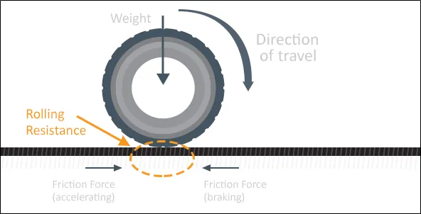
The rolling resistance can be expressed as
Fr = c W (1)
where
Fr = rolling resistance or rolling friction (N, lbf)
c = rolling resistance coefficient - dimensionless (coefficient of rolling friction - CRF)
W = m ag
= normal force - or weight - of the body (N, lbf)
m = mass of body (kg, lb)
ag = acceleration of gravity (9.81 m/s2, 32.174 ft/s2)
The rolling resistance can alternatively be expressed as
Fr = cl W / r (2)
where
cl = rolling resistance coefficient - dimension length (coefficient of rolling friction) (mm, in)
r = radius of wheel (mm, in)
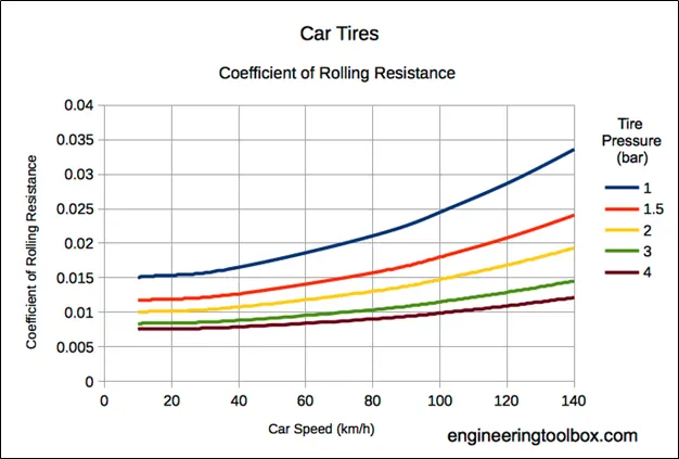
Rolling resistance of Car tyre:-
6. With necessary assumptions, calculate the force and power required to push / pull an aircraft by a towing vehicle.
Ans:- Total force working on Plane:- Fd+Frr+Fr
Fd:- Drag force
Frr:- Rolling Resistance Force
Fr:- Friction force
We know,
Drag force Fd= 0.5*rho*V2*Cd*A
Where rho:- Air density
V=velocity of plain
Cd:- drag coefficient
A:- Frontal Area of plain
Rolling resistance force Frr= c*m*g
Where, C= coefficient of rolling resistance
M=mass of plain
G=acceleration due to gravity
Friction force Frr= Urr*g*a
Where, Urr= coefficient of Friction
M=mass of plain
G=acceleration due to gravity
For calculating Aircraft we will have following assumption:-
Mass:- 640 Ton
Velocity while Pulling/Pushing: - 10 Km/h
Rolling Resistance Coefficient: - 0.02
Coefficient of Aero drag Coeff:- 0.01
Frontal Area:- 100 m2
Coefficient of friction:- 0.01
By using these equation we will calculate the force require to tow the airplane for different velocity:-
close all;
clear all;
clc;

%Assumption for calculation
M=580590            %Mass of Plain
c= 0.03             %Rolling Resistance Coefficient
g= 9.81             %Acceleration due to gravity
Urr= 0.003          %Friction coeff
Cd=0.026            %Coefficeint of Aerodynamic drag
A= 20               %Frontal area of plain
V=linspace(0,5,20)  %Velocity of plain while Towing
rho=1.25            % Air density


%Calculation of forces

Fd=0.5*rho*(V.^2)*A*Cd;
Fr=Urr*M*g;

F=(Fd+Fr/1000).*V

plot(V,F)
title('Power require by Towing vehicle');
xlabel('time (s)');
ylabel('Force (Kw)');
Syntax Explanation:-
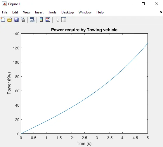
In this program we are calculating the power require by towing vehicle to push or pull the aircraft.
For first 17 line, we giving assumption as a input for the calculation of power. Then we are calculating aerodynamic force, rolling resistance force, friction force.
As we can see, power requirement is not constant as the aerodynamic force is proportional to squar of velocity.
Max power require by Towing vehicle:- 187 Kw.
Result:-
7.Design an electric powertrain with type of motor, it's power rating, and energy requirement to fulfill aircraft towing application. Estimate the duty cycle range to control the aircraft speed from zero to highest. Make all required assumptions. Prepare a table of assumed parameters. Draw a block diagram of powertrain.
Ans:-
|
S.No |
Assumed Parameters |
Assumed Values |
|
Weight of the Aircraft |
580590 kg |
|
|
2. |
Weight of the Towing Tractor |
50000 kg |
|
3. |
Rolling resistance coefficient of aircraft |
0.03 |
|
4. |
Rolling resistance coefficient of towing tractor |
0.001 |
|
5. |
The velocity of the Aircraft while Towing |
5 m/s |
|
6. |
Density of Air medium (rho) |
1.225 Kg/mA3 |
|
7. |
The Frontal area of the Aircraft |
100 m A 2 |
|
8. |
The coefficient of Drag of the Aircraft |
0.01 |
|
9. |
Towing tractor Gear ratio "G" (for high Torque output) |
1 1 |
|
1 0. |
Towing Tractor tyre radius "r" |
0.635 m |
|
1 1 . |
Operational time of the Towing for one cycle |
0.33 Hour |
|
1 2. |
The Battery armature voltage |
420 v |
|
1 3. |
The Battery armature current |
420 A |
|
14. |
The motor terminal voltage for full power output |
650 V @ motor terminals |
|
1 5. |
Power converters used |
Bidirectional DC - DC Boost converter |
|
1 6. |
The maximum duty ratio for achieving full power |
70% |
Assuming the operational time of the Towing truck is around 20 minutes for one cycle
20 minutes = 0.33 Hour
Energy (KWh) = Power (KW) * Time (h) = 187*0.33
Energy (KWh) = 61.71 KWh
Therefore the battery must be able to store the energy of 61.71 KWh and should deliver the energy throughout the run time in order for the motor to produce the 1.45 KNm of torque instantaneously. Thus the storage of energy in batteries with high performance ultracapacitors are selected to fulfill the required power delivery.
Motor Selection:
Here we have selected a BrushlessDC Motor type that has a power rating of 187 KW and with the gear ratio and the transmission it should be able to deliver 1.45 KN.m of torque instantaneously.
The Battery armature voltage (V) = 420V
The Battery armature current (A) = 420A
For getting the maximum power output from the motor (187 KW), the voltage applied to the motor terminals must be 700V (Assume) at the motor's positivp and negative terminals.
Power Converters:
Here we use a DC-DC Boost converter to upscale the voltage level from the battery to the required level so that when supplied to the motor we can get the desired power output from the motor.The bidirectional DC-DC converters find applications in places where battery charging, regenerative braking, and backup power are required.The power flow in a bidirectional converter is usually from a low voltage end such as a battery or a supercapacitor to a high voltage side and is referred to as boost operation.During regenerative braking, the power flows back to the low voltage bus to recharge the battery. As a backup power system, the bidirectional DC-DC converter facilitates the safe operation of the vehicle when ICES or electric drives fail to drive the motor.The boost converter converts the 420V of the armature voltage to a high voltage level of 900 V.
Speed control of the vehicle:
The electric vehicle uses power from the battery source to drive the motor and then further to drive the wheels in order to move the vehicle.The speed and torque generated from the motor is very important to drive the vehicle as per the Driver's desire.lf we connect the battery directly to the motor the motor will spin with a speed and torque characteristics which will be based on the full power of the battery voltage.We does not require full power in all the driving conditions so we need to adopt a power controller between the battery and the motor so that the motor speed may be controlled by the driver to drive the vehicle as desired. For controlling the vehicle power we use the soft switching operation technique here. The amount of power can be controlled by changing the duty cycle value.Considering the losses we take 70 % of the duty cycle to deliver the maximum power of the motor
Motor terminal voltage = Armature voltage * Duty cycle = 900 * 0.7
With 70% Duty Cycle the Voltage at Motor Terminals = 630 V , Which gives the full power with all the gearings, instantaneously.Thus by varying the Duty Cycle value the speed of the vehicle is controlled.