Project 1
- Q) Design of DC-DC converter
Ans:-
DC-DC converters have several applications in electrical industry, they can be employed for varied DC voltage usages and stabilization or the control of DC voltage of a battery or it can be a component of a complex converter to control the intermediate or output voltages. Due to their switching property included in their structure, DC-DC converters have a non-linear behavior and their controlling design is accompanied by complexities. But by employing the average method it is possible to approximate the system by linear system and exploiting linear control methods. Controlling of Buck converters by the method of Linear Quadratic Regulator (LQR). This method is employed for controlling Buck converter and improving its dynamic functioning, but determining the LQR controlling matrices is very difficult.
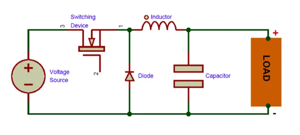
Buck converter has a wide application in the electrical industry and power systems and specifically, it can supply the voltage for a direct current consumer. Buck is one input and multiple-output in structure with a non-linear property due to its switching behavior, but at the same time when the switch is on and off its behavior is linear. Therefore, by employing the averaging method, it is possible to exchange a non-linear system with a linear one. Many of the methods are centered on the isolation of the system variables and PI controller design. Some control methods have defined the subject of control based on pole placement. One of the other control methods is the use of the feedback stage in DC converter control. Another control method is the feedback loop control. Another one is the use of LQR method in the control of Buck converter
Components used in Converter:-
Semiconductor Switch:- This is a Semiconductor switch that can be controlled by applying gate pulses to the gate terminal. Normally high frequency switched used in circuits will reduce the size of the inductor and capacitor.
Diode:- This is a freewheeling diode by which we can reduce voltage spikes across the switch. As inductor current cannot change instantaneously, when the switch off, the all voltage appears across the switch, which causes sparking across the switch.
Inductor:- for Current to be continuous in load, a large value of inductor required. In switch-off time the stored current in the inductor is forced to flow through the load and the freewheeling diode completes the circuit.
Capacitor:- The use of capacitor is here to reduce voltage ripple at load terminal.
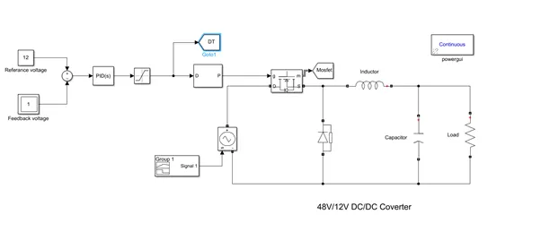
For the above question, I made the following circuit.
Requirement
Output voltage = 30 V, Input Voltage = 40-50 V
Power = 500 W
Current: - 12.5A
Voltage Ripple: - 10%
Current Ripple: - 5%
For this converter, we will use MOSFET as a switching device.
Duty Cycle: - Vout /Vin = 30/40 = 0.75
As in general converter, we will design a device with 100 K Frequency.
Design of Load:- for Load to be 12.5A= 30/12.5= 2.4 Ω
Design of Inductor, with 10 % ripple in current. As to limit ripple below 10% we will consider 5% ripple while designing Inductor.
L=`(Vout*(1-D))/(f*∆I)`
By solving this equation: - `(30*0.75)/(100000*0.05)`= 0.15 mH
Design of Inductor: - To limit voltage ripple below 5%, we will consider ripple only at 2.5 %.
C=`(1-D)/(8*L*f^2*(∆Vout/Vout))`
By solving this equation we get
C=`0.75/(8*0.00012*100000*100000*0.025)`= 8.33 micro F
By using all these values we construct the below diagram of the converter in Simulink.
Closed-loop feedback circuit:-
The main objective of this assignment is to make the feedback circuit for this buck converter due to which, either if there is voltage fluctuation in input side, output voltage will not fluctuate.
For this there are two ways, we can use PID controller for which we have to find optimum values of gains OR we can compensate the duty cycle by which output voltage is differing from input voltage.
In this assignment, I used 1st method:-
For the general case when voltage is not fluctuate
ing, we have a constant duty ratio 30 V. but if input voltage change to the feedback circuit will give compensation duty cycle to the circuit by which it will maintain the same output voltage.
In this assignment, we use a PID controller which will automatically adjust its gain to avoid fluctuation in output voltage.
In this circuit we use the saturation block after PID gain, to limit the duty cycle to 1 only. Because in practical life duty cycle can never be more 1.
Result:-
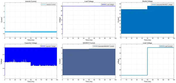
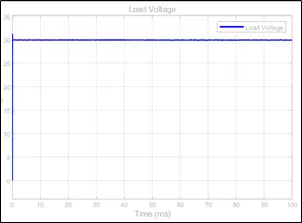
This is the output scope for the CCM buck converter, as discussed earlier we are using a PID controller to track the changes in output and keep it at 30 V constant.
For the calculation of inductor and capacitor, we are considering the worst-case condition. Hence any case our output ripple in current and voltage will be the desire limit.
At time 0.05 s, the output voltage is changed from 40V to 45 V, still, output voltage is maintained at 30 V
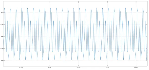
Output Inductor Current:-
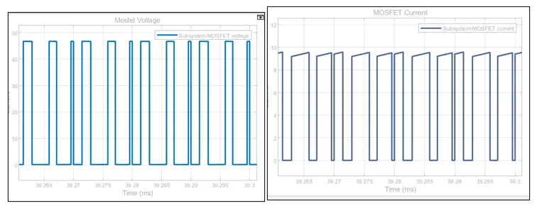
Mosfet Voltage & Current:-
Transient and steady-state voltage:-