Meshing of a Rear-view Mirror with 3D Elements using ANSA
INTRODUCTION
There are numerous patents filed regarding the rear-view mirror. They are concerning the attachment of sensor, anti-glare mirror, use of liquid crystal mirror, attachment of control circuit to measure the intensity of lights of the rear vehicle for taking corrective action against it, etc. Filing such patents and running investigations for the development of any product or assembly can stop after some time. However, the thing that cannot be stopped is the testing of any product for its use for different purposes. Investing a large amount of money for experimental testing of some simple parts is sometimes a cumbersome process for any industry.
Finite element analysis is one such method where a product can be tested multiple times and in various kinds of environments. In this work, the rear view of the vehicle is taken as a product to discretize it with solid elements. The very basic purpose of a rear-view mirror is to show the rearward view to the driver. In cars, it is fixed at the top of the windshield.
While testing a complete car model with FEA, its inner components cannot be missed out, as they could also be harmful in any accidents. Negligence for any small components could bring uncertain harmful moments and therefore, discretization of even smaller components like rear-view mirror is also required.
The rear-view mirror plays a vital role in a car enabling driver comfort in viewing the rear side. It has given ball and socket joint with which it can be adjusted to any angle. The driver can therefore adjust it to his own comfort.
- Aim
To prepare each component of the rear-view mirror for the finite element analysis, using solid elements.
- Objective
To discretize a rear-view mirror model into a finite number of solid elements for finite element analysis using pre-processor software viz. ANSA.
PROCEDURE
An IGS file of the rear-view mirror model was imported in ANSA. It was quite distorted and unarranged as shown in fig. 1. There were 4 separate PIDs for glass and its back support, a ball of the ball-and-socket joint, and stand. In this model, it is required to do solid mesh, therefore mid-surface extraction is not required here. After geometry cleanup, meshing had to be started directly – first shell mesh and then converting it to solid.
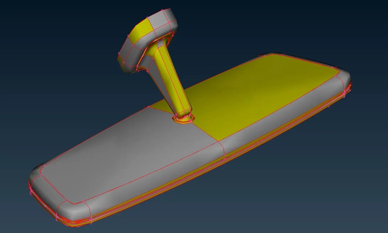
Figure 1: A rear-view mirror model after importing into ANSA, in distorted and unarranged condition.
- Geometry Clean-up
After using topo and joining adjacent surfaces, the model did not have many errors apart from the one that the adjacent parts got joined. This resulted in the generation of a triple con. In assembly, each part should be geometrically perfect viz. it should not have any errors individually. Associativity of any part with another is not a part of preprocessing.
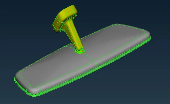
Figure 2: Error-free model of rear-view mirror with 1 mm distance between each node.
As shown in fig. 2, the model was cleaned from errors, and nodes were maintained to 1 mm distance to check if any distortions are present on any surface.
- Setting Quality Criteria
An industry sets the quality parameters required for the analysis purpose and provides it to the CAE team, depending on which geometry has to mesh. In solid mesh modeling three parameters are generally provided viz. minimum and maximum lengths, and tetra collapse. The criteria provided for this model is as shown in table 1:
Table 1: Quality criteria for elements.
| Target/Average length | 1 mm |
| Minimum length | 0.5 mm |
| Maximum length | 2 mm |
| Tetra Collapse | 0.2 |
- Shell Mesh Generation
After freeing the model from every sort of error, it is ready for the shell-mesh generation. In solid mesh modeling, mid-surface extraction is not required. Shell mesh has to be performed directly on the surface.
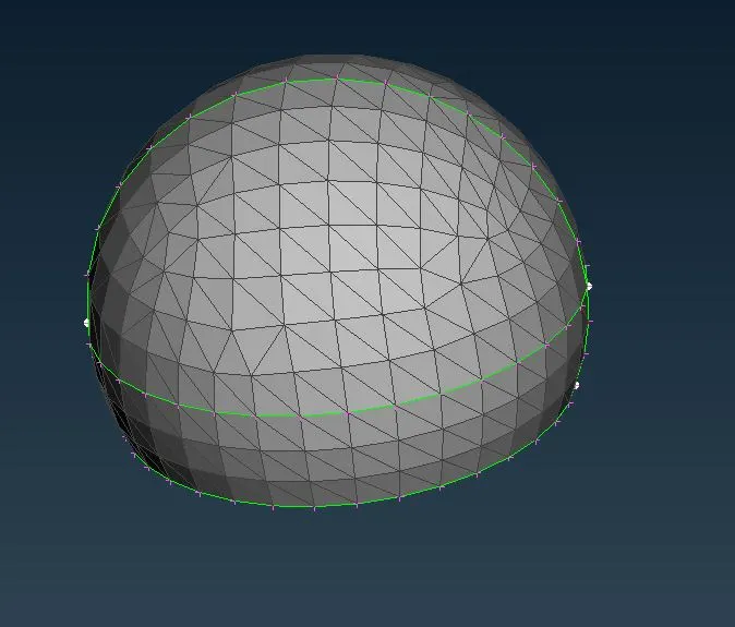
Figure 3: Shell meshing of the ball of ball-and-socket joint with ortho-tria elements.
In solid mesh, two kinds of elements are existing viz. tetra and hex elements which are the 3-d form of tria and quad elements. Tetra is a 4-noded element and hex is an 8-noded element in the first order. So, for generating 3-d elements, 2-d or shell elements are used.
For meshing with tria elements, ortho-tria or tria elements are used. Ortho tria is used where curves are present. It is because it has good surface capturing quality. But because the computational time for ortho-tria is higher than normal tria, where ever possible like on flat surface tria elements are used.
- Shell-to-Solid
In solid mesh, there are two kinds of mesh elements viz. tetra and hexa. Hex or structured elements are an ideal element. However, because it takes a larger amount of time for computation, it is only used where there is a critical part to be analyzed. Else, tetra elements are used.
Tet elements are the volume given to the trias and are used where the thickness is much greater. For meshing with solid elements, the volume has to be defined, and then it has meshed with tet rapid or tet FEM algorithms. Tet rapid and tet FEM are the type of tetra elements algorithms. In Tet rapid algorithm elements has an unorganized rate of growth of elements, however, in tet FEM algorithm it has some consistency of rate of growth of elements up to certain layers. Figure 4 shows the solid mesh modeling of the ball of the ball-and-socket joint.
In figure 4, it can be seen that after converting shell to solid, the CAD geometry is associated with the elements. Therefore, after meshing with solid elements, the shell has to be released and has to make unassociated with each other. Figure 5 shows the elements and the CAD parts with no relation to each other. This is how all the parts are meshed and made unconnected with their geometries. Solid elements are kept under different PIDs, unconnected with their geometries.
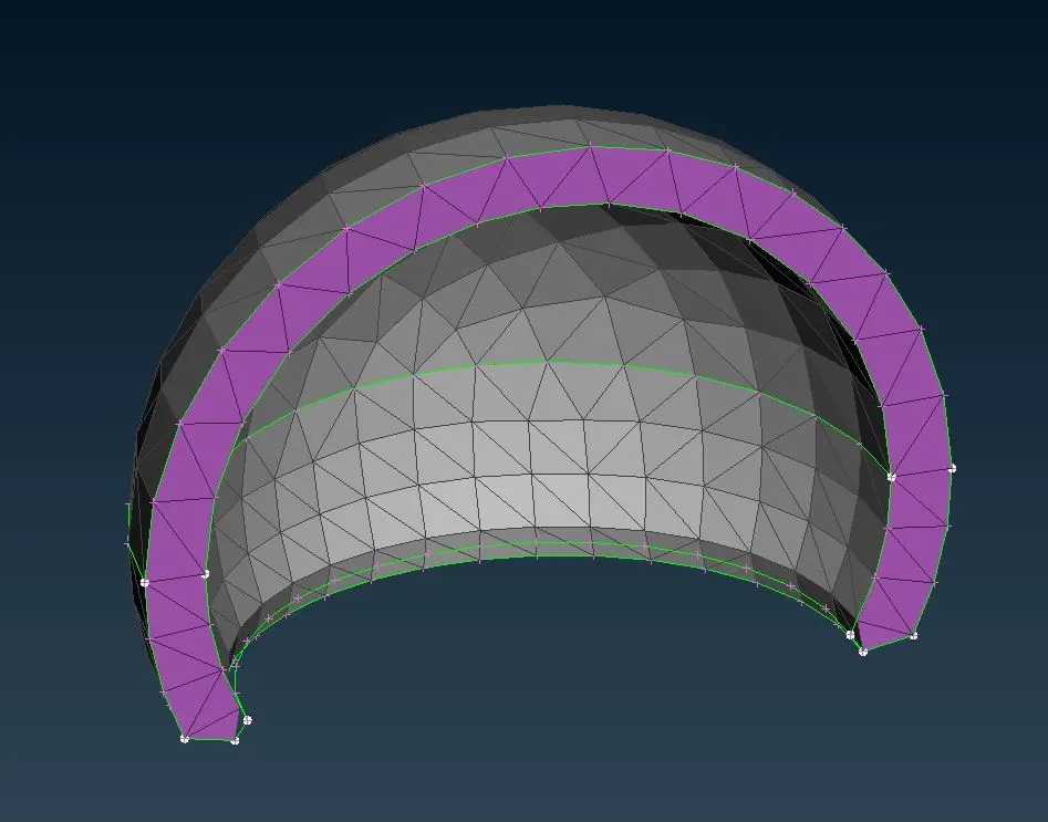
Figure 4: Meshing of a ball of ball-and-socket joint with solid(tetra) elements.
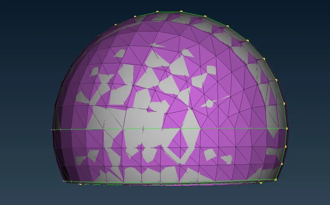
Figure 5: Ball of ball-and-socket joint, unconnected with CAD geometry.
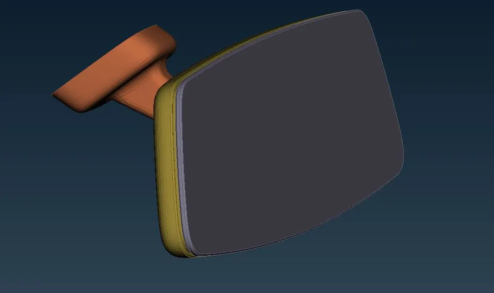
Figure 6: Complete solid meshed model of a rear-view mirror (released from CAD geometry)
CONCLUSION
Parts or assemblies where the thickness is not regular or if it is above 5-6 mm. It generally meshes with solid elements. In solid meshing, if a part is not so much important to give attention, whose presence is required, or which is stiffer, it has meshed with tetra elements. If it is a critical part or a portion of any part, it has to have meshed with hex elements.