Deploying 1d Connectors in Rear Side Door of a Car using ANSA
- INTRODUCTION
A rear door of a car is subjected to a high vibration environment while a car is running. So, to analyze any part of the car a good deployment of the connection is required before any simulation. Any missing connection would lead to inaccurate results of the simulation. Door stiffness is directly related to the noise generated in the car. It was found that adding new components or sealing would increase the cost, therefore, providing enough stiffness to the door was the only smarter way to decrease noise level at the early stages of the new vehicle development.[2] Bolted joint, spot weld, and seam weld are some of the connections used in the rear side door of a car. Apart from these three connections, special attention has to be given to the rubber strips, provided at the border of the glass. Technically, it is called a weatherstrip. As the name indicates, it is a sealing to safeguard the car’s internal atmosphere viz. air conditioning, wind noise, etc. Sealing on doors or any other part of the car’s body are provided to avoid noise from wind or road, and facilitate as a damper to minimize vibration.
Side doors are attached to the frame of a car. Therefore, the vibration, arriving from the powertrain, also gets distributed in the door part through hinges. Vibration in the body of the car shakes the system generating sharp knocking sounds, a noise called rattle, which is evaluated through sensors and accelerometers, or subjectively by NVH engineers.[1] Therefore, rigid support has to be given to the hinge part, provided it shouldn’t be completely constrained. It is because a door will always have at least one dof free (one rotational dof for opening and closing of door).
The connections for mechanisms provided to uplift and down lift of the glass, the latch for locking a door, are to be given accordingly. In FE software, names for each kind of connection (like bolt or weld) are named by the way the element acts. For example, two elements viz. RBE2 and RBE3 serve to rigidize the elements, generally used where bolt connections are there. But here, the major difference between those two elements is, in the RBE2 element there is one master node (or independent node) and multiple slave node (dependent nodes) and vice-versa. In this work, various connections used in the door of a car are studied, and accordingly, FE connections are deployed.
Aim
To deploy connections in the FE model of a rear door of a car, using elements to represent bolt joint, weld joint, and dampers and mass.
Objective
- To study the kind of connections used in the door of a car.
- To deploy those connections in a FE model of a door using NASTRAN deck elements.
- PROCEDURE
The FE model of the rear door, that was available to work for deploying connections, was in .nas format. After importing the file into ANSA, it was found that every part is kept in a single PID, as shown in fig. 1. For deploying connections, it was required to have separate PIDs for each different part of the door. Therefore, before working with connections, each part was segregated and kept in different PIDs, as shown in fig. 2(a) and fig. 2(b). It facilitates the ease of deploying connections between different neighboring parts.
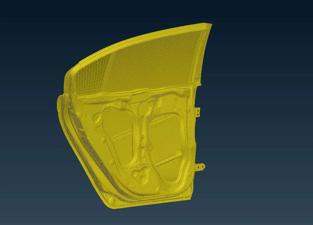
Figure 1: FE model of the rear door of a car, having each of its parts kept in single PID.
From fig. 2(a) and fig. 2(b), it can be seen that the inner and outer body of a door is kept in separate PIDs. It is because the inner panel has a little more thickness in its some region, that is decided after optimization. But because it couldn’t be guessed its area in the inner panel, supposing its uniform thickness, the inner panel is kept in separate PID.
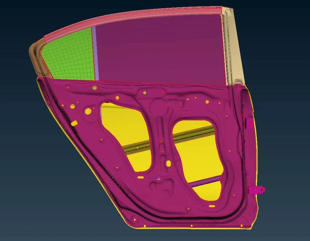
Figure 2(a): Inner side of a rear door, having each of its parts kept in different PIDs.
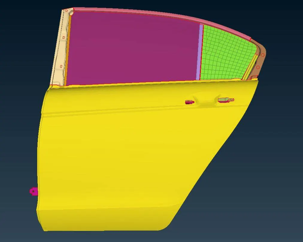
Figure 2(b): Outer side of a rear door, having each of its parts kept in different PIDs.
RBE2 and RBE3 Elements
The testing of fasteners for the vibration is a key to deliver safe engineering, by ensuring that all the fasteners are fit for the purpose, for which they are designed, and will not fail in the service period. Vibration is desirable for some applications but more often it is undesirable. Vibration wastes energy and creates unwanted noise and wear that leads to the development of stress in the mechanical system. This causes fatigue and/or a decrease in service life.[3] Bolted connections are widely used in assemblies due to the advantages of their ability to effectively clamp the parts and easy removal of the clamped parts for maintenance and repair.
However, when dealing with any mechanical system, unless the focus of the study is purely on joints or connections, bolted connections are supposed to be a rigid connection. There are two types of elements used to represent bolted connection viz. RBE2 and RBE3 elements.
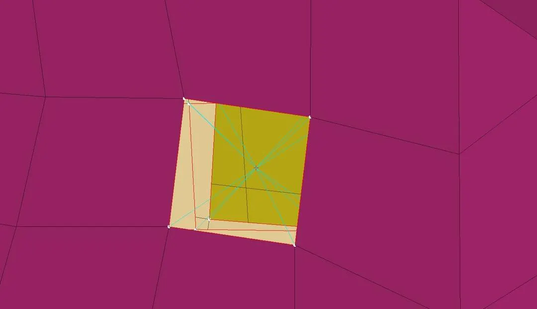
Figure 3: RBE2 spider connection.
As shown in fig. 3, it is an RBE2 element (without stem or spider connection). The property of connection with the RBE2 element is that there is a single master node (or independent node) and multiple slave nodes (or dependent nodes). Another difference between them is that RBE2 provides tremendous stiffness however RBE3 element does not provide the stiffness but distributes it to the neighboring nodes. Therefore, when infinite rigidity is required RBE2 element is used and when little deformation is also needed to be seen RBE3 element is used. Connection with RBE2 and RBE3 also has sub-types – spider connection and connection with a stem. In fig. 3, it can be seen that each node on the perimeter is connected to a single node present at the center or master node. It is called a spider connection. The length of a bolt is shown as a stem in FE connections. In fig. 4, each node on the perimeter is connected to a center node lying in the plane of the surface and each center node is connected, represented by a yellow line, called a stem. It is called a connection with a stem.
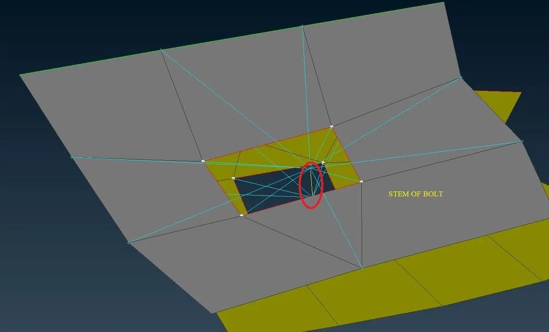
Figure 4: Yellow line representing the stem of a bolt.
Connections can be deployed automatically or manually. In the automatic method, a 3-d point has to be created at the center of the perimeter or the COG of the perimeter for any single surface, among all the surfaces which are to be connected using a bolted connection and then convert into a connection entity called a bolt, as shown in fig. 5(a) and 5(b).
Using the connection manager, that created 3-d point has to be selected and after hitting enter, a window of connection manager gets opened. Because the connection entity was a bolt, therefore, the window of the connection manager would have all its properties related to bolt only. Fig.6 shows the window of the connection manager.
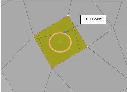
Figure 5(a): 3-d point generated at the COG of the square hole perimeter.
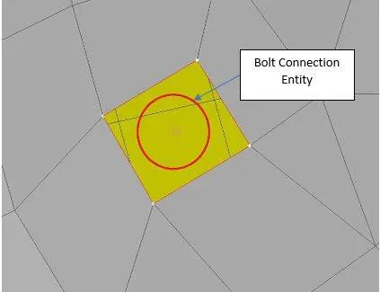
Figure 5(b): 3-d point converted into bolt connection entity.
In connection manager, P1, P2, P3, and P4 are the surfaces that are to be connected. For bolt connection when the ‘Bolt’ option is selected in the ‘FE Rep Type’ section, properties of bolt opens as shown in fig. 7. In those properties, ‘Search distance’ is the minimum distance of dependent nodes from the connection entity. A value of 20 is given in the work as a search distance.
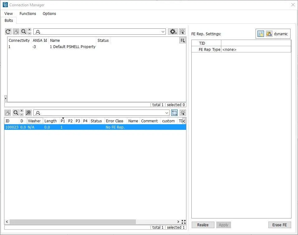
Figure 6: Connection manager window.
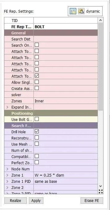
Figure 7: Properties of a bolt when ‘bolt’ is selected as a ‘FE Rep Type’.
Kind of nodes selection viz. only inner nodes or only outer nodes (nodes of washer elements) or both (each node or four opposite neighboring nodes making ‘X’), for such selection ‘Zones’ option is helpful. ‘Head Type’ is set as RBE2 but ‘Head Dof’ is not the same for all rigid connections. For most of the connections, it is ‘123456’ i.e. they are completely constrained, however, for hinges it is ‘12345’. 6 is not there because the door has to rotate freely in one direction, for opening and closing, therefore one rotational freedom is given in z-direction.
If a stem of the bolt is required then the ‘Body’ option in the ‘Body’ section has to be checked and if not required it has to be unchecked.
RBE3-HEXA-RBE3 Element
Along with bolted connections, spot welds are also used extensively in automobile parts. In CAE, there are some options available to select an element type, for a single kind of connection. For example, there was two option for use to represent the bolted connection. Similarly, the weld connection also has 3 options – RBE, CWELD, and RBE3-HEXA-RBE3.[4]
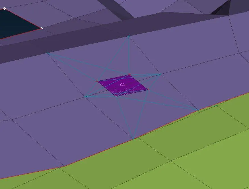
Figure 8: RBE3-HEXA-RBE3 connection, connecting surfaces of two separate PIDs.
In this work, the RBE3-HEXA-RBE3 element is used because it is a good option for a weld connection in NVH. It is a solid hexahedral element with two RBE3 elements. As discussed earlier, RBE3 has multiple independent nodes, in RBE3-HEXA-RBE3 connection, a node of Hexa element is connected to each node of a single shell element, as shown in fig. 8.
To create this connection, a 3-d point has to be created at any shell element of anyone's surface, and then it has to be converted to the ‘spotweld’ connection entity, as shown in fig. 9. Using the connection manager, that created 3-d point has to be selected and after hitting enter, a window of connection manager gets opened. Because the connection entity was a spotweld, therefore, the window of the connection manager would have all its properties related to spotweld only.
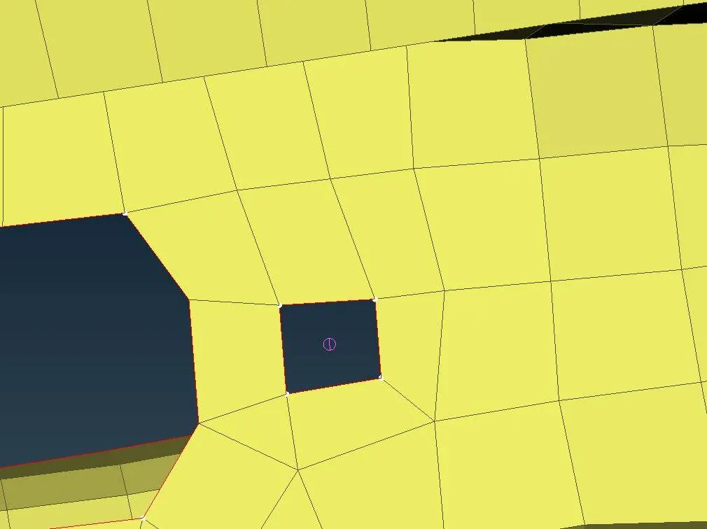
Figure 9: 3-d point converted to ‘spotweld’ connection entity.
In connection manager, P1 and P2 have to be selected as the surfaces which are to be welded. RBE3-HEXA-RBE3 to be selected as ‘FE Rep Type’. In the ‘Interface’ section, by default only translational movement is coupled, therefore, rotational movement is also needed to coupled. For that, ‘RBE3 Pinflags’ has to be set as ‘123456’ instead of ‘123’. Separate PID has to be created for a weld connection and has to specify it in PSOLID ID in the ‘Body’ section. A search distance of 20 was specified for the given work. After applying the set properties and values, the spotweld connection can be seen as shown in fig. 8.
RBE3-CBUSH-RBE3 Element
Weatherstrips plays a vital role in isolating passenger compartment from the external environment. A higher seal load is good for NVH, it adds more damping but parallelly it also affects the door closing effort. [1] In FE, weatherstrips are represented as dampers or CBUSH elements. In this work, RBE3-CBUSH-RBE3 elements are used to represent damping elements. In RBE3-CBUSH-RBE3. There are two RBE3 elements and one CBUSH element. The role of the RBE3 element here is not to provide stiffness but distribute the load in dampers.
In the rear door model of the car, CBUSH elements are used at the border of the glass. For that to happen, at first, the curve of the glass has to be taken out to carry out the process of placing CBUSH elements, by using the ‘Feat2Curve’ option in MESH>Perimeters. ‘Feat2Curve’ creates the 3-d curve from the mesh feature line. Fig. 10 shows the curve created for the glass shape. It has to be then converted to ‘Spot Line’ as ‘Connection Type’. After converting it looks bold than earlier and purple, as shown in fig. 11.
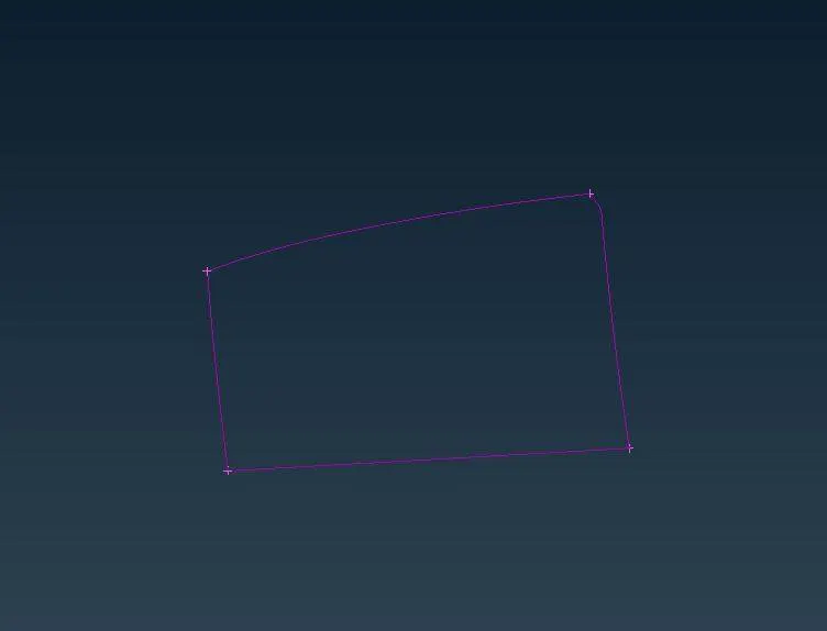
Figure 10: Curve of the glass shape, taken out by using the ‘Feat2Curve’ option.
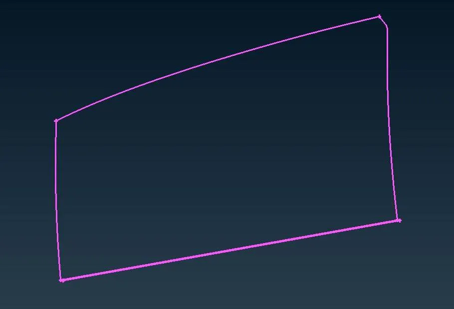
Figure 11: ‘Connection Type’ of the curve has been converted to ‘Spot Line’.
One important point here is that glass would have damping on both of its faces. It means that it should have damping elements on both sides. Therefore, a curve close to the parent curve is also created on one side, as shown in fig. 12.
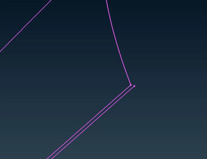
Figure 12: Another curve close to the parent curve for representing damping elements from both sides.
Now, the same as before, using the connection manager curve has to be selected and when hitting enter, it would open the window for properties related to the damping system. In that window, P1 has to be selected as the glass part and P2 has to be selected as the neighboring parts on which the other end of dampers would lie. ‘RBE3-CBUSH-RBE3’ has to be selected as the ‘FE Rep Type’. When the properties of RBE3-CBUSH-RBE3 gets opened, the search distance has to bit more. In this work, 50 is given as the search distance value. ‘Keep All Branches’ has to be turned on so that all the identified elements would be maintained in RBE3. Separate PID has to be assigned to the CBUSH elements. While the PID is being set, it will open the window to set the value of KI, K2, K3, K4, K5, and K6, as shown in fig. 13. They are nothing but stiffness in different directions. Their values are pre-determined and the values are 0.001, 0.001, 0.001, 10, 10 and 10 respectively.
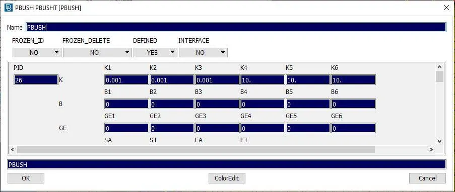
Figure 13: Window to set the values of stiffness in different directions.
One more important thing here is that the distance between two CBUSH elements has to be given and it should be less than half of the length of the curve. After applying all the properties CBUSH elements connected to glass and its neighboring supporting parts can be seen as shown in fig. 14(a) and fig. 14(b).
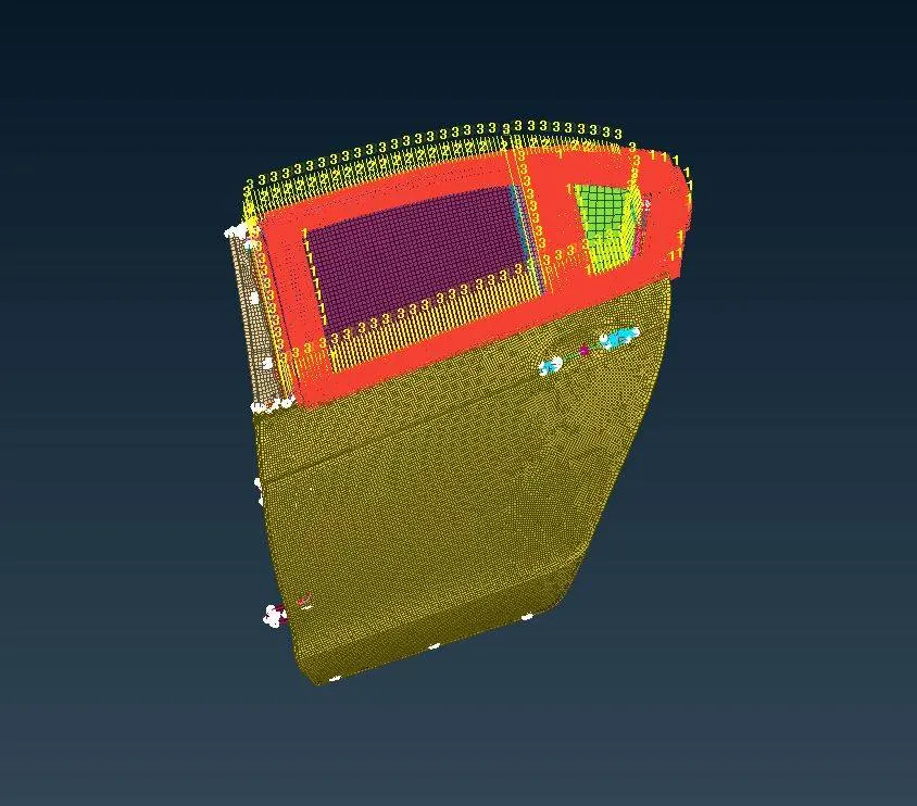
Figure 14(a): RBE3-CBUSH-RBE3 connection deployed on the border of the glass.
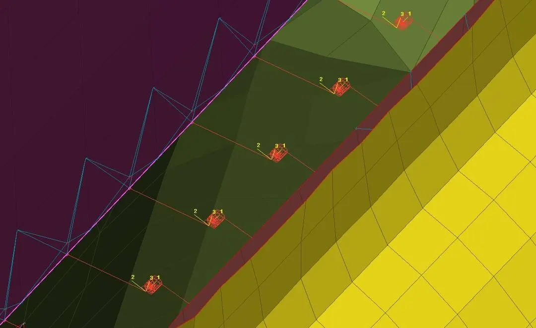
Figure 14(b): Bush elements.
After the bush elements have been deployed, it can be observed that they are not aligned with the global co-ordinate. As per the modeling guidelines, the local coordinate of these bush elements has to be oriented with the global coordinate. Therefore, in Database>CONNECTION>SpotweldLine_Type, in properties of a bush connection, orient has to be changed to ‘with coordinate’ from ‘with vector’, with its value 0. The value ‘0’ means it is a global coordinate. Fig. 15 shows the window of bush element properties.
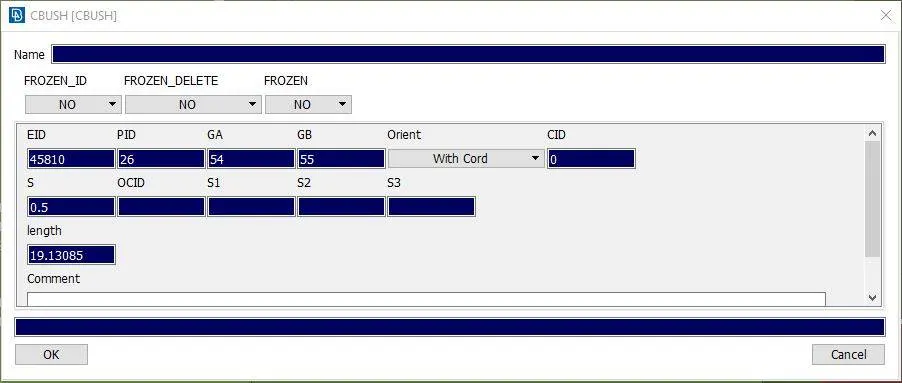
Figure 15: CBUSH element property window.
CONMi Element
CONMi element is used to represent the concentrated mass. In the given rear door FE model, the handle of the door was not present. Therefore similar element had to place their which would represent the mass of the handle. For that to develop, two holes of the handle were rigidized manually using the RBE2 element. Then using CONMi>CONM2>Nodes, two master nodes were connected. This developed the center node to which mass could be assigned. Using the ‘INFO’ option in the NASTRAN deck, in the ‘ELEMENTs’ section on that central node, a window opens as shown in fig. 16. In the figure, the M is the mass that has to be assigned. The mass should be in tonnes. Therefore, considering the mass of the handle to be grams, the value of M was assigned a value of 0.0001.
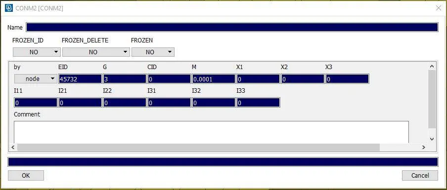
Figure 16: Property of concentrated mass.
All the basic joints that are used in a car’s door have been deployed in the FE model of the door. An effort has been taken to check each location where a connection should be deployed. Fig. 17(a) and 17(b) shows the complete FE model of the door with all of its possible connection deployed.
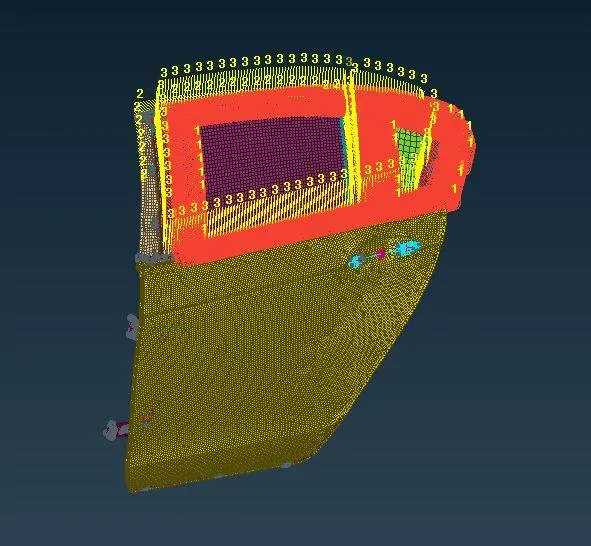
Figure 17(a): Outside view of the FE model of rear door with all its connections deployed.
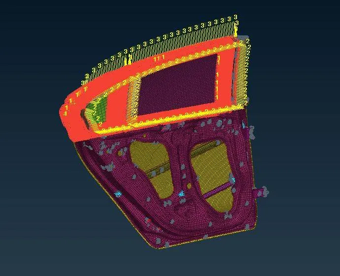
Figure 17(b): Inside view of the FE model of the rear door with all its connections deployed.
- LEARNING OUTCOME
In this work, the kind of connections used in the door of a car has been studied and its representation in FE has been understood. The use of four kinds of elements has been studied namely RBE, RBE3-HEXA-RBE3, CBUSH, and CONMi for bolt joint, weld joint, dampers and to represent concentrated mass respectively. The following are some of the learning out of this work.
- RBE2 or RBE3 element is used to represent the bolted connection.
- RBE2 has infinite stiffness, however, the RBE3 element is an interpolation element which generates multi-point constraint equations in simulation and thereby distributed the load.
- RBE element modifies the local mesh pattern.
- RBE3-HEXA-RBE3 is generally preferred in FE for weld connection, especially when the work is for the NVH simulation.
- Dampers can be represented by CBUSH elements.
- According to new guidelines, the local coordinate of bush elements should be aligned with the global coordinate.
- If some mass is absent, for example, the handle was missing in this work, it can be represented by using the CONMi element. CONMi represents a concentrated mass.
- CONCLUSION
CAE or computer-aided engineering on any model requires good observation and knowledge about the kind of manufacturing used, the way various parts are joined, the working environment of that particular system, and more especially its use. In this work, the kind of connections used in the door of the car has been studied and the way it should be represented in FE has also been studied. There are several options available for the element to choose to represent any specific kind of connection. Some of those elements are studied in this work, for example, RBE, RBE3-HEXA-RBE3, CBUSH, and CONMi, and many more are there to study.
References
[1] Filho, R., Fromel, I., and Osti, R., Closures Weatherstrips with Variable Cross-Sections, SAE Technical Paper, 2018, 2018-36-0152.
[2] Talay, E., Altinisik, A., The Effect of Door Structural Stiffness and Flexural Components to the Interior Wind Noise at Elevated Vehicle Speeds, Applied Acoustics, 2019, Volume 148, Pages 86-96.
[3] Ksentini O., Combes B., Abbes MS, et al. Numerical Study Of Self-Loosening of a Bolted Assembly Under Transversal Load, Mech Ind, 2016, 17(5).
[4] Jahani, K., Beigmoradi, S., and Bayani Khaknejad, M., Investigation of the Effect of Different Spot-Weld Modeling Approaches on Fundamental NVH Virtual Simulations, SAE Technical Paper, 2014, 2014-01-0025.