Comparison of Different Meshing Techniques
- INTRODUCTION
CAE or computer-aided engineering is the process of making a product from its design, considering the kind of manufacturing process it should undergo, the material selection, its’s shape, and mass optimization, etc. to its computerized testing using various mathematics- and physics-based algorithms. FEM can be called a part of CAE. In FEM or finite element method, it is all about discretizing any part into small-sized elements. Physics is then applied to those elements and then results are combined and seen as the resultant for the original part. This is the basis of any finite element analysis technique. Physics viz. direction of force, the magnitude of a force, dofs at any surface or moment on a beam, etc. have to be applied by studying the application and, they are specific and limited in its nature. But the important thing before applying physics needs the ground to which physics has to be applied, in FEM. Meshing is one of the most important parts of any simulation. In meshing, a part is discretized into many 1-d, 2-d, or 3-d elements.
While meshing with 2-d elements or shell elements, a flow of elements has to be maintained. It is because, as smooth the flow of element as smooth the flow of energy, within the body of part, would be. There are also a few more things that have to kept in mind while meshing any part.
Tria is the stiffer element among shell elements. Therefore, it is tried to kept minimum trias when deformation or deflection is one of the focuses of study. In sheet metal parts, trias are generally kept minimum. Along with these conditions, trias are also not kept facing opposite to each other because convergence error could occur. It is also tried to not let the trias fall on the perimeter. It is because it does not let the good results to occur on the perimeter side.
Ultimately, while meshing, it has to keep in mind that a flow of elements has to be maintained with minimum trias. In ANSA, meshing can be worked on in three ways –batch meshing, casting meshing, or manual meshing. In this work, meshing has been done on a random component, having many complex geometrical features in it, using those three meshing techniques and was tried to find the best suitable technique for meshing amongst them.
Aim
To compare the quality of mesh pattern amongst batch meshing, casting meshing, and manual meshing and find the best meshing technique.
Objective
- To study different kinds of meshing techniques viz. automatic and manual method.
- To find the best technique which gives good looking mesh flow pattern.
- PROCEDURE
To study the different techniques of meshing, a random component had been taken as shown in fig.1. It can be observed from the figure that the geometry was very much disturbed. Therefore, before initiating any meshing technique, it was required to clean the geometry and make it look good and out of any kind of defects.
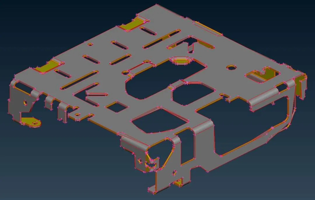
Figure 1: Random component to study different meshing techniques, having many geometrical features.
To rectify the errors, a command was given to join all the neighboring cons, using the ‘Faces>Topo’ tool, in the TOPO deck. Geometry was also smoothened by adjusting the distance between each node to 1mm, to observe the geometrical features.
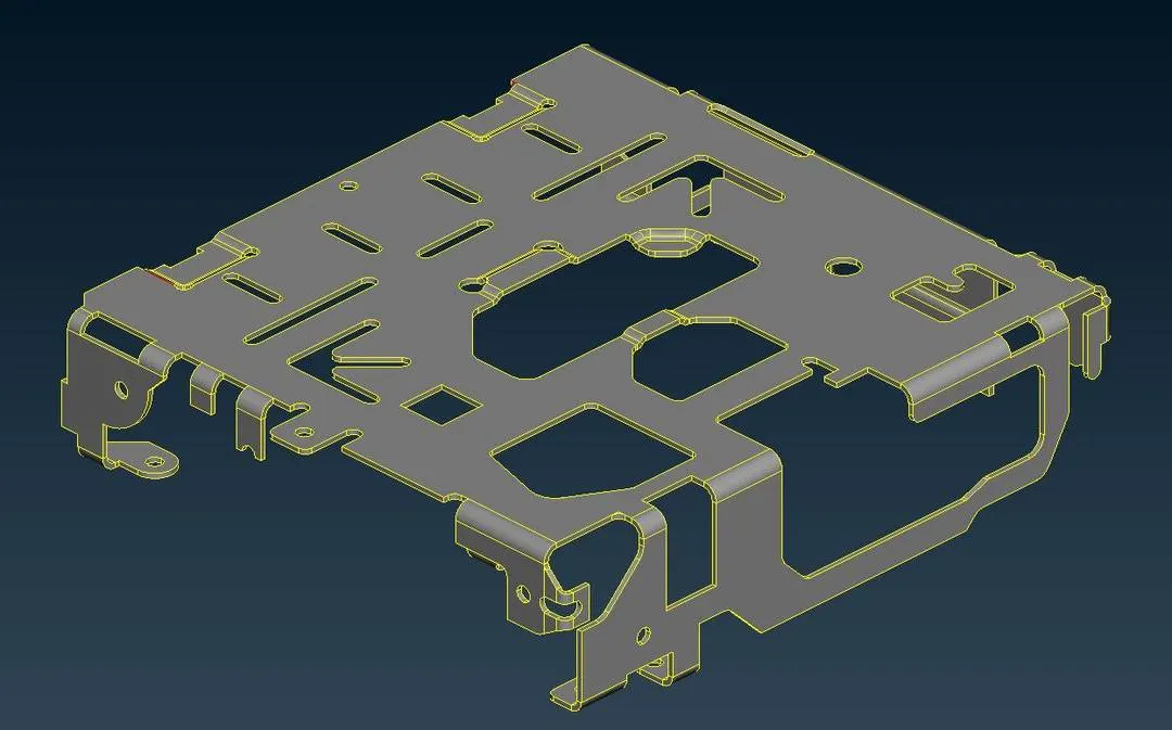
Figure 2: Geometry with some of its errors rectified.
Even though many of the geometrical errors were rectified using the ‘Topo’ tool, it was still having 25 different kinds of errors present in it, as can be seen from fig. 3. The geometric check manager had shown the presence of errors related to single cons, triple cons, needle faces, and cracks between faces. All the errors are then rectified using both manual and automatic methods.
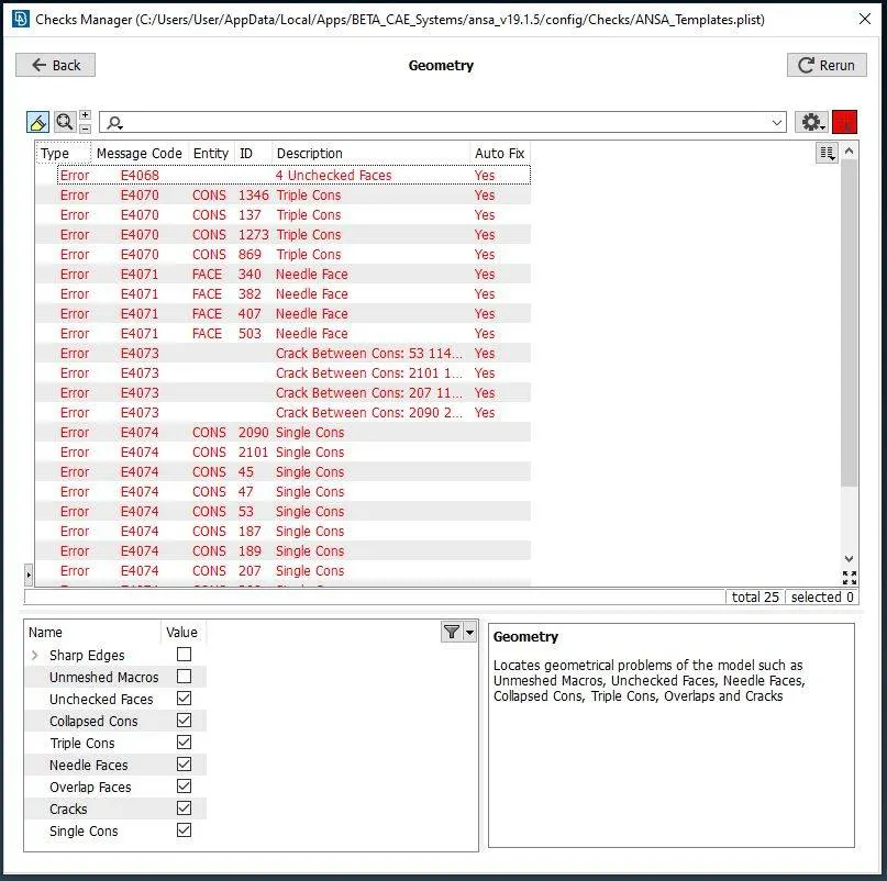
Figure 3: Geometrical check manager window showing the presence of different kinds of errors in the geometry.
Now, when the geometry was free from all the errors, next important thing was to set the quality parameters. The quality parameter for the element is as shown in table 1. After the quality had been set for the elements, the geometry was then ready for the meshing. Out of automatic methods of meshing and manual method of meshing, the automatic method was taken first to mesh the component. It is because it takes less time to mesh the component. Batch mesh and casting are automatic methods. The one difference between batch mesh and meshing using the ‘casting’ tool is that in batch mesh, the mid-surface has to be extracted at-first and then it has to mesh while meshing with the ‘casting’ tool, it extracts the mid-surface and also mesh it and directly gives the FE model.
Table 1: Quality parameters for the element.
| Target/Average length | 3 |
| Minimum length | 1 |
| Maximum length | 5 |
| Aspect | 3 |
| Warpage | 15 |
| Skewness | 45 |
| Jacobian | 0.7 |
| Minimum Quad Angle | 45 |
| Maximum Quad Angle | 135 |
| Minimum Tria Angle | 30 |
| Maximum Tria Angle | 120 |
| Tria Percentage | 15 |
Batch Meshing
In the batch mesh procedure, firstly, a mid-surface had to be extracted. To extract mid surface with an automatic process in the ‘TOPO’ deck the ‘Faces>Mid-Surface>Skin’ tool is used. Using this tool when geometry was selected, it identified the two faces of the component and the face at its thickness side. It was represented as green, red, and blue in color, as shown in fig. 4(a). Blue color represents the thickness, as shown in fig. 4(b).
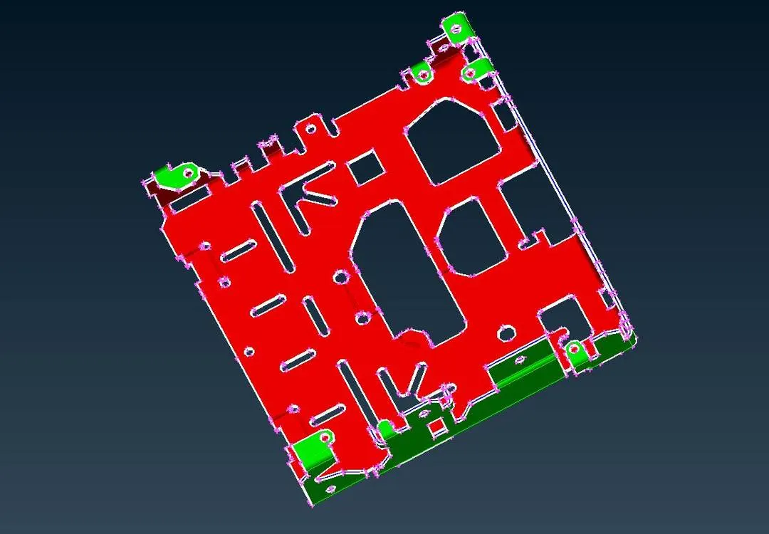
Figure 4(a): Automatic identification of two faces and face at the thickness side, using the ‘Skin’ tool.
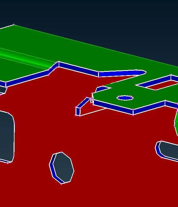
Figure 4(b): Blue color representing thickness side of the component.
When using this ‘Skin’ tool, red and green faces should never be adjacent. It comes as an error when this tool is used. Red and green faces should always be separated by a blue face. Figure 5 shows the mid-surface extracted using the ‘Skin’ tool.
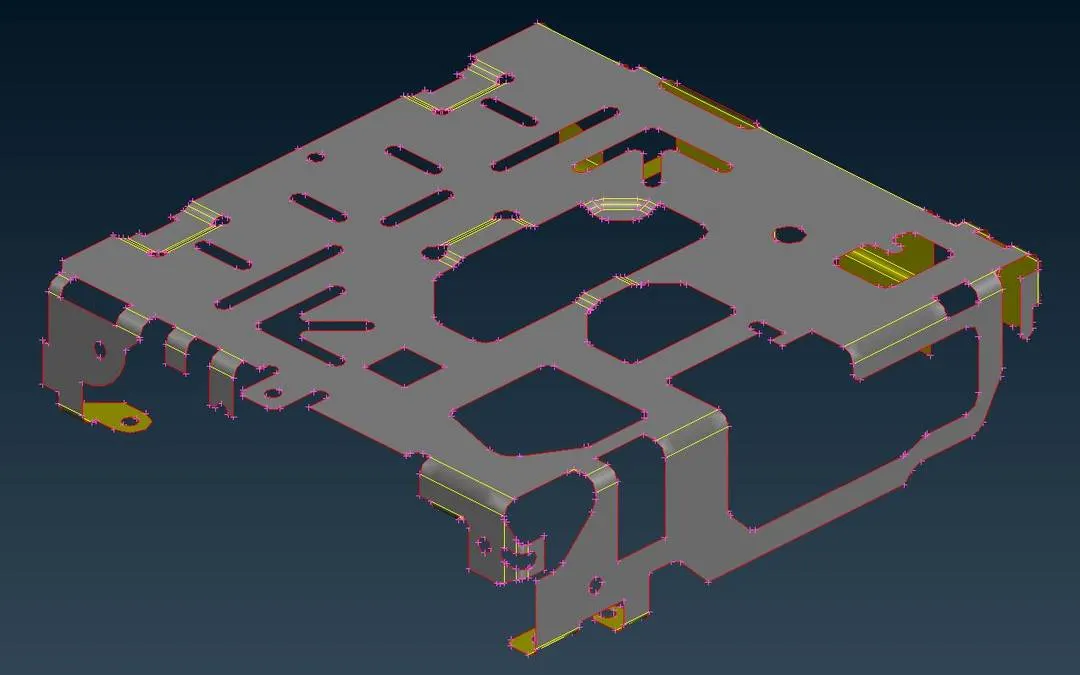
Figure 5: Mid-surface extracted using the ‘Skin’ tool.
From fig. 5, it can be observed that the ‘Skin” tool had given quite a good mid-surface. Therefore, it could be taken as a surface to mesh. A mid-surface, if it is not capturing the geometric features of the parent body in a good manner, it cannot be taken as a surface to mesh because it would represent the wrong representation of the parent body. One thing to note here is that when the mid-surface is extracted automatically using the ‘Skin’ tool, it would delete the parent body and only the mid-surface would remain.
Now, to mesh the mid-surface using batch meshing the ‘Batch Mesh Manager’ comes into the role. In the batch mesh manager, the ‘Mesh Scenario’ has to be selected as a tool, as shown in fig. 6.
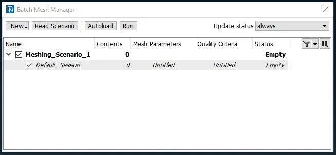
Figure 6: Batch mesh manager.
Before proceeding to batch mesh, quality parameters have to be preloaded. It can be check by double-clicking the ‘Untitled’ under ‘Quality Criteria’. Changes had to be made in the content of the ‘Meshing_Scenario_1’ and the PID of the mid-surface of the component to be selected as the part to mesh. When hitting ‘Run’, it took 2-3 minutes and gave a complete meshed surface as shown in figure 7. From fig. 7, it can be observed that the mesh flow pattern is good enough using the batch meshing method. It also had captured the features in quite a good manner. However, there were 166 trias and 1 off element were present. To get rid of trias and off element, the effort was taken to reconstruct the mesh and it was then appeared like as shown in figure 8. After reconstruction, off-element was not there and trias could be reduced to 126 only. Not much trias could be eliminated because it was leading to the generation of new off-element. Moreover, many trias were started falling on the edge of the perimeter. Many such trias were eliminated but many were remaining which couldn’t be eliminated, as can be observed in figure 8.
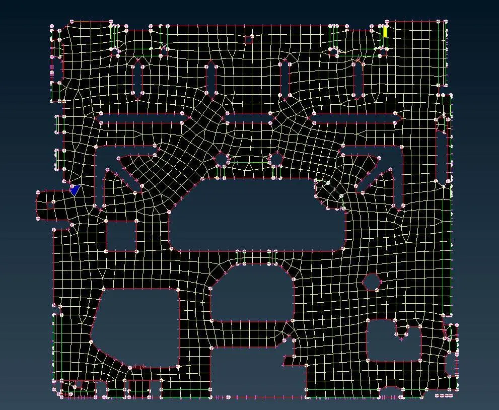
Figure 7: Meshing of the component using the batch mesh method.
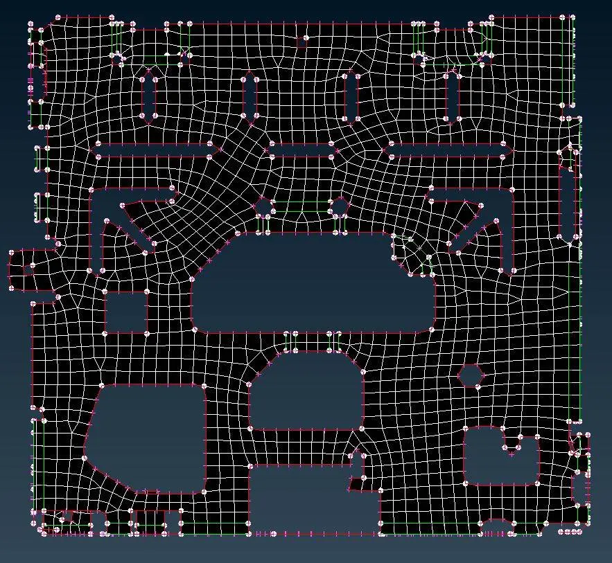
Figure 8: Reconstruction of the mesh, done using the batch mesh method.
Meshing Using Casting Method
When meshing with the casting method, it is a one-step automatic process. In this technique, in the TOPO deck, Faces>Mid-surface>Casting has to be selected. After selecting the casting tool, a window would appear as shown in fig. 9. In the figure, the minimum thickness had to be specified. Though the thickness was uniform all-over, 0.5 mm of minimum thickness was specified. The target element should be the length as specified in table 1.
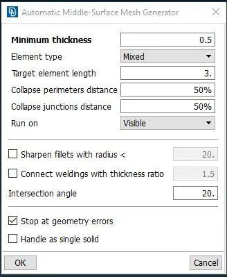
Figure 9: Window of automatic mid-surface and mesh generator, in meshing using the casting method.
When both the two parameters were specified and hit enter, it took 3-4 minutes and had given a ready meshed component, as shown in fig. 10. One thing to be noted here is, in the casting method, we do not need to extract the mid-surface and mesh it as we did in batch meshing. In the casting method, it extracts the mid-surface and also meshes it. And because it does two processes together, it takes a somewhat longer time compared to batch meshing. As can be observed from fig. 10, many off-elements were generated in FE using the casting method. There were 144 trias and 165 off-elements generated.
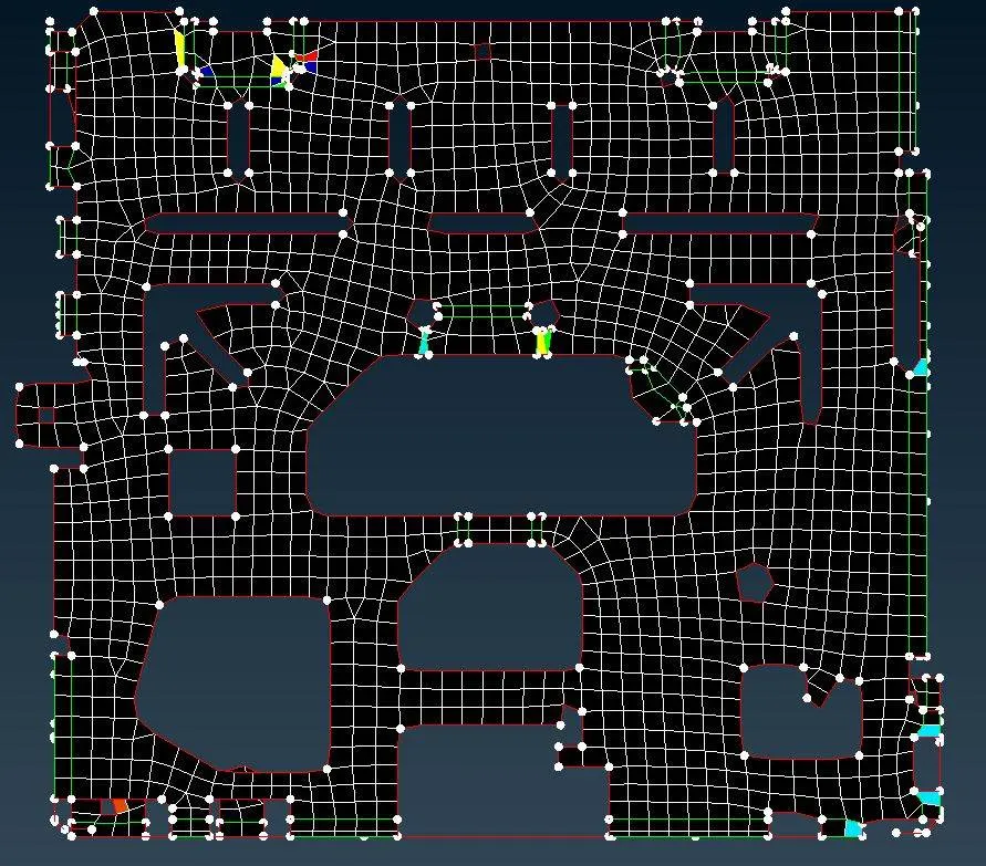
Figure 10: FE model of the component using the casting method.
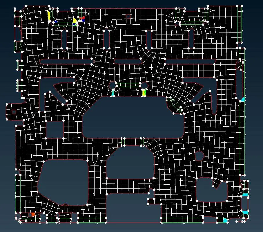
Figure 11: FE model of the component, using the casting method, after reconstruction.
After reconstruction, off-elements could be reduced to 30 and trias to 124. To reduce off-elements, reconstruction of elements was done but it was not found to very helpful. It is because, along with the poor flow of elements, this method also had not captured the features in a good manner. Fig. 11 shows the FE model of the component, using the casting method, after reconstruction.
Manual Meshing
The most important advantage of manually meshing the component is that a feature can be captured without disturbing any geometric shapes. In manually meshing the component, the mid-surface was extracted by offsetting the surface to the middle of the length of the thickness. Fig. 12 shows the mid-surface extracted out of the parent body of the component.
Figure 12: Mid-surface extracted, manually, out of the parent body of the component.
The mid-surface extracted was put under different PID and was assigned the thickness. One more advantage of using the manual method is that after extracting the mid-surface, the parent body does not delete if didn’t command so. Distance between nodes was adjusted to 3 mm, which is the target length of the element.
Before initiating meshing, the component was divided into small parts, so that the geometric shape of the component would not disturb. When the geometry was ready for the mesh, one-by-one the areas meshed manually. Each time when the area has meshed it was reconstructed, smoothened, tried to minimize tria elements and eliminate off-elements. And there-by indirectly much attention was given to even the small features of the geometry. Fig. 13 shows the manually meshed component. After completely meshing the component it was having 79 trias and 3 off-elements.
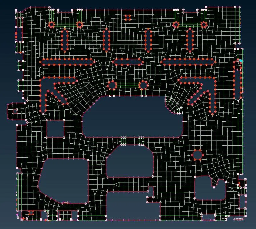
Figure 13: Manually meshed component.
From fig. 13, it can be observed that attention was given to the geometric shapes of the component. The orange spots were the hot-points that were marked as fixed so that they could not disturb while meshing and reconstructing the mesh. Attention was also given to maintain the flow of elements. However, some off-elements are still present in the component. It was because of the geometrical constraint. Because the less area was available, those 3 off-elements couldn’t be eliminated.
- RESULT AND DISCUSSION
The available component was meshed using three techniques. In batch meshing, the ‘Skin’ tool was used to extract the mid-surface and then meshed it using ‘Batch Mesh manager’. In the casting method, the ‘Mid-surface>Casting’ tool was used to mesh the component. It extracted the mid-surface and meshed the component in one action. In the manual method, mid-surface was extracted by offsetting the one surface of the component to its middle, and then it has meshed gradually. All three methods have an advantage and disadvantage of their own. Table 2 below shows a comparison between these 3 techniques.
Table 2: Comparison of three meshing techniques.
| Batch Mesh | Casting | Manual Mesh | |
| Parent Body Presence | No | No | Yes |
| Trias (before reconstruction) |
7.97 % or 166 Elements |
7.08 % or 144 Elements |
3.27 % or 79 Elements |
| Trias (after reconstruction) |
6.04 % or 126 Elements |
6.08 % or 124 Elements |
3.27 % or 79 Elements |
| Off-elements (before reconstruction) |
0.05 % or 1 Element |
8.11 % or 165 Elements |
0.12 % or 3 Elements |
| Off-elements (after reconstruction) | 0 |
1.47 % or 30 Elements |
0.12 % or 3 Elements |
|
Time taken to mesh (with reconstruction) |
30 minutes | 8-10 minutes | 2-3 hours |
| Geometric shape capturing | Moderate | Poor | Good |
| Mesh flow pattern | Moderate | Poor | Good |
- LEARNING OUTCOME
- If the surface is uniform all-over, the ‘Skin’ tool can be used to directly extract the mid-surface.
- The casting technique can be used to get a rough idea of the mesh pattern that could occur.
- When the time is very less, any sheet metal part can be meshed using the batch mesh option.
- These three techniques are useful on sheet metal parts only.
- If a complex part has to mesh, manual meshing should always be preferred.
- CONCLUSION
After meshing the component with batch mesh technique, casting technique, and manual meshing, it was found that manual meshing is a good option to mesh any component. It is because, a feature can be captured perfectly while gradually meshing the part and the flow of elements can also be maintained, which might not occur with other techniques. However, while meshing manually, it takes so long time as compared to other techniques. If in case, time would be a constraint, then the batch meshing technique could be a better option. It is because not many distortions were found when meshed with batch mesh manager, no off-elements were present when reconstructed. Also, the flow of elements was maintained. The only disadvantage was that it was having many trias present in the component when compared manual meshed component. One more important point to note here is that the FE model of the component can be checked with its parent body, to check if it has captured the feature perfectly or not, in manual meshing technique, while in other techniques, it is not possible. It is because, parent body can be preserved in manual meshing technique, however, other techniques deletes the parent body, therefore, cross-check is not possible in those techniques. The casting technique cannot be considered as a good option to mesh any component. However, it can only be used to get a rough idea of the mesh flow pattern that has to be maintained.