Meshing of a Bottle Cap using ANSA
- INTRODUCTION
There are numerous designs, shapes, capacity, and colors of bottles and their caps all over the world. The very basic purpose of a bottle is to store any liquids or sometimes solids. A well-established company always designs a bottle with specific purposes like a bottle can be kept in a big or small bag, a bottle can be carried during cycling or a bottle can be kept in a car, etc. To increase its demand, a company also has to work upon its appearance and durability. Many companies design a good-looking bottle; however, such bottles often get broken when it hit the ground or wall. Or sometimes, its cap got open. These are some of the accidental scenarios that could happen with a bottle. There are so many patents available related to a cap of the bottle, however, to make sure its adherence to the bottle when it is tightened tests need to be performed. Without testing a bottle, a company cannot start its mass production. And for the manufacturing of even a single bottle, a die has to be prepared. Therefore, manufacturing a bottle and then testing it is a very time consuming and costly process.
Finite element analysis is a technique in which a product is discretized into a finite number of elements and a numerical algorithm is run computationally over it to analyze its durability, safety, to decide the factor of safety, etc. Using a finite element analysis helps to make some modifications in shape, thickness, or material, if required, at a minimal cost. An actual test cannot give this much flexibility in testing any product. However, it does not mean that after doing a finite element analysis, experimental tests should be neglected. Finite element analysis and experimental tests always perform collaterally. In this work, discretization or meshing of a cap of the bottle is performed, which is a primary step for performing a finite element analysis.
- Aim
To prepare the bottle cap for the finite analysis for its further tests under various boundary conditions by discretizing it into a finite number of elements.
- Objective
To discretize a bottle cap model into a finite number of elements for finite element analysis using pre-processor software viz. ANSA.
- PROCEDURE
A bottle cap has many different shapes including multiple threads. Geometry was kept under single PIDs or property IDs. For meshing the complete model mid-surface has to be extracted. Mid-surface is extracted to reduce computational time whenever possible.
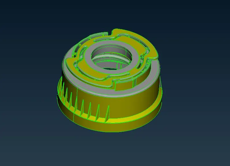
Figure 1: A bottle cap after using topo and adjusting the perimeter and macros to 1mm.
- Geometry Clean-up
Bottlecap when imported in pre-processor software, was very cumbersome and distorted as shown in figure 2. It is because of transferring files from one software to another with a change in the format of the file. It also appears distorted because of graphical changes. The Topo tool was used to reduce some errors. After performing topo, its perimeter and macros nodes are adjusted to 1 mm as shown in figure 1.
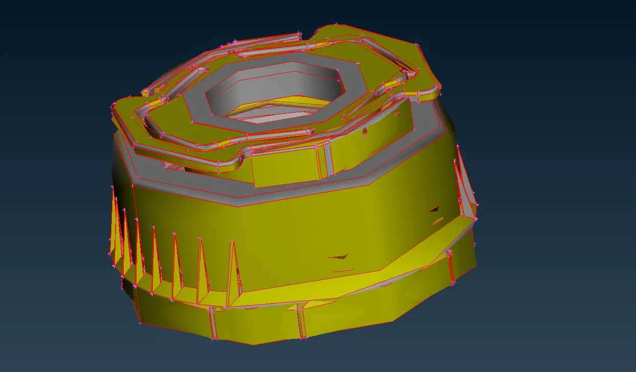
Figure 2: Imported bottle cap geometry.
Geometry can be checked for the presence of any errors using the check manager tool. Figure 4 shows 17 errors in the geometry after performing topo. It includes a single cons error, triple cons error, needle face error, and 4 unchecked faces. Before proceeding to the extraction of the mid-surface of the bottle cap, it is necessary to remove all the errors of the parent geometry. Single con errors generally do not present in a parent geometry. It appears only when there is a free surface. Triple cons errors sometimes need to be present when three surfaces are attached at a single location. However, it is better to check it once manually if it is required one or it is a geometrical error. Needle face is very thin faces present in the geometry which is generally not the part of the geometry or it may get separated while importing the part in the software.
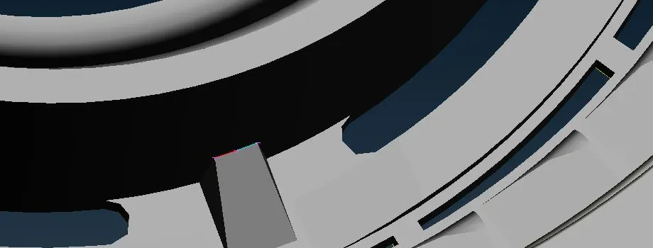
Figure 3: Presence of a single con (in red color) and triple color (in blue color) errors.
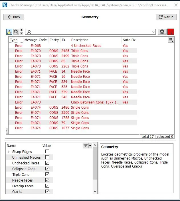
Figure 4: Geometry check for errors using check manager tool.
This error can be removed manually by finding the face and deleting it or it can be removed automatically by using the fix option in the check manager. Similarly, unchecked faces errors can also be fixed automatically. Geometry should also be checked for the presence of any duplicate surfaces. If it is present, it should be deleted. When the geometry is cleaned from errors, its nodes are adjusted to 1 mm to get a fine shape of it. Figure 1 shows the resulted geometry of the bottle cap.
- Auto Mid-Surface
After geometry clean-up, now the geometry is ready for the mid-surface extraction. Mid-surface can be extracted manually or automatically. The geometry is having so many different shapes and features. Therefore, before proceeding to the extraction of mid-surface manually, it is better to check that if auto mid-surface can give a better geometry. If it gives a good geometry then the time is saved and if not then it can be used as a reference in performing manual extraction of mid-surface.
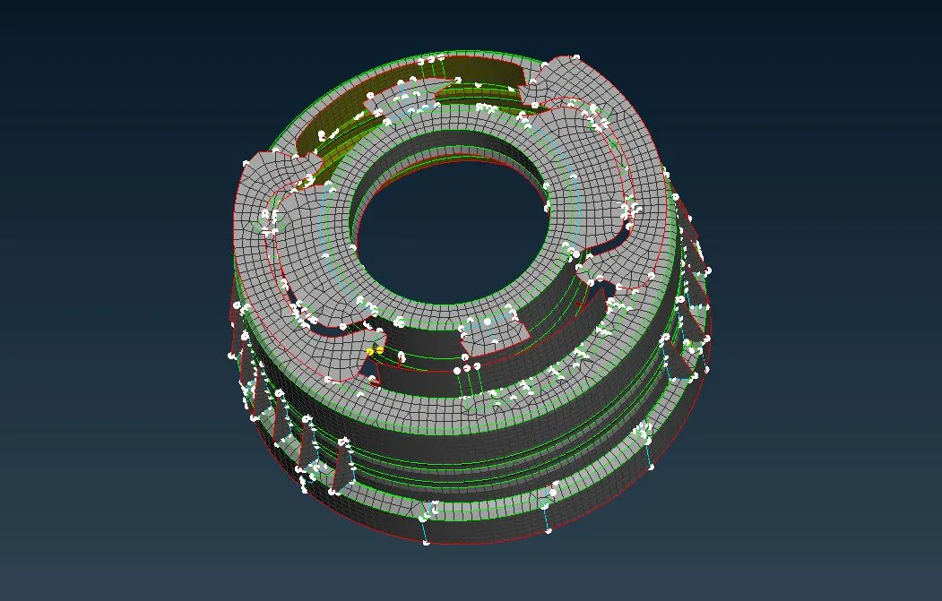
Figure 5: Discretization of geometry using auto mid-surface.
Figure 5 shows the discretization of bottle cap geometry using auto mid-surface. In the figure, it can be seen that the geometry is very much distorted and its shapes are disturbed. Therefore, this discretized geometry cannot be used for further analysis.
- Manual Mid-surface Extraction
Manual mid-surface is generally advisable to perform because using it care has been taken for each and every shape of the geometry precisely. Auto mid-surface has not extracted the mid-surface properly, however, it can be used as a reference in extracting the mid-surface manually. When performing manually, a surface or face is offset to its middle. But a face can have different features like fillets or any curves which might get disturbed while offsetting. To avoid such disturbance, the face is divided into small parts such that offsetting the face successively will not disturb any shape or feature of the geometry. Before performing meshing, a company provides quality parameters for the elements. Table 1 shows the quality criteria with which a geometry needs to mesh.
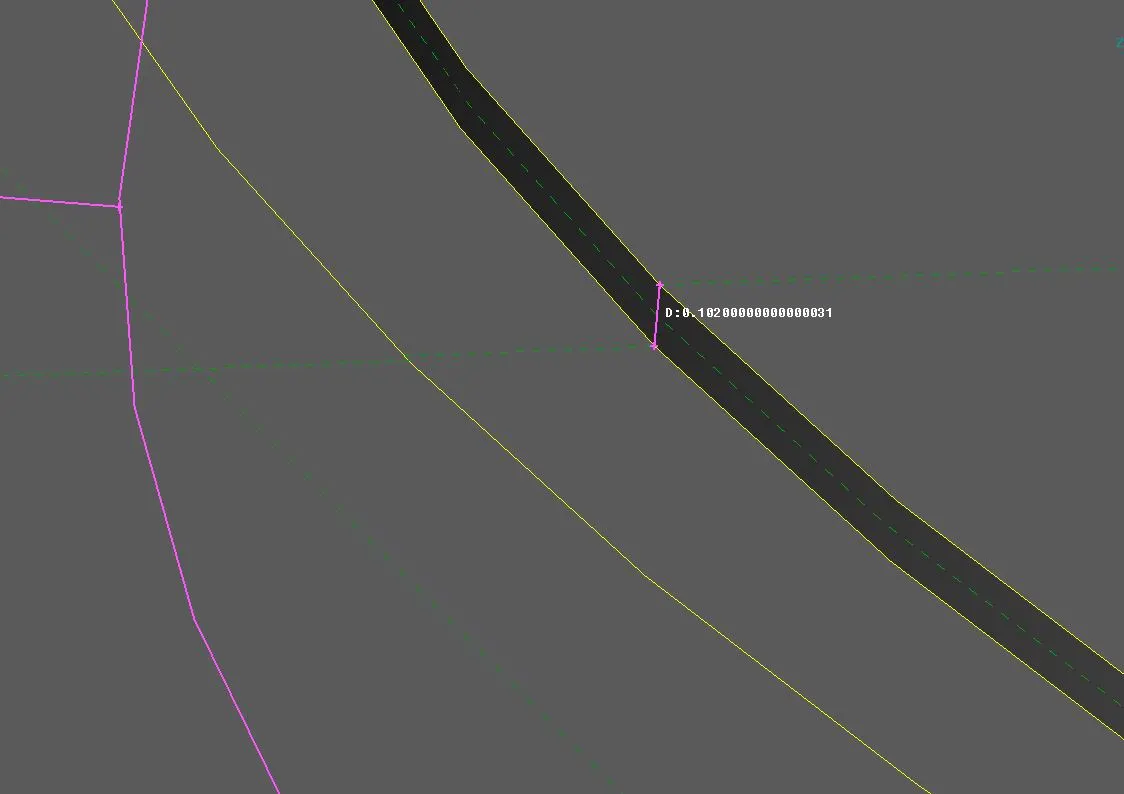
Figure 6: Two double cons of a stepped-up surface with a height of 0.102 mm.
While performing mid-surface extraction, it should be observed that if any geometrical feature is falling below these criteria. If such a case is present then if possible that feature can be neglected. Figure 6 shows an example of such a case, which can be neglected. A surface is always offset in such a way that when a thickness is assigned to the mid surface, it should have taken the shape of the parent geometry. Figure 7a shows the teeth of the geometry whose mid-surface is shown in figure 7b.
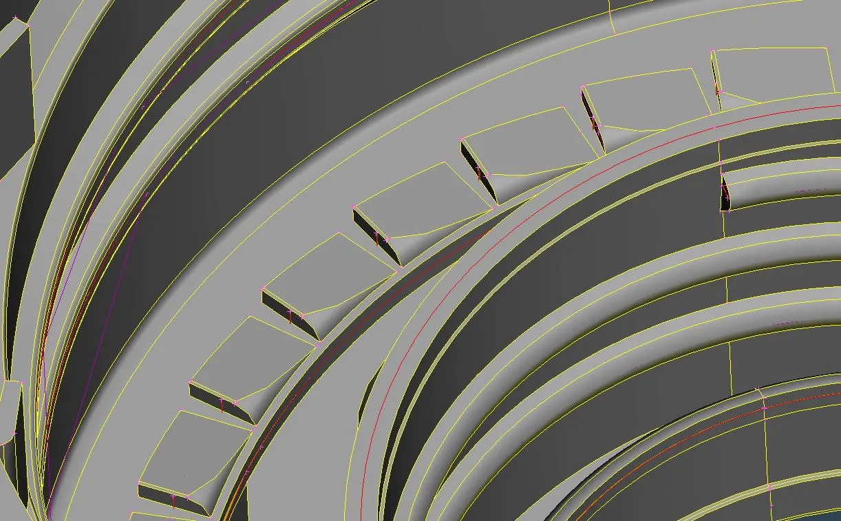
Figure 7a: Teeth of parent geometry.
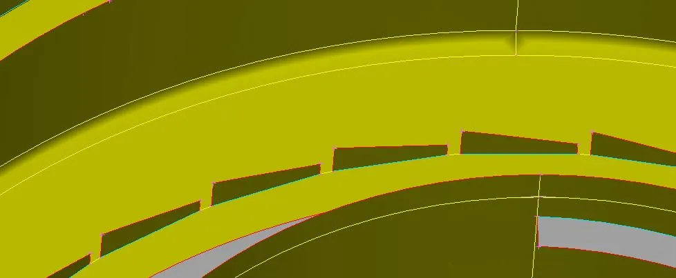
Figure 7b: Mid-surface extracted of teeth.
- Setting Quality Criteria
A company or an individual who wants the discretization of part decides the quality of the element and provides it to the CAE team. Depending on the quality parameters, geometry has meshed. These parameters generally include aspect ratio, target length, the minimum and maximum length of an element, etc. The criteria provided for this part is as shown below table:
| Target/Average length | 1 mm |
| Minimum length | 0.5 mm |
| Maximum length | 3 mm |
| Aspect | 3 |
| Warpage | 15 |
| Skewness | 45 |
| Jacobian | 0.7 |
| Minimum Quad Angle | 45 |
| Maximum Quad Angle | 135 |
| Minimum Tria Angle | 30 |
| Maximum Tria Angle | 120 |
| Tria Percentage | 15% |
- Discretization or Meshing
Meshing a complete geometry gradually needs a good knowledge about elements and it also needs patience. The flow of the elements while meshing complete geometry needs to be maintained. Tria elements are required to be kept minimal. In this work, a 15% allowance is provided for the tria element. Along with this, an element should not fail in criteria. It is because the presence of failed elements in geometry will lead to deviated results. Therefore, failed elements should be corrected, if possible. Figure 8 shows the quality of the meshed geometry. It shows 88 elements are failed and 150 tria elements are present in it. Those elements are present because of geometrical constraints. The complete geometry has 98.5% quad elements and 1.5% tria elements which perfectly fits the criteria. Figure 9 shows the complete meshing of the bottle cap geometry.
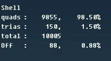
Figure 8: Resulted quality of the manually meshed geometry.
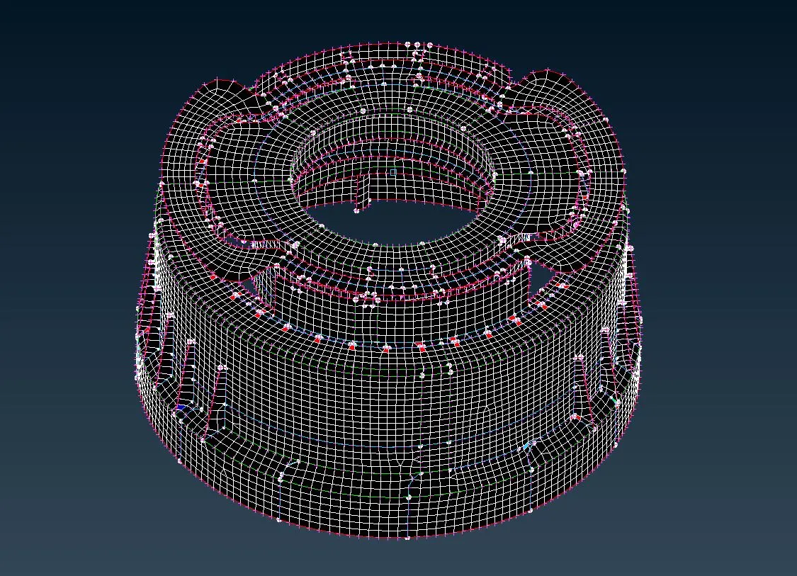
Figure 9: Completely meshed geometry of a bottle cap.
- CONCLUSION
Meshing the geometry is the primary step for performing finite element analysis. Shell mesh is performed using tria and quad elements. Because tria is a stiffer element, it is generally tried to keep as minimum as possible. Secondly, the flow of the elements all over the geometry should be smooth with minimum failed elements.