Use of Morphing Tool on a Sheet Metal Part using ANSA
- INTRODUCTION
Morphing is one of the important tools in ANSA which is used to bring a change in the shape of any part. The importance of the morphing tool can be seen from the example of Datsun company’s GO+ car, which is the extended version of the GO car. A similar example can be seen in the case of Tata’s Indigo and Marina, Hyundai’s i10 and Xcent, Maruti Suzuki’s Swift and Swist Dzire, etc. However, the way to use this tool all depends on one’s creativity along with the knowledge of using it. It can result in a very effective design if a person is aware of the way to use it.
A morphed part is not considered as the final product to be manufactured, however, it brings in the new idea that can be put into, to bring some significant changes. It gives a new idea to a design engineer, to make possible changes and to make a more effective product. In this work, a morphing tool is used on a sheet metal part to understand the way of using it and see how effective it can be.
Aim
To use the morphing tools on a sheet metal part.
Objective
To study and understand the way of using the morphing tools.
- PROCEDURE
Before initiating the procedure to use the morphing tools, firstly, it was required to clean the geometry imported, as shown in fig. 1. Morphing tools can be used on CAD geometry or the FE model. Here, in this work, it was used on a CAD model. When the geometry was imported it was full of errors present in it. Therefore, it had to clean before proceeding with any further procedure.
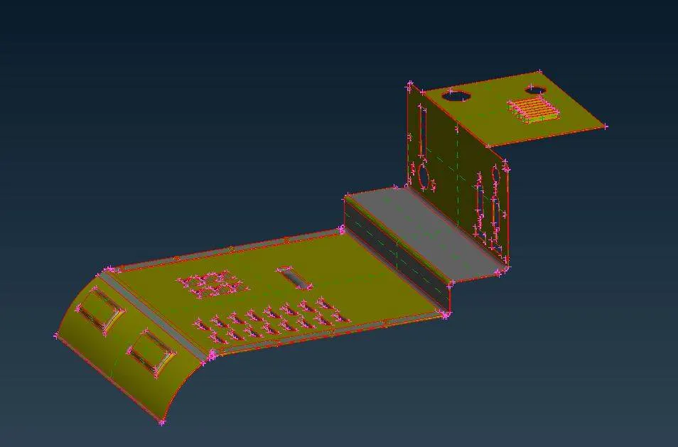
Figure 1: Sheet metal part is taken to study the morphing tools.
To rectify the errors, a command was given to join all the neighboring cons, using the ‘Faces>Topo’ tool, in the TOPO deck. Though the ‘Topo’ tool was used to clean some errors, it was still having some triple cons errors present near the bolt stem. Fig. 2 shows the presence of triple cons errors. Those errors were eliminated manually.
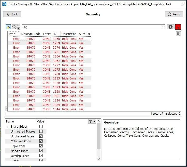
Figure 2: Geometry check manager indicating the presence of triple cons errors.
Now, when the geometry was free from all errors, it was ready to try the morphing tools on it. As shown in fig. 3., the green icon, marked in the red circle, is the morphing deck icon. Once it is selected, the morphing window gets active which is also indicated at the right-down corner, in working space, as shown in fig. 4.
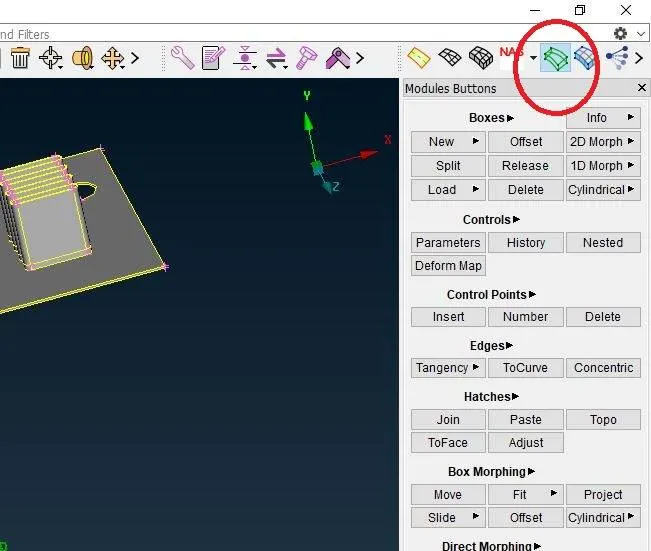
Figure 3: Morphing deck icon is shown in the red-colored circle.
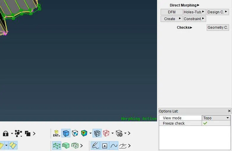
Figure 4: Window showing that morphing deck is active.
As said earlier, morphing tools are used to change the shape of the design irrespective of its dimensions available. Therefore, to change the shape of any part of the complete body, it has to be brought in a morphing box. A morphing box is a cubical region within which if a body is kept, that particular region only will go under shape change and the rest of the shape of the design will remain as it is. In the morphing deck and boxes section, the ‘New’ option is used to create the box. When the ‘New’ is selected a window opens as shown in fig. 5. In that window, geometry has to be selected, and ortho has to be selected as the box type.
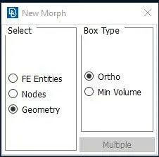
Figure 5: Window to create the morphing box.
After selecting the options, a specific region of the geometry has to be selected to which shape has to be made, as shown in fig. 6. Once selected and hit enter, a green-colored box gets created as shown in fig. 7. The green-colored box is the morphing box. The shape change would occur in that specific region only to which box has enclosed.
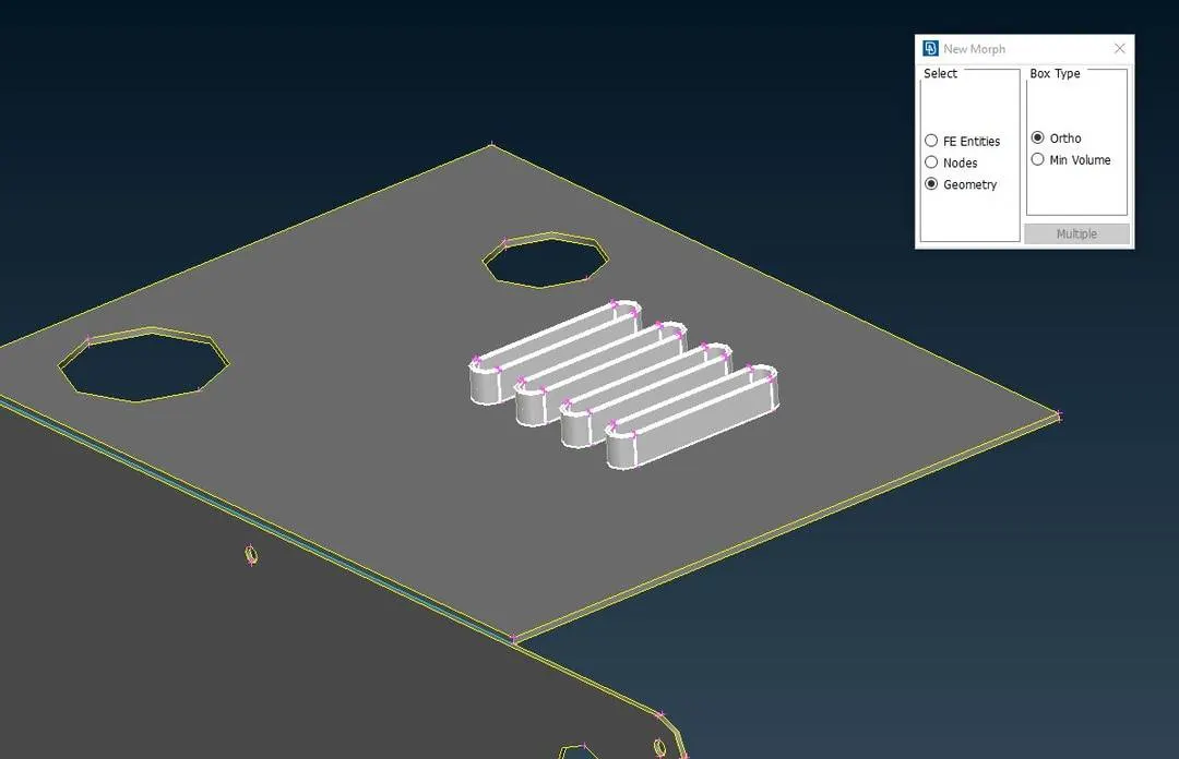
Figure 6: Selection made to change the shape.
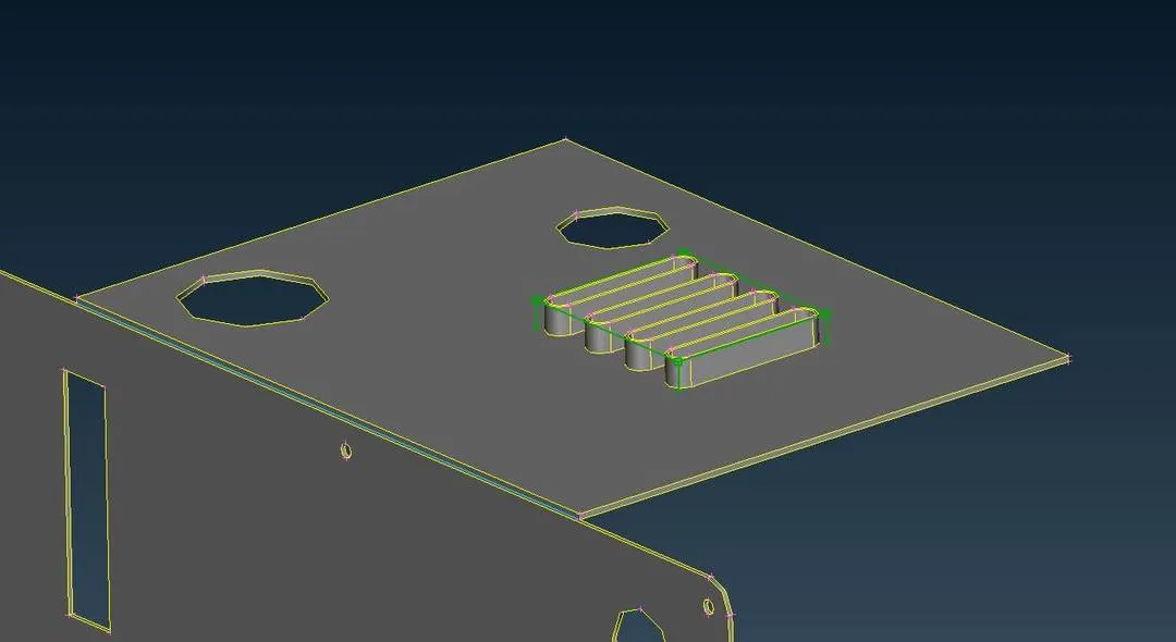
Figure 7: Meshing of the component using the batch mesh method.
Now to bring changes in the shape of the design, in the ‘Box Morphing’ section, ‘Move’ is there. When the ‘Move’ option is selected a window would appear, as shown in fig. 8, which asks about the points of the box which has to be moved. Therefore, the nodal points have to be selected by whose selection desired shape change would come. In this work, nodal points that were selected are shown in fig. 9.
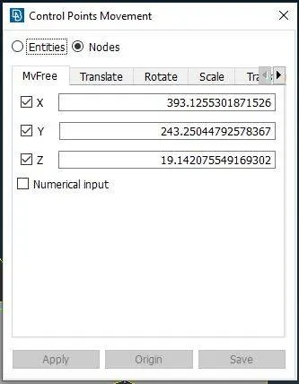
Figure 8: Window opened after selecting the ‘Move’ option.
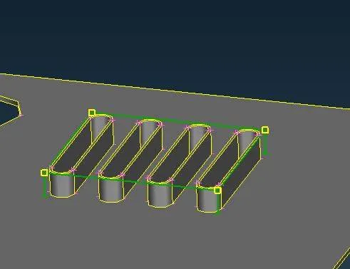
Figure 9: Selection of four nodal points, represented by yellow color.
When hit enter, by clicking the middle mouse key, it results in free movement. Any shape can be given to that specific region. When it becomes sure that which shape has to be kept, hitting enter would result in the final shape change of that region. It appears as shown in fig. 10.
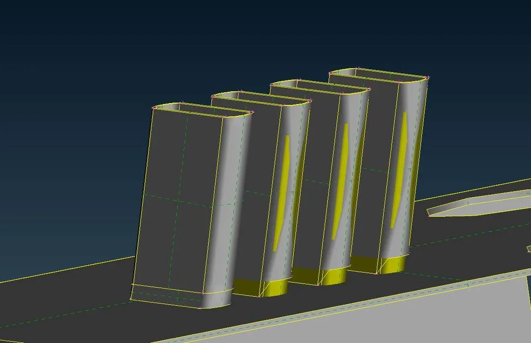
Figure 10: Morphed feature of the geometry.
In fig. 10, it can also be seen that the base of the first feature appears good-looking, however, the other three are still having distortion at their bases. Shape change would result in some geometric distortions which can be corrected manually. The box created to change the shape can also be split to create more nodal points to bring more effective shape change, using the ‘Split’ tool in the boxes section. The split box is shown in fig.11.
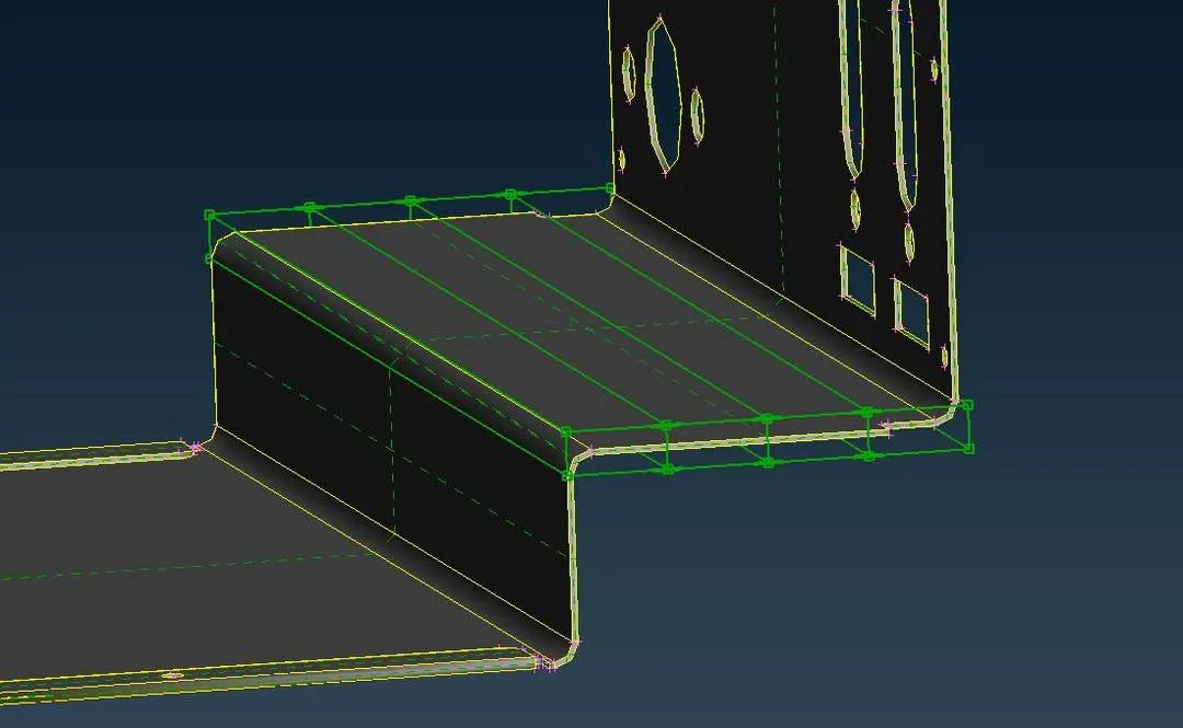
Figure 11: The morphing box was split, creating 12 more nodal points, to make more changes.
Using those extra nodal points, more shape changes were brought into the geometry and it started appearing as shown in fig. 12.
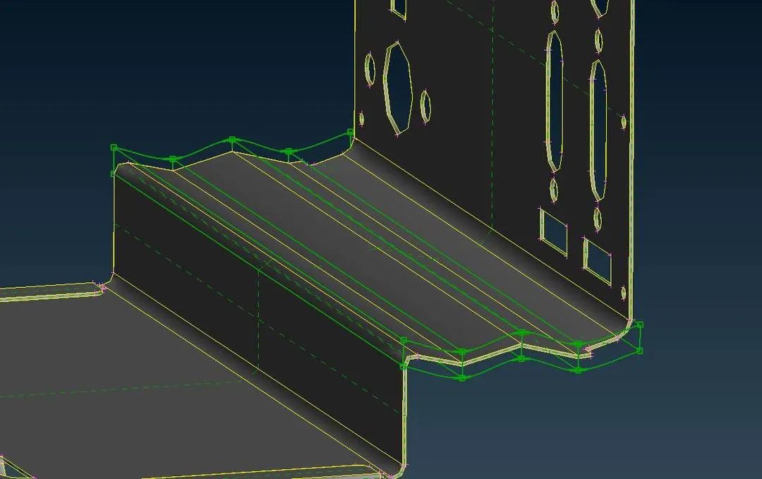
Figure 12: Shape change brought into geometry, using more nodal points.
- LEARNING OUTCOME
- Morphing a geometry or FE model doesn’t require the dimension to bring some changes in the design.
- Morphing any product could result in some geometric distortions, therefore, it has to be corrected manually.
- A morphing tool could result in a good tool to bring some effective design change in a product if one has both the knowledge of using the tool and creativity.
- Morphing could give an idea to think about the way to change the shape.
- CONCLUSION
The morphing tool is used to change the shape of the design of any part, to get the general idea of the changes that can be made that could bring a more effective performance or can give good aesthetics.