Week 5.3 - Forced convection Analysis
Aim: To do a forced Convection analysis of a DME model by converting it into an ICEPAK model.
Objectives:
1. To convert the CAD Model into an ICEPAK Model.
2. To set up a case for the Forced Convection Analysis.
3. To do postprocessing of the results.
A New Project is created as given below:
ANSYS DesignModeler is opened through ANSYS Workbench.
A Geometry (ANSYS DesignModeler) component module from the Toolbox is dragged and dropped on the
Project Schematic window as shown below:
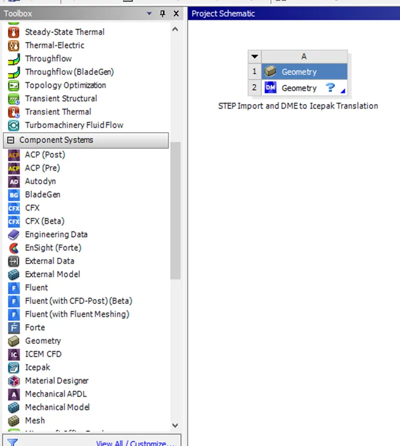
The Geometry component module is renamed to STEP Import and DME to Icepak Translation as shown in the picture above.
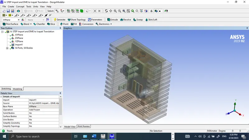
By Right clicking on the Geometry component cell A2 Design Modeler is selected, its default length unit is changed to mm, and the DME.stp model is imported for further modification.
The imported model is shown below:
Now editing the Model for ANSYS Icepak:
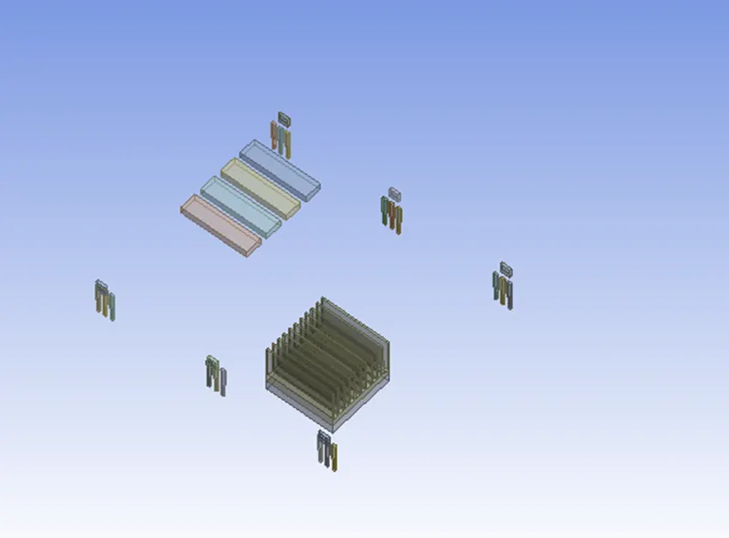
Using Show Ice Bodies from Electronics options, bodies with simple geometries are recognized as ANSYS Icepak objects.
Bodies Recognized as ANSYS Icepak Objects
Bodies not Recognized as ANSYS Icepak Objects
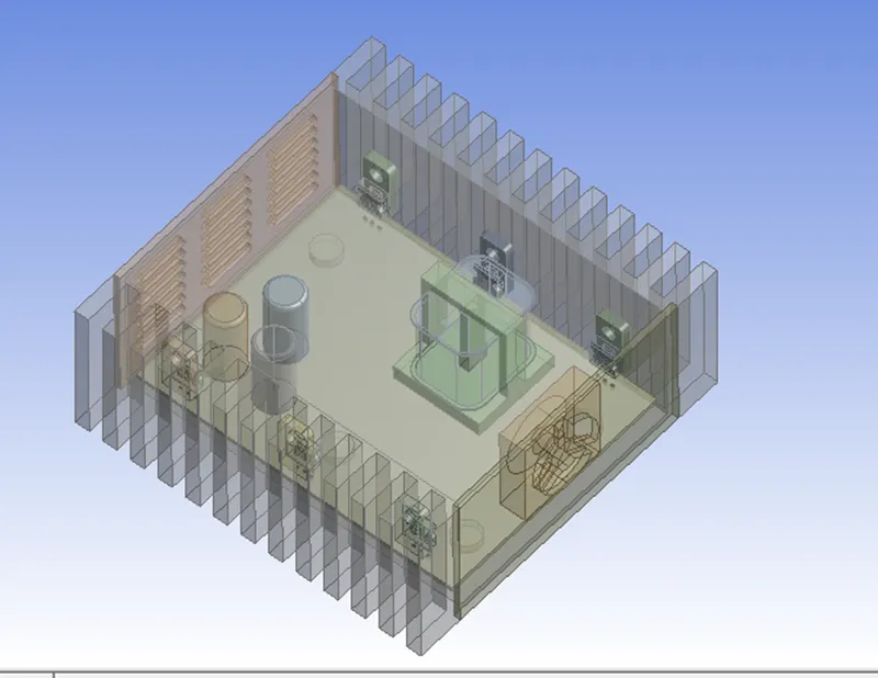
These are the bodies that have to be modified in order to export these bodies into ANSYS Icepak.
FinsSlice1 Face Selection
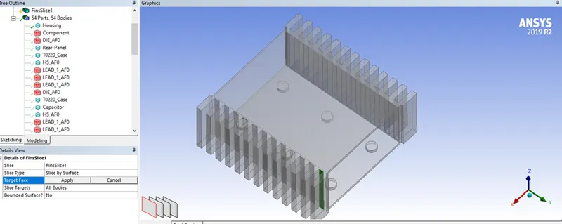
Details View of FinsSlice1
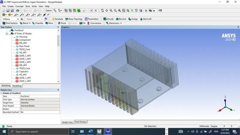
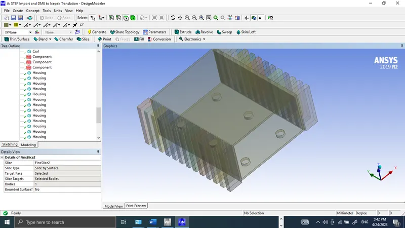
FinsSlice2 Bodies are shown below:
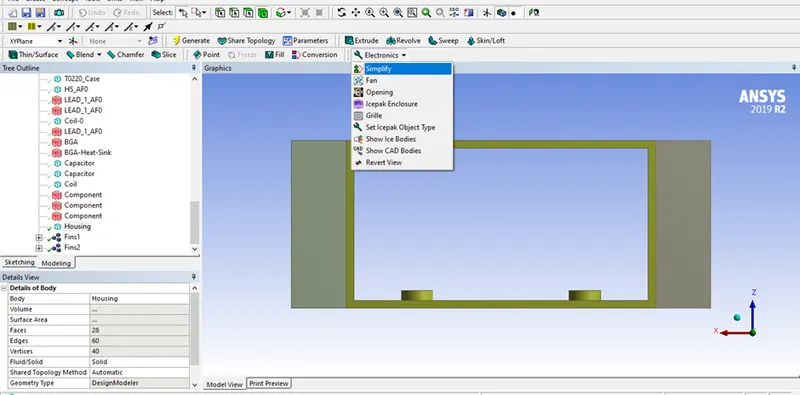
SimplifyingSimplifying the Housing body between the parts Fins1 and Fins2:
Simplify option is selected from Electronics
Simplified bodies are shown below:
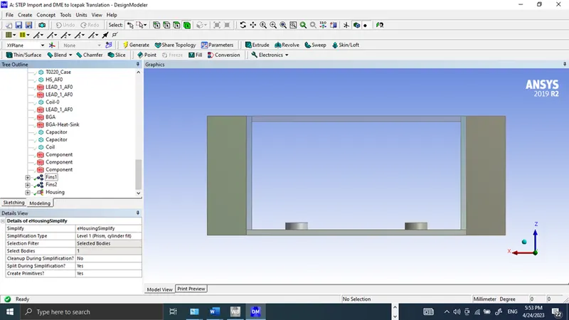 Creating openings for the fan and the back panel
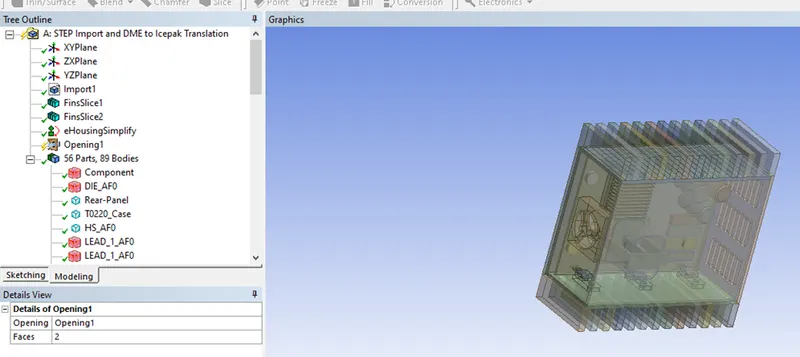
By selecting +Y, and -Y direction faces as shown below, the Opening from Electronics option is chosen to create fan and back panel openings.
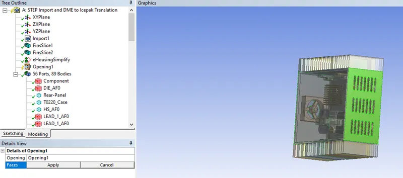
Created openings are shown below:
Creating a Fan
The fan body is selected from Tree Outline, and then Fan options are selected from Electronics as shown below:
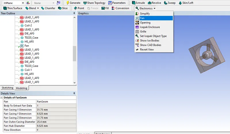
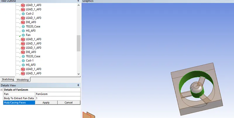
The faces shown in the image below are selected to extract the fan geometry parameters.
Hub/Casing Faces Selection:
Adding the fan to the Front-Panel part:
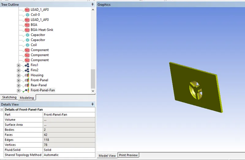
In the Tree Outline, the Front-Panel part is selected, and then simultaneously while pressing Ctrl the
The Fan object is clicked.
By Right-clicking the Fan object Form New Part is selected.
In the Details view, the Front-Panel Part is renamed to Front-Panel-Fan.
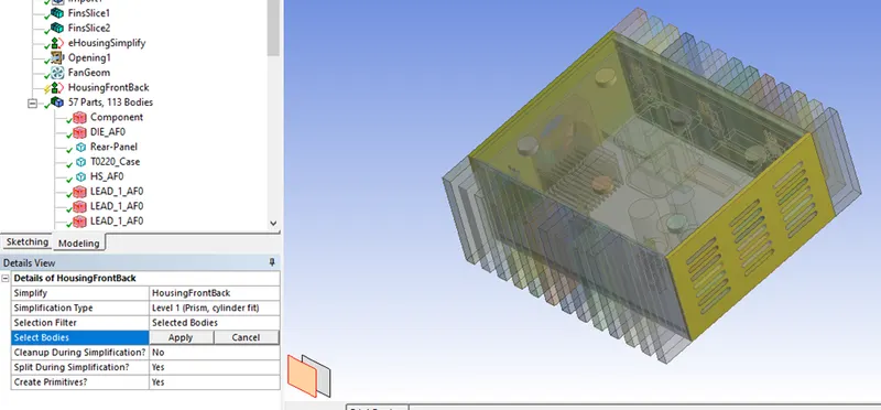
Perform a Simplify operation on the Housing:
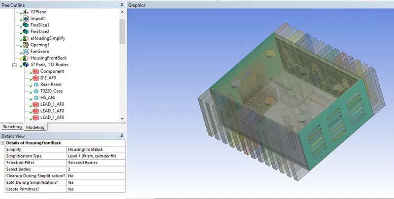
The front and rear panel of the housing is selected to simply them into Ice bodies.
Simplified front and rear panels are shown below:
Performing a Simplify operation on the PWB and the T0220 objects:
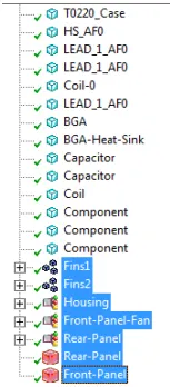
All the Housing, Fin, Panel, Opening, and Fan objects from the bottom of the Tree Outline are selected and hidden.
Selection of Housings, Fins, Panels, Openings, and Fans
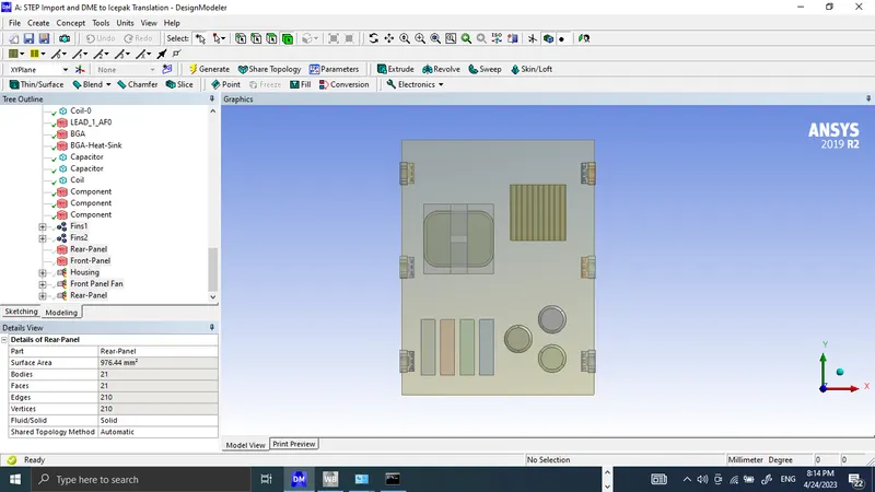
Internal components only:
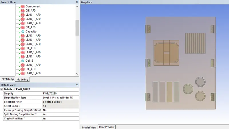
Simplified PWB and the T0220 objects:
Adding all the package objects to the Parts:
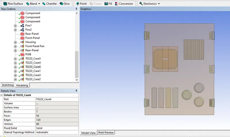
Parts are selected, and Form New Part is used to combine them together and renamed as shown in the above picture.
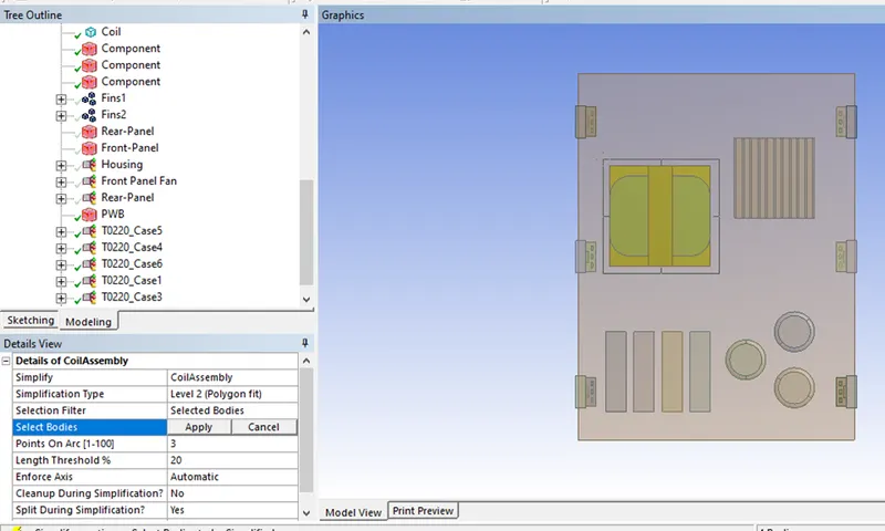
Performing a Simplify on the Coil:
The coil bodies are selected as shown below, and simplification is performed.
Coil Bodies Selection:
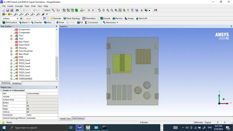
Adding the rest of the Coil bodies to the part:
all remaining coil bodies (8 bodies) are selected and combined together as CoilAssembly2. It is shown in the image given below:
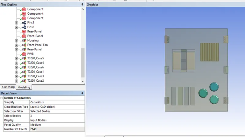
Performing a Simplify on the Capacitors:
Capacitors Bodies are selected and simplify is performed for level 3 simplification, later 3 capacitors are combined together and named as Capacitors.
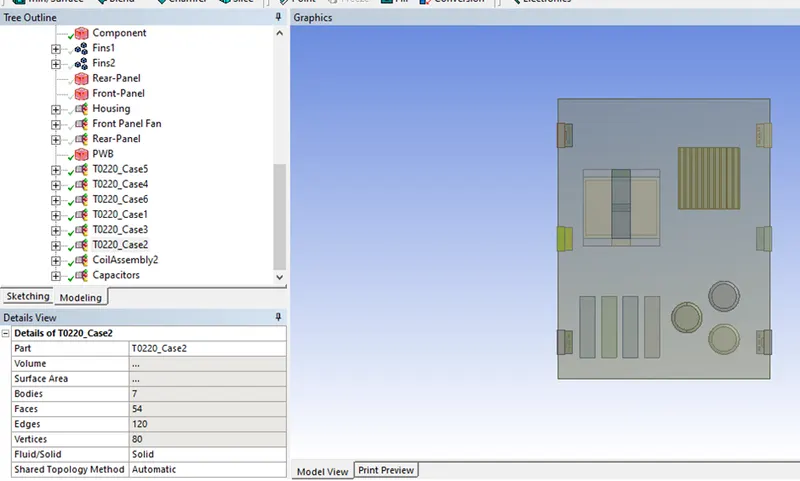
Capacitors Assembly as shown below:
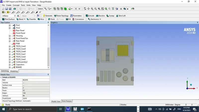
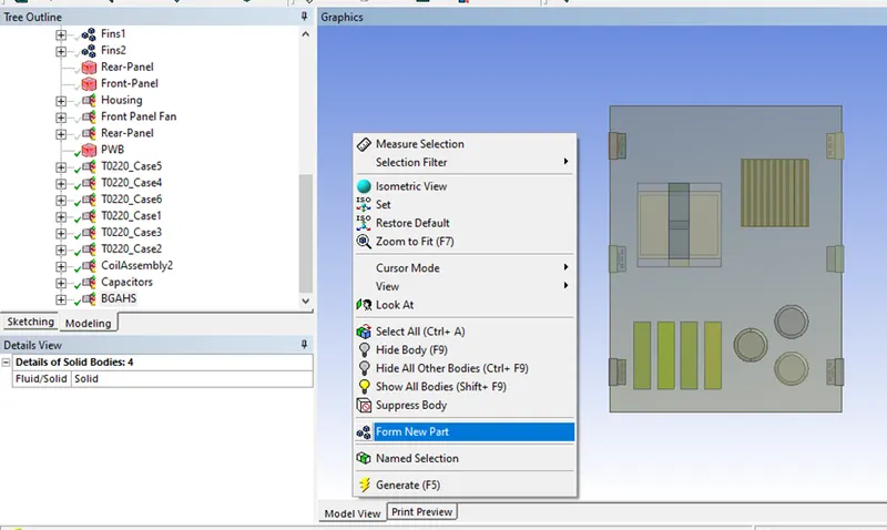
Forming parts for the Heat Sink and Components:
Selection for BGAHS as given below:
Selection for Components as given below:
Final Model in ANSYS DesignModeler as shown below:
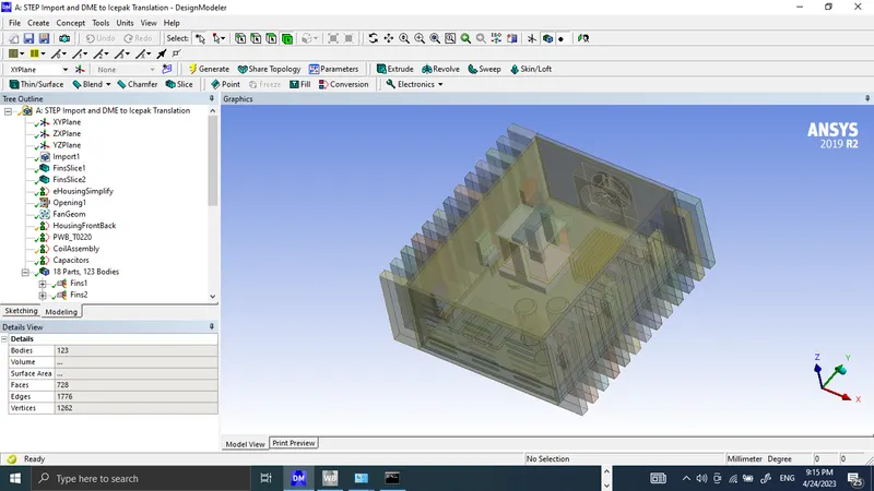
The model is now ready to use in ANSYS Icepak.
Opening the Model in ANSYS Icepak
Creating an ANSYS Icepak Component Module:
In the ANSYS Workbench, an ANSYS Icepak component is dragged to cell A2 to create an ANSYS Icepak component module.
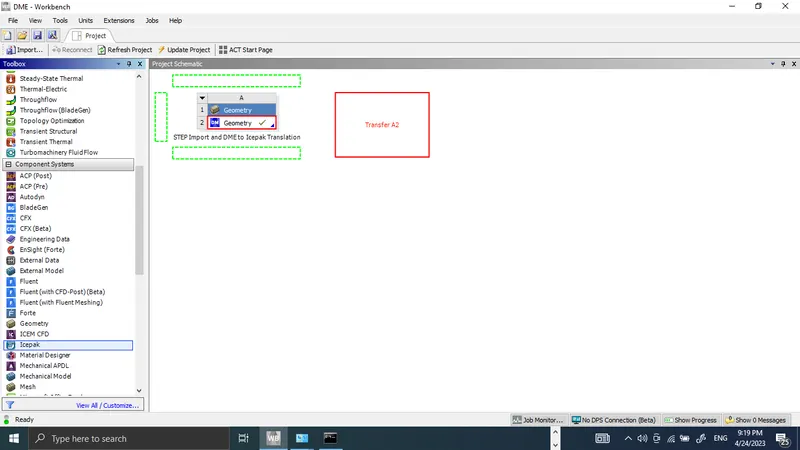
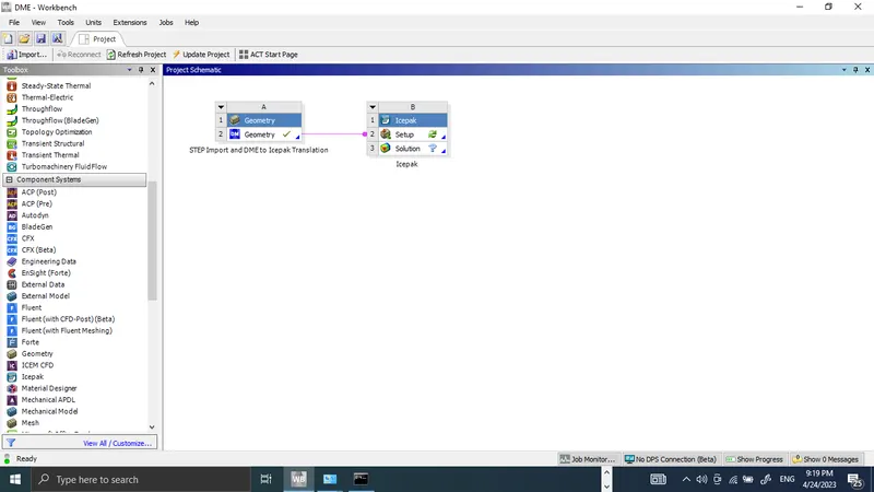
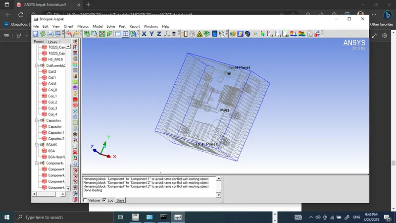
By double-clicking the Setup cell (B2) the model is opened in ANSYS Icepak.
In the Model Manager window, by right-clicking the Model node and by selecting Expand all the geometry
inside the assemblies is viewed.
Preparing Model for Meshing:
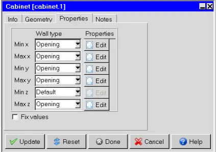
Before preparing the model for non-conformal meshing, the cabinet is autoscaled to cover the entire model.
The boundary condition is applied to the cabinet walls.
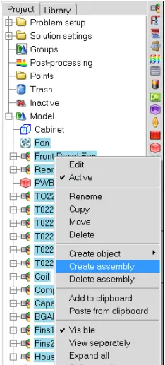
An assembly is created by selecting assemblies and other Ice bodies, as shown below:
Slack Settings and Max Element Size Inputs for above-created assembly are given below:
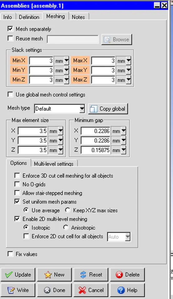
Slack settings used for other assemblies are tabulated below:
| Assemblies | Min X | Max X | Min Y | Max Y | Min Z | Max Z |
| Front-Panel-Fan | 0 | 0 | 1 | 1 | 1 | 1 |
| Rear-Panel | 0 | 0 | 1 | 1 | 1 | 1 |
| T0220_Case3 | 1 | 1 | 2.23 | 1 | 1 | 1 |
| T0220_Case2 | 1 | 1 | 1 | 1 | 1 | 1 |
| T0220_Case1 | 1 | 1 | 1 | 1 | 1 | 1 |
| T0220_Case4 | 1 | 1 | 2.23 | 1 | 1 | 1 |
| T0220_Case5 | 1 | 1 | 1 | 1 | 1 | 1 |
| T0220_Case6 | 1 | 1 | 1 | 1 | 1 | 1 |
| CoilAssembly2 | 1 | 1 | 1 | 1 | 4.175 | 1 |
| Components | 1 | 1 | 1 | 1 | 4.175 | 1 |
| Capacitors | 1 | 1 | 2.271 | 1 | 4.175 | 2 |
| BGAHS | 1 | 1 | 1 | 1 | 4.175 | 1 |
| Fins1 | 1 | 0 | 1 | 1 | 1 | 1 |
| Fins2 | 0 | 1 | 1 | 1 | 1 | 1 |
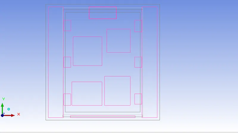
The model after filling slack values and opting for mesh assemblies separately is given below, housing will be based separately.
Now mesh is generated by using values given in the mesh control panel, other values are kept as default.
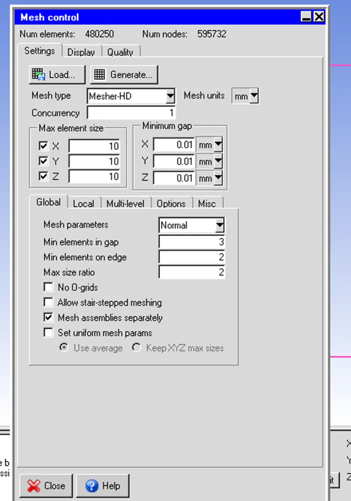
Generated mesh has 480250 elements and 595732 Nodes.
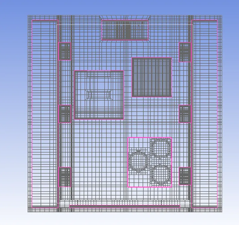
Z Plane through the Center
Y Plane through the Center
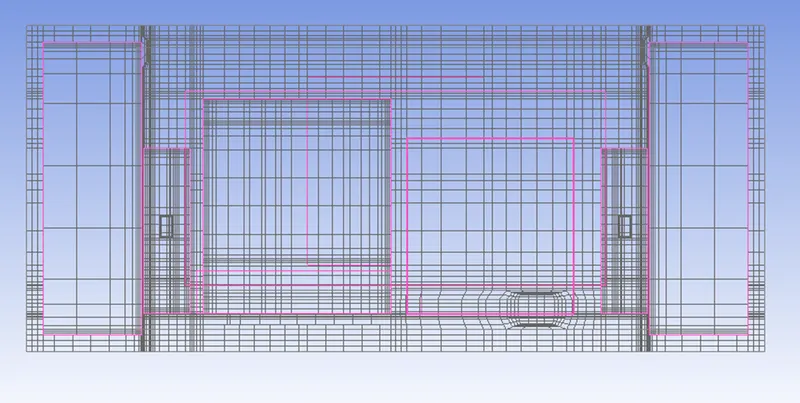
X Plane through the center
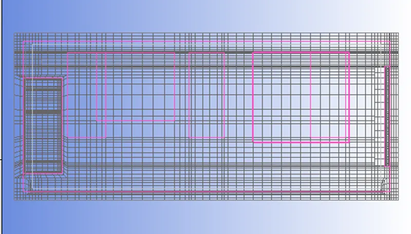
From visual inspection, the mesh seems to be good enough for getting a first-cut solution.
Power and Material Inputs:
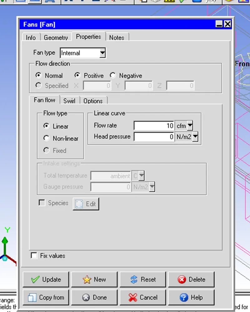
BGA component material is chosen as ceramic_material, Power loss is assigned as 25 watts, each transformer coils as 2 watts, and material for coils is selected as Cu-Brass, each capacitor is assigned mold_material and 5-watts power loss. The fan setting is shown below:
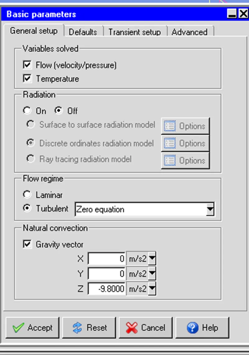
Problem Setup:
Flow and temperature variables are to be solved. The radiation effect is off.
Solver Setup:
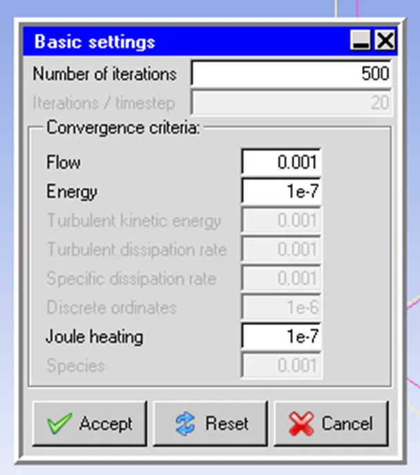
The solution is to be run for 500 iterations, Parallel, and Advanced settings are kept as default.
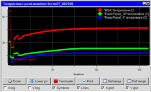
A monitor point is created on the BGA component, to monitor its temperature.
Solution Residuals as shown below:
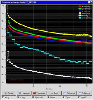
The solution converges after 150 iterations.
The temperature monitor plot for BGA is given below:
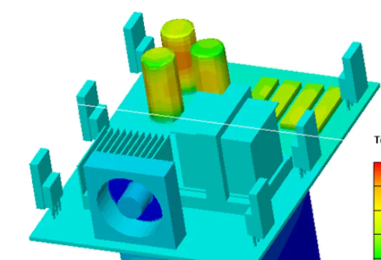
Display Contours of Temperature on Selected Objects
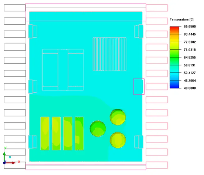
The maximum temperature achieved is 89.6509, as shown in the plot above.
Object face as shown below:
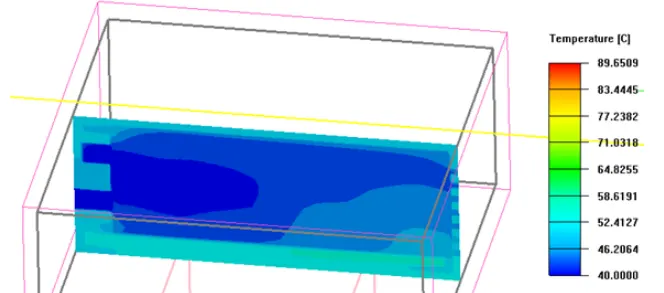
Plane Cut of Temperature Contours
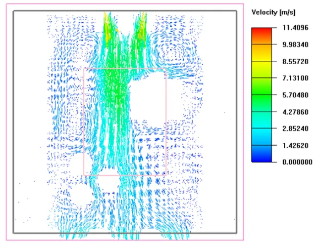
Plane Cut of Velocity Vectors:
From the above plot, it is observed that maximum velocity occurs near the fan i.e. 11.4096 m/s.
we can observe the convection current forming in the model which helps in the proper dissipation of heat.
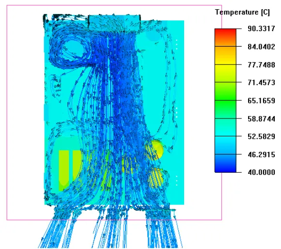
The above particle trace shows how air streams are flowing in the model, and helping in heat dissipation.
Conclusion:
The given CAD model is imported and converted to the Ansys ICEPAK object successfully.
Non-conformal mesh is generated by using proper slack values.
The residual plot shows the solution is conversing after 150 iterations.
BGA attains the maximum temperature.