Week - 5 - 2D meshing for Plastic components
OBJECTIVES- To extract the mid surface and mesh the given bottle cap component using the given quality criteria and assign correct thickness to the property.
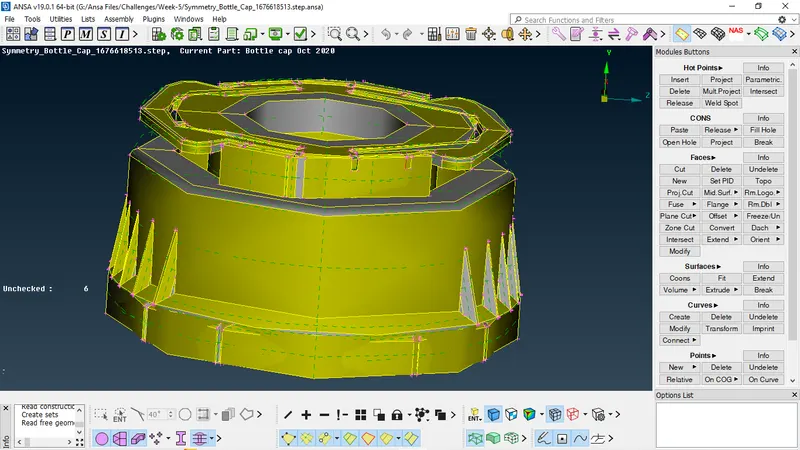
CAD MODEL IMAGE-
PROCEDURE -
First import the CAD Model of PLASTIC BOTTLE CAP into ANSA Software or interface, then perform an initial Geometry checkup in this procedure we need to check for the following Geometrical errors present in the model like crack, overlap face, needle face, triple con, unchecked faces etc.
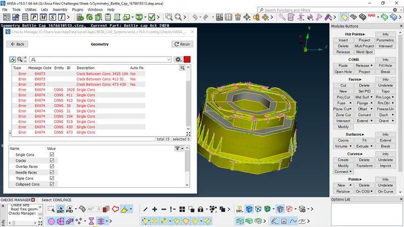
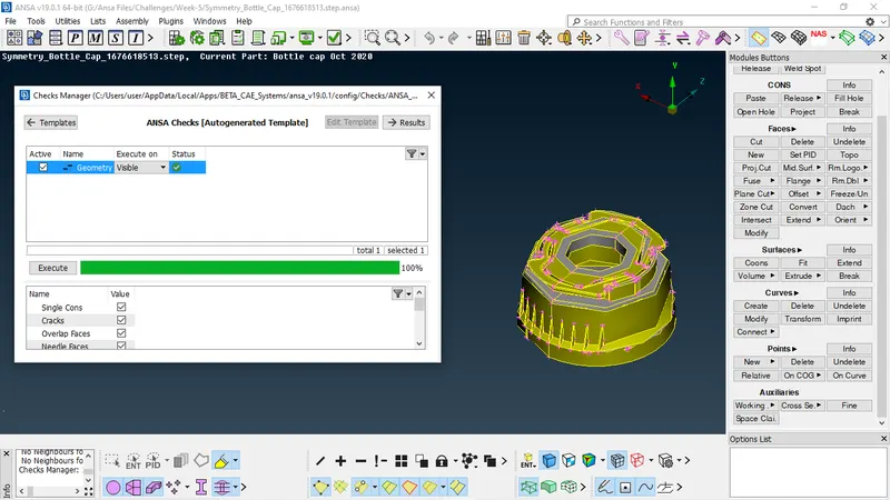
After the checkup fixing the errors if any, we can achieve this either by Manually or Autofix, hence all the CAD models were check for clean geometry and all their surface imperfections are fixed in the geometry check. after this procedure, geometry is free from error as we can see in below image.
Then Orient command is used to check the orientation is proper in all the faces of the CAD geometry.
MIDSURFACE GENERATION-
Before extracting the Mid surface of the components, its important to measure their thickness. And this can be achieved by using the command Measure. And by chosing the end of two hotpoints we can get the thickness of the geometry. so we can create Midusrface for each different surface manually.
As we know that there are different options are available to generate midsurface, soa as per requirement we can use any option to create midsurface.

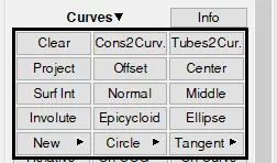
As this component is very small and complex automatic option may generate bad midsurface for this type of component. so for this model we will generate midsurface manually for each surface.
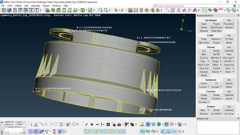
As the thickness varies from surface to surface, we will create the PID for each midsurface or particular group of midsurface and apply the thickness to them.
There are some surfaces with variable thickness, which cannot be directly offset. For those areas, we can generate the midsurface by different methods as below:
INNER FEATURES-
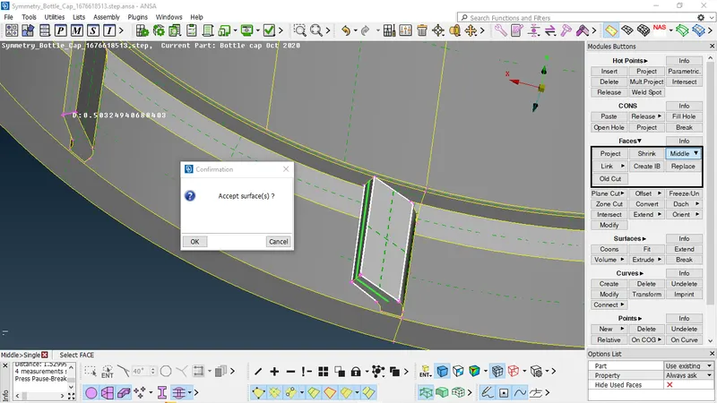
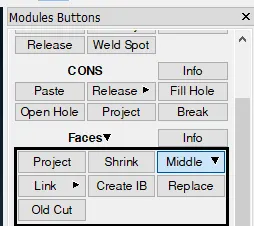
As we can see that feature is varying in thickness, so for that we can use FACES - MIDDLE option to generate midsurface. we just need to select the both the surfaces and by pressing middle mouse button, midsurface is generated.
TEETH-
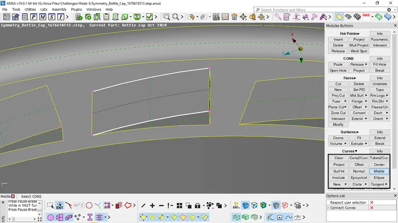
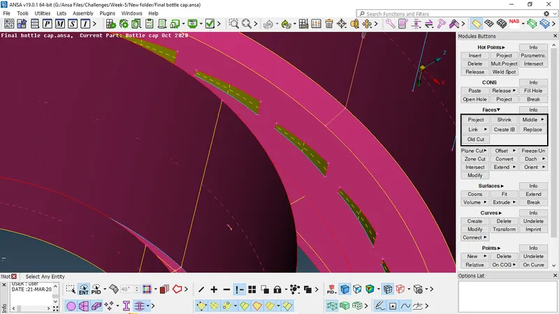
Here we can create a middle curve, CURVE - MIDDLE and then by projecting that curve to the midsurface of body and by creating a new surface with help of CONS, we can finally create a midsurface for the teeth.
RIBS-
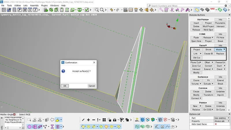
As we can see that feature is varying in thickness, so for that we can use FACES - MIDDLE option to generate midsurface. we just need to select the both the surfaces and by pressing middle mouse button, midsurface is generated.
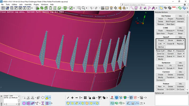
While creation of midsurface, create PID using SetPID option and give appropriate thickness to relavent midsurface for actual presentation.
QUALITY CRITERIA SETUP AND MESH PARAMETERS-
Once the Mid surface is generated, the CAD model is now ready for the meshnig, and for that we need to assigned the quality parameter and mesh attributes, the quality criteria for the mesh is defined using the command Quality Criteria ( by clicking F11 )
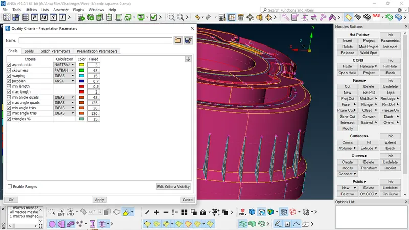
Then switch to Presentation parameters tab, In Graphics division put tick mark for Elements% and choose the Details on demand effect as 'More details'.
Then Click on the Mesh parameters and give the following values mention below
- Target Length = 1
- Min Length = 0.5
- Max Length = 3
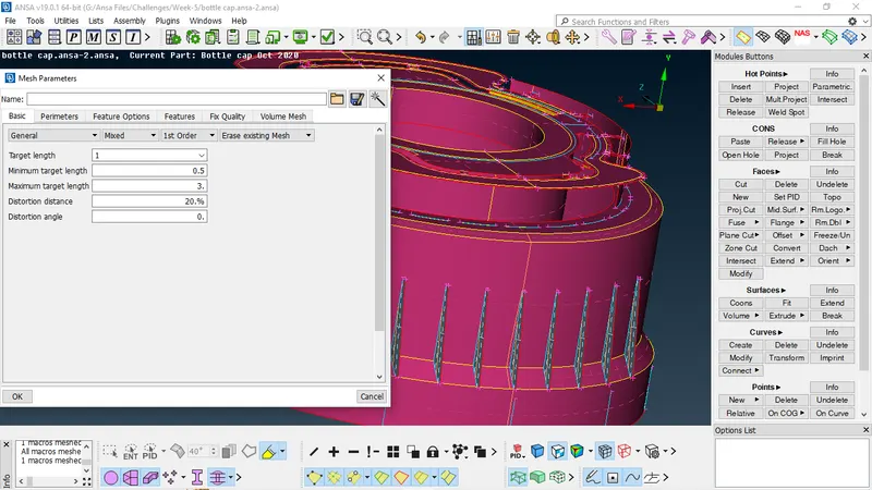
After puting all the values now click on the Perimeters - Length command and choose the entire component and give the target length of the mesh value as 1. (Given in question). The same should be also done for the Macro. then the component should be checked for Defeaturing, in this we usually suppressing the near by cons which tend to fail the Quality criteria.
MESH GENERATION AND QUALITY IMPROVEMENT-
BEST command is used to Generate Mesh (its basically the process of discretizing Model into small numbers of elements), in this we just need to select the face, then clicking on the BEST Mesh command and pressing the middle mouse button to Generate mesh.
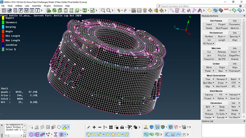
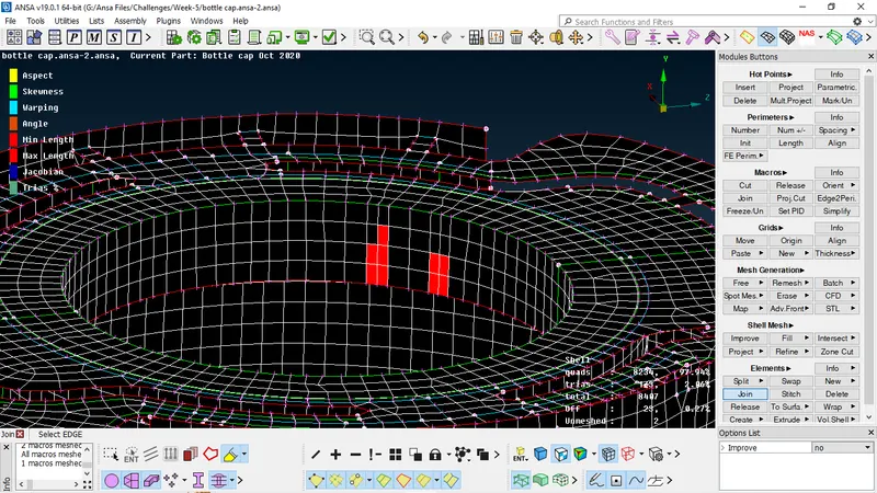
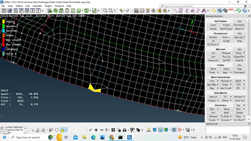
While meshing, we can see in above image, that there are some bad elements near triple cons, so we need to improve the quality for good mesh flow, for that Quality check is performed on the generated mesh. Mesh is adjusted in such a way that it follows the required quality criteria. some areas, even reconstructing the mesh is not enough to get good mesh.
SPLIT, SWAP, JOIN, These commands are used to move Trias, away from the position, it also reshaped Tria elements, so by using these commands we can eleminate Trias from our model and hence the comdition can also be achieved.
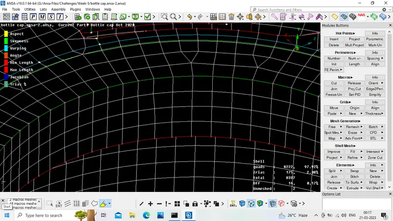
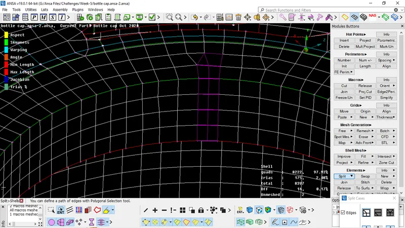
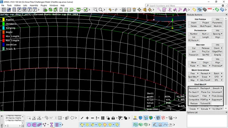
Similarly, RECONSTRUCT, IMPROVE, SMOOTH are used to obtain smooth mesh flow element in model.
After completion of meshing, go to QUALITY CRITERIA - PRESENTATION PARAMEERS - DRAW SHELL AS SOLID. We can see in above image, with this option we can see all elements in 3D form or as solid. Thus the 2D mesh will be displayed as solid mesh according to given thickness of each midsurface.
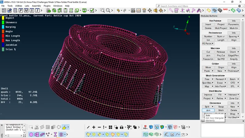
We can see in above image, with this option we can see all elements in 3D form or as solid, and after that we can check or compare the 3D presentation of 2D mesh and actual 3D model without mesh.
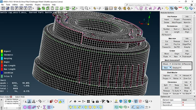
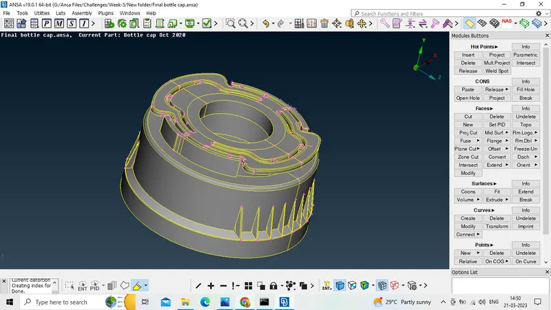
So here we can conclude that we can make the mesh model more accurate as the 3D geometry and we can get accurate analysis results with good quality mesh.
FINAL MODEL IMAGE
RESULT-
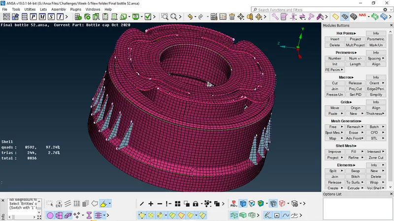
Cuts and join operations were performend, hot points were added removed as required to obtain the uniform mesh as much as possible. Final mesh obtained was error free except only near the triple cons region, else satisfies all the required quality criteria given in the question. therefore the cad model of PLASTIC BOTTLE CAP is ready for further analysis.
- From the quality criteria we can observe the number of total elements in the mesh model is 8836.
- And number of tria elements are 244
- So here the Tria % = 2.76%