Week 3 - 2D meshing for Sheet metal
OBJECTIVE-
TO Mesh Hood as per the given quality Criteria.
CAD MODEL IMAGE-
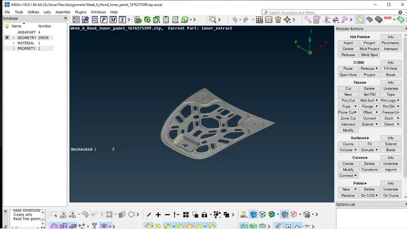
PROCEDURE-
During this project I followed the following steps.
- Geometry Cleanup
- Topology
- Midsuraface Generation by using Offset method
- PID setup for Midsurface
- Quality Criteria Setup and mesh Generation
- Quality imrovement of mesh flow
Geometry Cleanup-
First step is to import the CAD model and then we go for geometry checkup,in this procedure we need to check for the following Geometrical errors present inthe model like crack, overlap face, needle face,triple con, unchecked face etc we can do geometric checkup clicking on the TOOLS on the toolbar menue, and simplyclick on the Geometry.
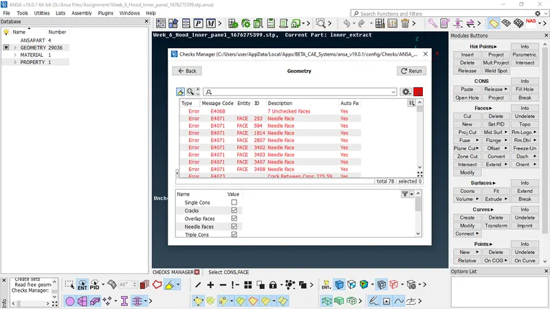
After the check up as we see thee are following errors presnet in the model we can fix these errors either Autofix option by right click of mouse or Manually, For Manual just right click on the error and press the show only option this we can fix it.
TOPOLOGY-
In this we perform topo and then set the perimeter and macrons lengths as per the quality criteria.
MIDSURFACE GENERATION-
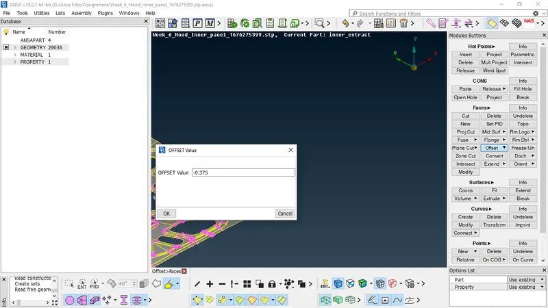
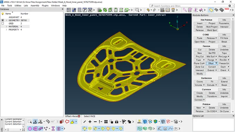
For midsurface i used offset command its basically the layer between two surfaces , as the thickness of sheetmetal is 0.75 i take midsurface at 0.375, by clicking on the offset command and by using Feature Area i selected the whole body after putting the midsurface value and clicking the mouse middle button midsurface is generated in this the direction of arrow is important the value of midsurface depends on the direction for which offset value is being taken and positive or negative sign added before value. we can also use Automid (Midsurface) option. but For this project i use offset method.
PID SETUP FOR MIDSURFACE-
After Generating the Midsurface we need to assign properties for the midsurface in that we have to put the values of thickness and material, for that first click on the PID set properties and select faces and by right click select Apply.
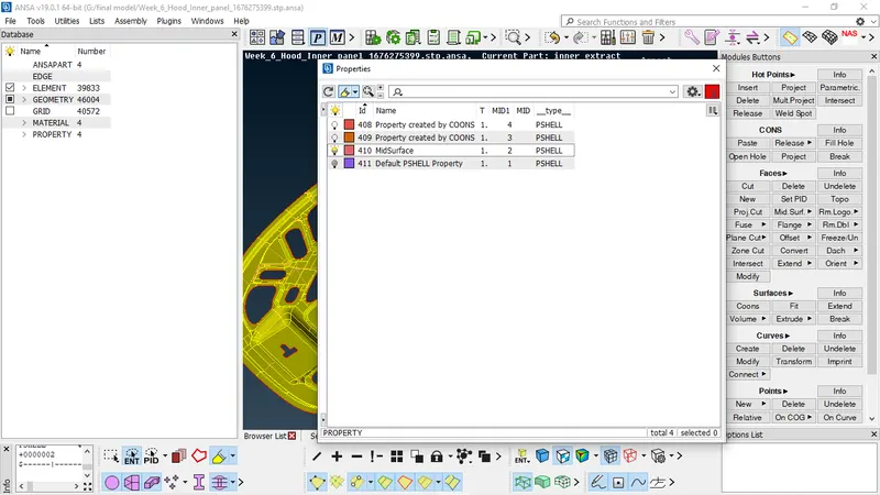
QUALITY CRITERIA SETUP AND MESH GENERATION-
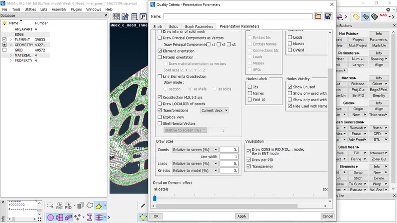
In this we need to put the following quality parameters and Mesh Parameters first i put the mesh parameters given in the question.
- Target Length = 5
- Min Length = 2
- Max Length = 7
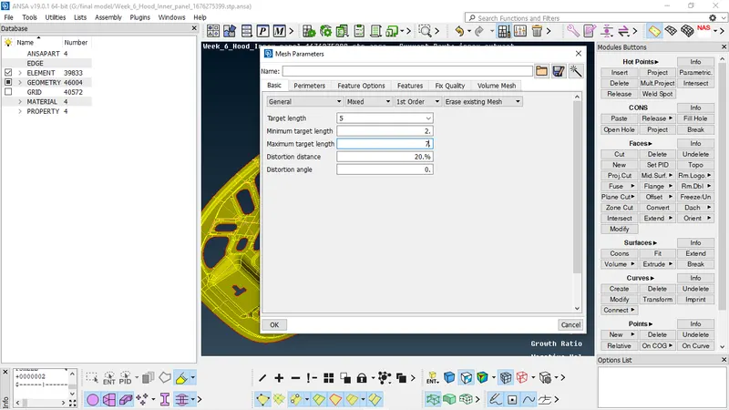
After mesh parameter we go for quality criteria, quality criteria has to be define as per the requirement, the requirement for this model is given in question are a follows.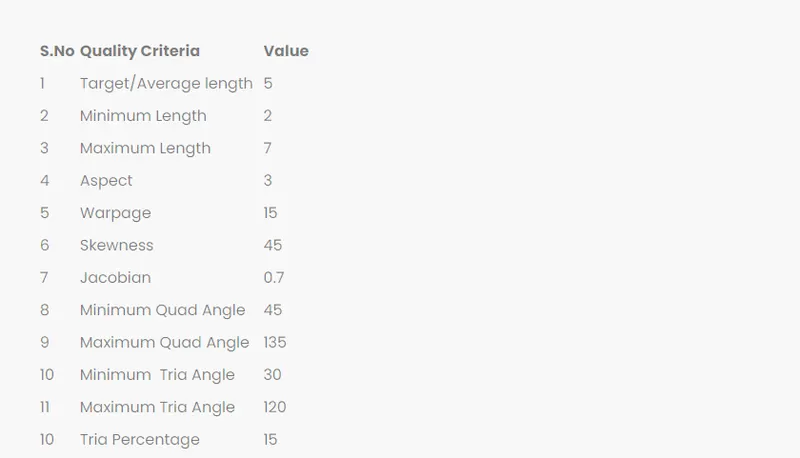
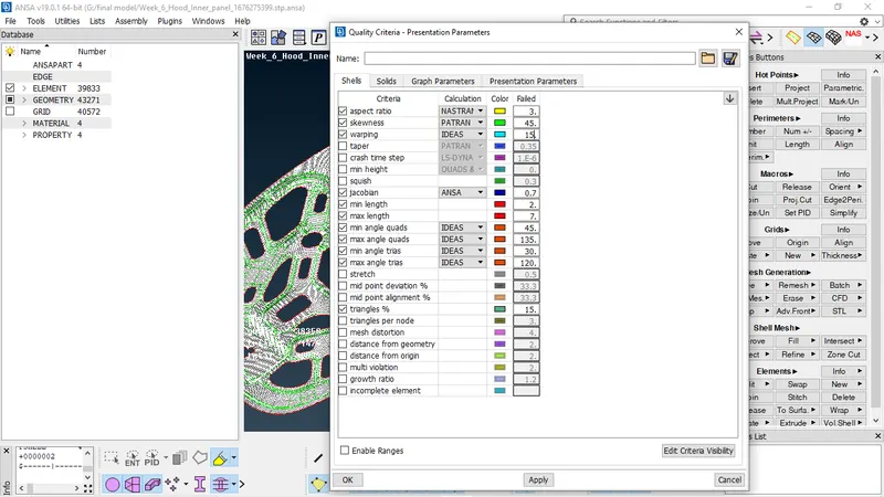
MESH GENERATION AND QUALITY IMPROVEMENT
In this i used the BEST MESH option for generating the mesh its basically the process of discretizing Model into small numers of element its like NET type of structure. we just need to select the face after clicking on the BEST mesh and pressing the middle mouse button to generate mesh.
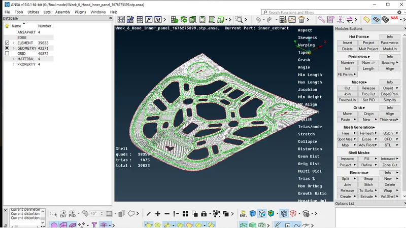
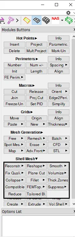
After this process many elements will fail for the given quality criteria so we need to improve quality for good mesh flow, for that we have many commands like Reconstruct, smooth, split, improve, join etc all these can be used for quality improvement, it will emiminate the maximun no of errors present in the model.
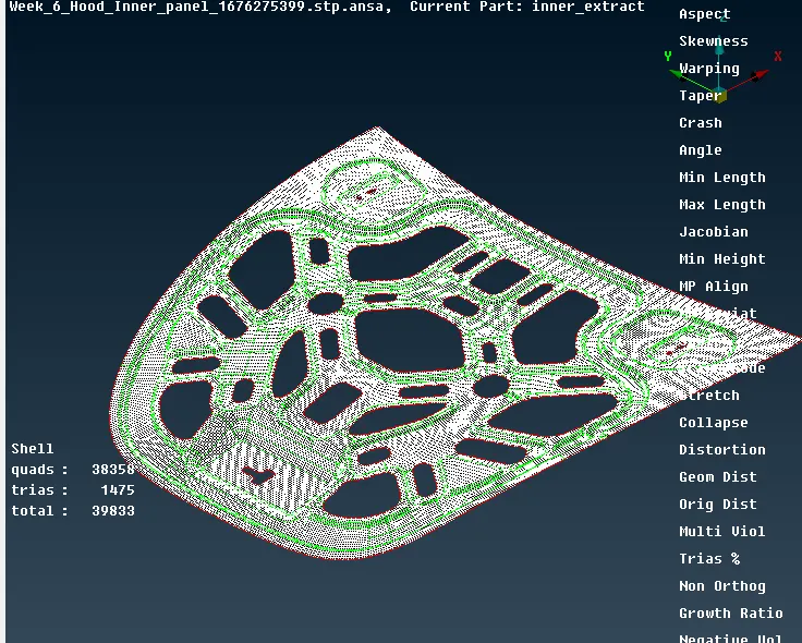
FINAL MODEL IMAGE
RESULT-
After Working on this model i got to know various commands of Ansa like BOOLEAN, TOPO, RECONSTRUCT, SMOOTH, INSERT,OFFSET, PID, MATERIAL, JOIN etc. and its user Interface, during this project i got to understand following things like how to solve geometrical errors, how to identify cons, types of cons, and quality & mesh parameters importance and its improvement.