Project 2 - 2D meshing on the instrumental Panel
OBJECTIVES- To extract the mid surface and mesh the given Instrumental panel using the given quality criteria and assign correct thickness to the property.
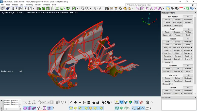
CAD MODEL IMAGE-
PROCEDURE -
First import the CAD Model of Instrumental Panel into ANSA Software or interface, then perform an initial Topo/Geometry checkup, in this procedure we need to check for the following Geometrical errors present in the model like crack, overlap face, needle face, triple con, unchecked faces etc.
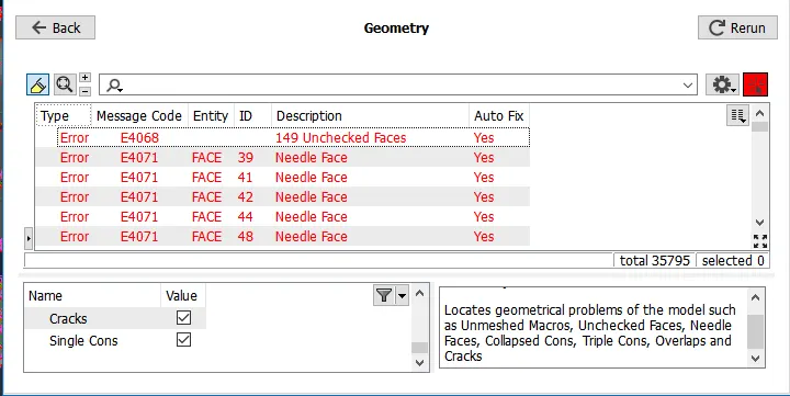
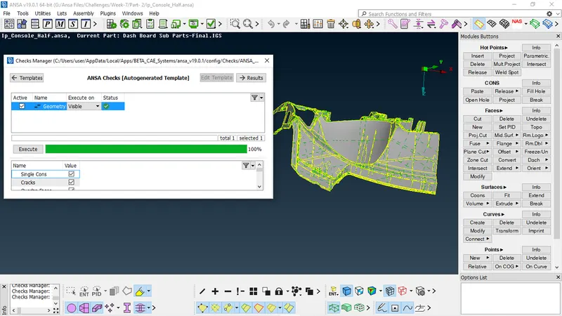
After the checkup fixing the errors if any, we can achieve this either by Manually or Autofix, hence all the CAD models were check for clean geometry and all their surface imperfections are fixed in the geometry check. after this procedure, geometry is free from error as we can see in below image.
Then Orient command is used to check the orientation is proper in all the faces of the CAD geometry.
MIDSURFACE GENERATION-
Before extracting the Mid surface of the components, its important to measure their thickness. And this can be achieved by using the command Measure. And by chosing the end of two hotpoints we can get the thickness of the geometry. so we can create Midusrface for each different surface manually.
As we know that there are different options are available to generate midsurface, soa as per requirement we can use any option to create midsurface.
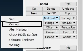
As this component is very small and complex, casting method suits best for plastic part as it will give us the middle mesh within a minutes, so for this project i use casting method to generate middle mesh as this model have Ribs, Doghouse, Fillets so this method will give us bad results in these regions and for that we wolud use Align manager.
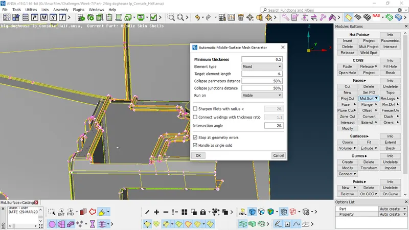
Before using Casting Method we need to set quality parameters, and mesh attributes. the quality parameter and mesh attributes, for the mesh is defined using the command Quality Criteria ( by clicking F11 ).
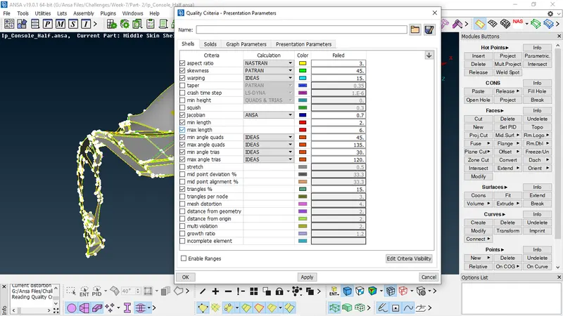
Then switch to Presentation parameters tab, In Graphics division put tick mark for Elements% and choose the Details on demand effect as 'More details'.
Then Click on the Mesh parameters and give the following values mention below
- Target Length = 4
- Min Length = 2
- Max Length = 6
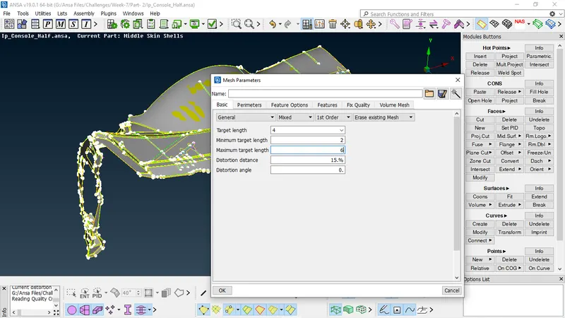
After puting all the values now click on the Perimeters - Length command and choose the entire component and give the target length of the mesh value as 4. (Given in question). The same should be also done for the Macro.
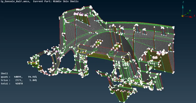
hence after that middle mesh is generated using casting method. we can se some of images of middle mesh below.
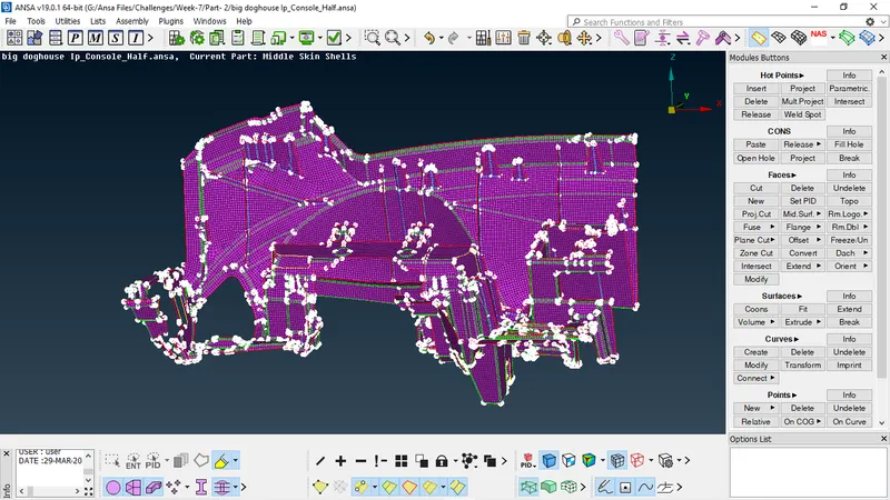
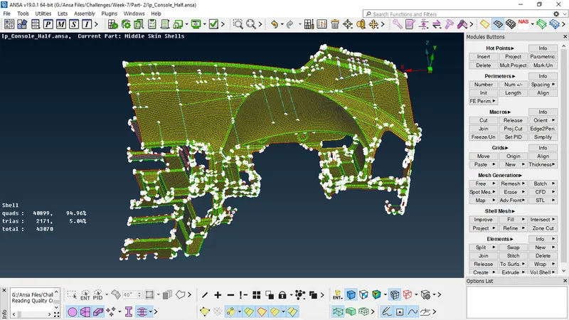
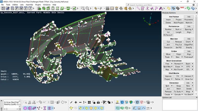
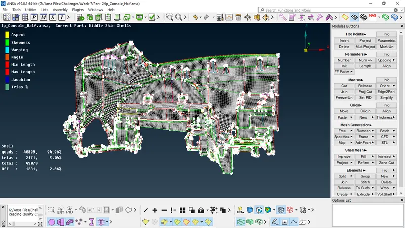
We can see that middle mesh is generated through Casting method, but it didnt capture proper mesh near some regions Doghouse, Ribs, Fillet, so for that i used Align Manager tool to get good result in that region.
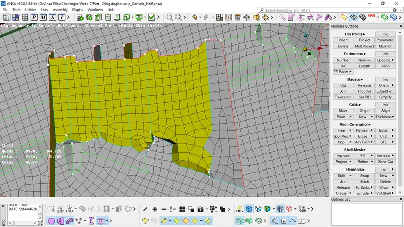
Damaged dog houses by casting operation
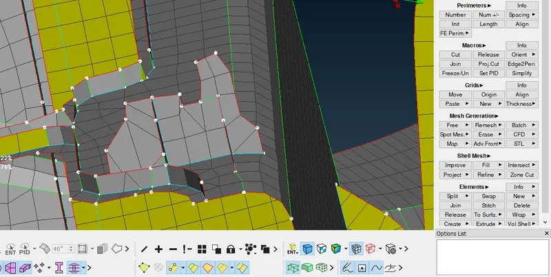
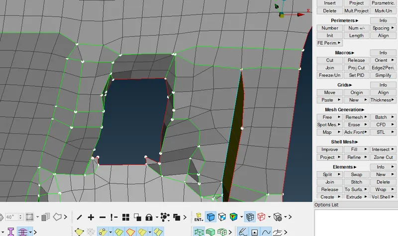
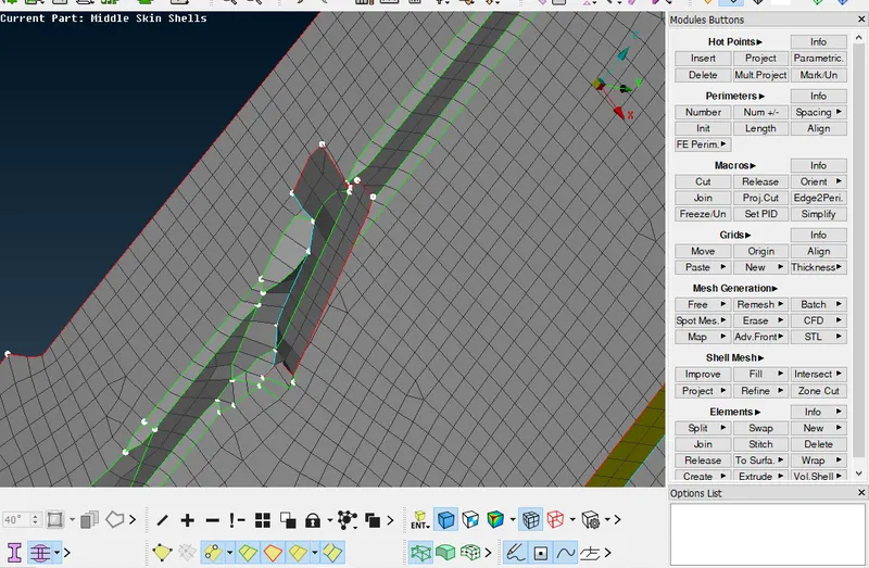
As this model has a lot of ribs which are reinforcement structures needed to maintain rigidity. They can be captured using a number of methods available in the ANSA.
DOGHOUSE
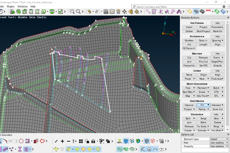
As all the doghouse contain ribs and are hollow from inside so they were captured in the form of a cross as shown in the attached figure. in above image i used Curve -> Create method to get a curve and after that using Shell mesh -> Fill to create a middle mesh. hence middle mesh is generated for Doghouse.
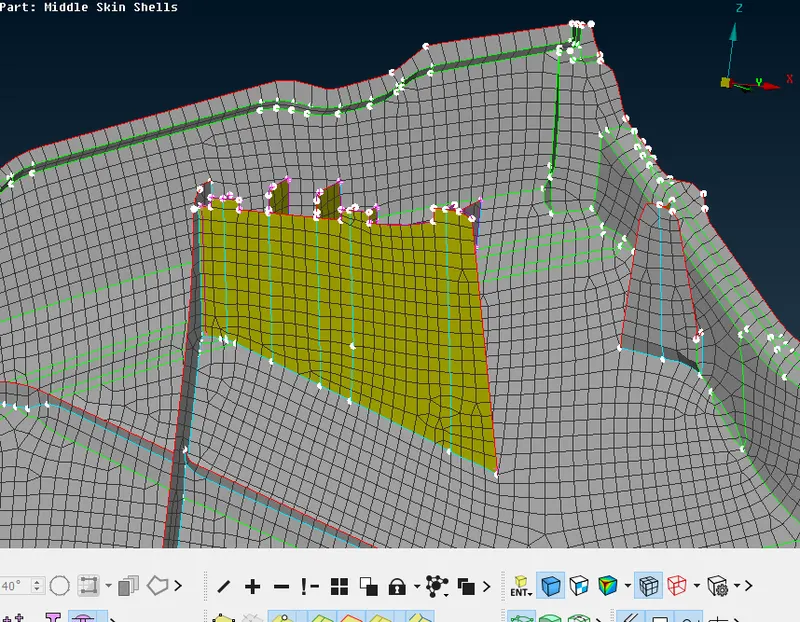
Here we have another Doghouse for this i used Align manager-> Faces and assign its perimeter definition. after properly assigning the perimeter definition doghouse is ready similarly i used Align manager -> Faces for all the doghouses present in the model and after making correction we can see the results in below images.
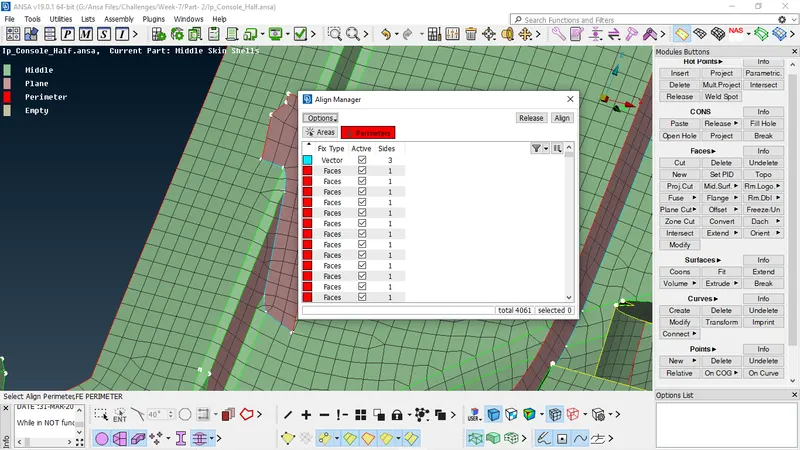
Select the perimeter of doghouse-> Area will be highlighted in the dialouge box of align manager right click on the highlighted section -> select -> New -> Perimeter , now select the two side of faces in which highlihted are lies, assigning is done.
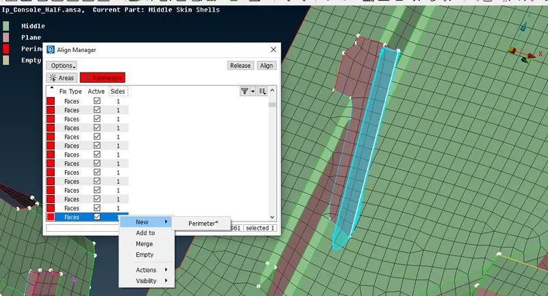
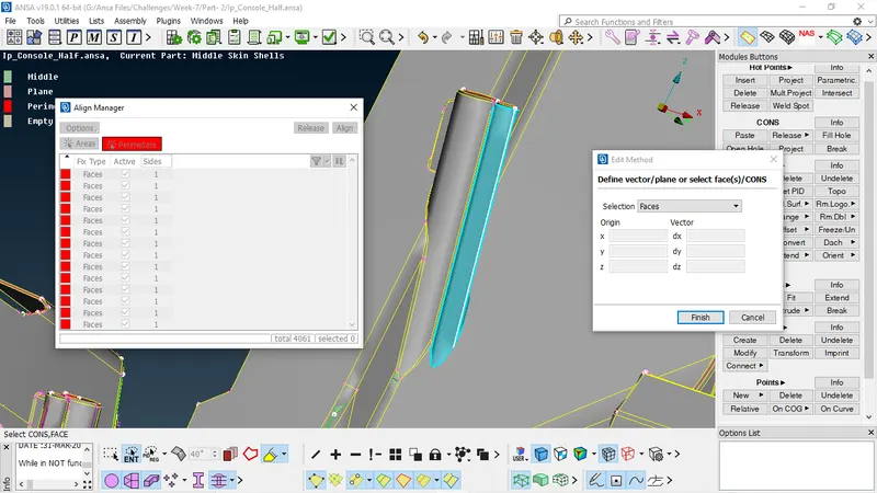
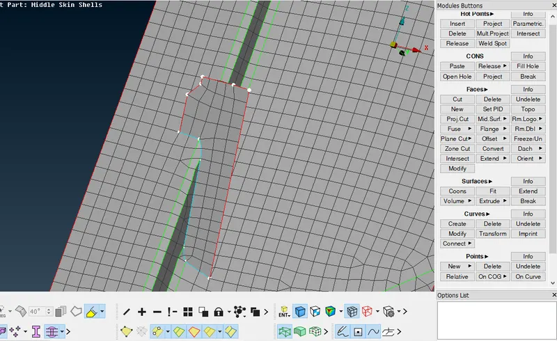
Similarly all the doghouse must be capture in the same manner, using Align Manager.
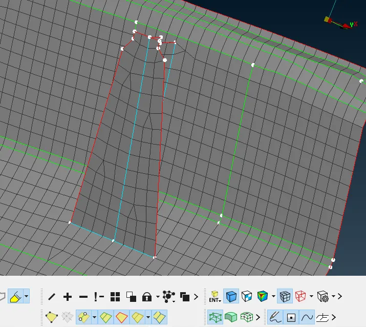
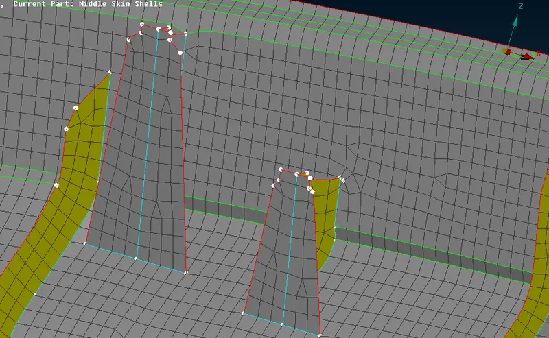
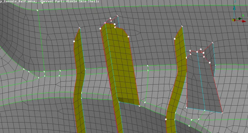
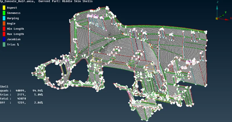
The image shows the middle mesh of the whole part after making correction near complicated areas using Align manager.
QUALITY IMPROVEMENT-
After Casting, we can see in above image, that there are some OFF elements near triple cons and trias formed on the free edges, so we need to improve the quality for good mesh flow, for that Quality check is performed on the generated mesh. Mesh is adjusted in such a way that it follows the required quality criteria.
OFF Elements, these elements are manually tried to be fixed using functions like MESH -> Shell Mesh -> Reconstruct and Smooth .
The trias formed on the free edges and feature lines are removed using MESH -> Elements -> Split function. So by using these commands we can eleminate Trias from our model and hence the condition can also be achieved.
Failures that cannot be cleared using above mentioned functions, are tried using Grids -> Move function. this function displaces the grid on the same surface in any direction as cursor movement.
CONCLUSION-
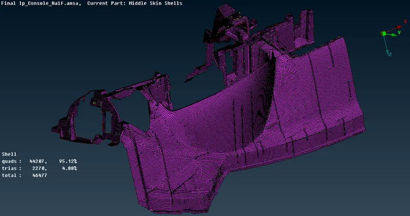
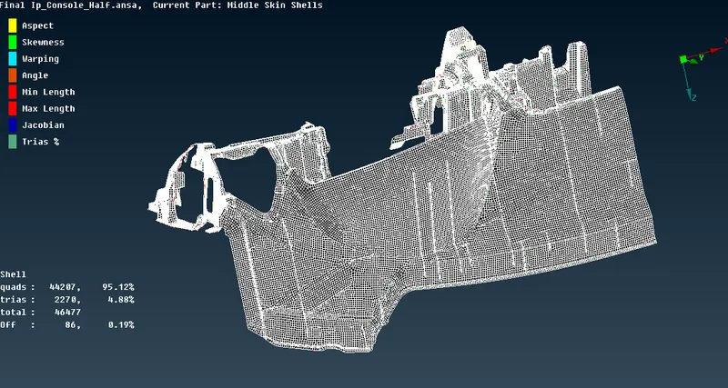
- Align Manager and some other operations were performend, hot points were added removed as required to obtain the uniform mesh as much as possible.
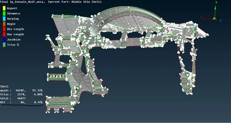
- The quality failures are reduced from 1232 to 86, The off elements could not be removed completely due to the close-lying triple cons sharp edges and single cons.
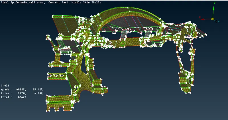
- The triangle percentage is 4.8 % which is well below the permissible limit.
- The thickness is enabled for mid-surface FE by enabling Draw Shell as Solid in Quality Criteria -> Presentation Parameters.
LEARNING OUTCOME-
- Casting is a great tool for Generating middle mesh of Large and complicated geometry. It automatically gives us the middle surface within fraction few minutes. paste, move options can be used to improve the quality of mesh.
- Using align manager to rectify the issues in mid-FE got from Casting.
- Achieved the mesh on given IP console using casting and align manager method. Reduced the time by using the casting method.