Week 4 - 2D Meshing for Sheet Metal
OBJECTIVE - To Perform CAD model Check for the given CCB Model and implement Meshing according to the required Quality criteria.
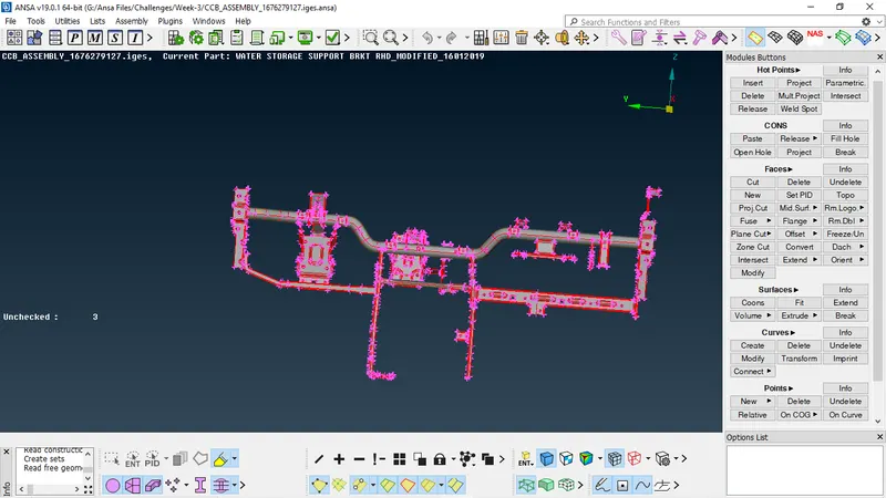
CAD MODEL IMAGE -
PROCEDURE -
GEOMETRY CLEANUP -
First import the CAD Model of CCB Assembly into ANSA Software or interface, then perform an initial Geometry checkup in this procedure we need to check for the following Geometrical errors present in the model like crack, overlap face, needle face, triple con, unchecked faces etc. After the checkup fixing the errors if any, we can achieve this either by Manually or Autofix.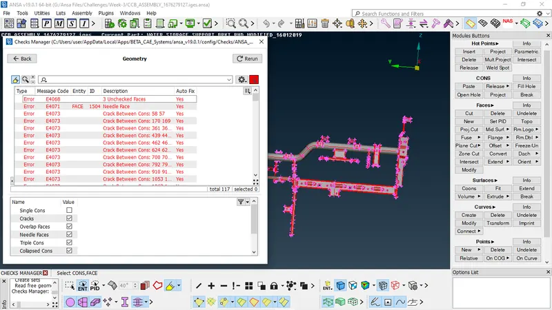
MIDSURFACE GENERATION -
For this Project Midsurface has to be achieved manually, as the thickness for each component varies so i used offset Command, midsurface is generated, each component has a seperate PID and component having same thickness assign in a same PID, also we need to put the value of Thickness (T).after that topology is performed in each component individually.
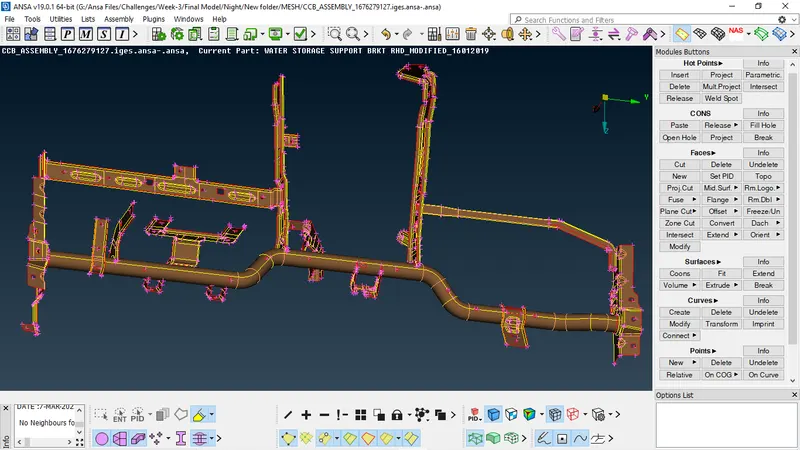
After Generating Midsurfacing another geometry checkup is conducted.
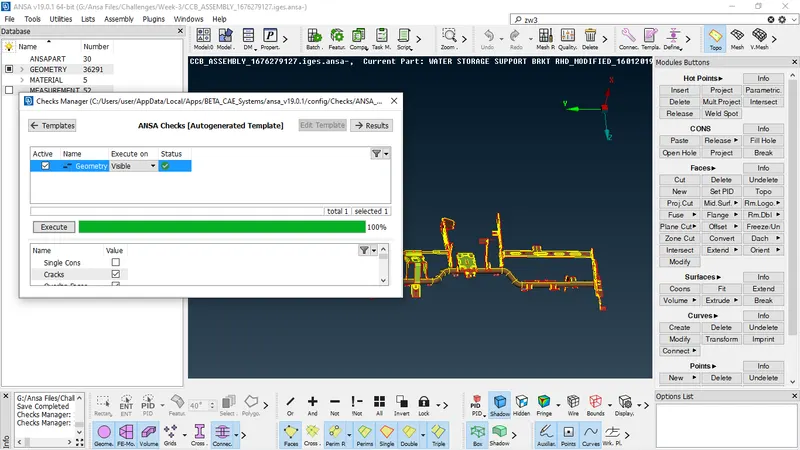
PID SETUP FOR MIDSURFACE-
In this we need to assigned the quality parameter and mesh attributes, the parameter given for the Mesh attributes were are as follows.
- Target Length = 5
- Min Length = 3
- Max Length = 7
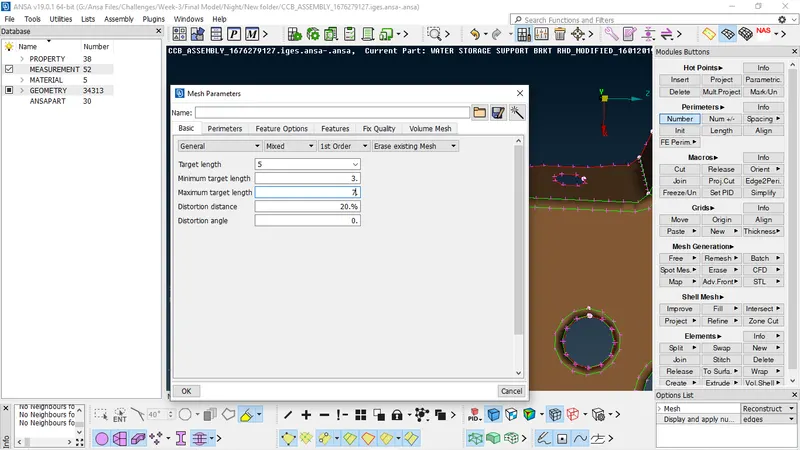
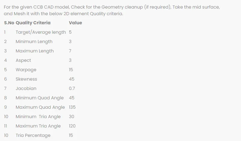
After mesh criteria quality parameter are assigned, as per the requirement, the requirement for this model is given in question are a follows.
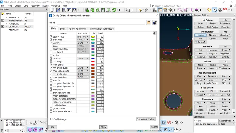
MESH GENERATION AND QUALITY IMPROVEMENT-
BEST command is used to Generate Mesh (its basically the process of discretizing Model into small numbers of element), in this we just need to select the face after clicking on the BEST Mesh command and pressing the middle mouse button to Generate mesh.
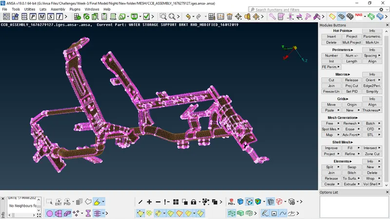
After this process many elements will fail for the given quality criteria so we need to improve the quality for good mesh flow, for that Quality check is performed on the generated mesh. Mesh is adjusted in such a way that it follows the required quality criteria.
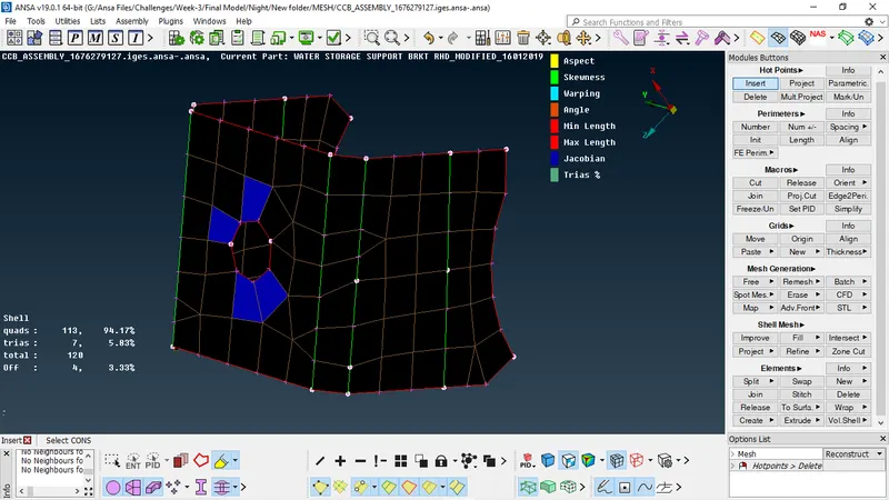
Bad Mesh Flow with some trias and error
To obtain Good Mesh flow Mesh cleanup is done so that quality of mesh improve, it can be achieved by using combination of following commands such as.
- Reconstruct
- Swap
- Split
- Improve
- Smooth
- Join
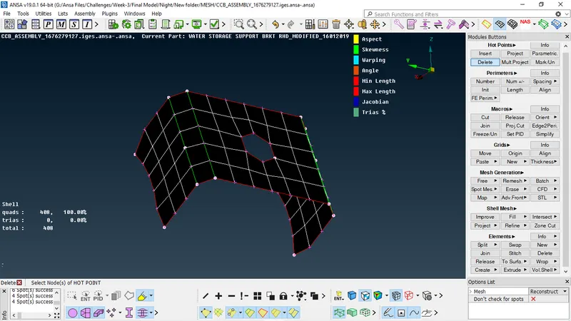
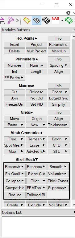
All these commands can be used for quality improvement, it will emiminate the maximun no of errors present in the model.
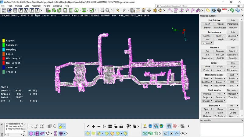
After successful meshing, thickness is assigned. In the presentation parameters, "Draw shell as a solid" feature is switched on.
FINAL MODEL IMAGE
RESULTS-
As we can see that there are some errors present in the model at only one region this is because of distance between two nodes is very less (2.82mm), and as per our assigned quality criteria minimum length should be 3mm, so at that particular region shown below our model is failing in minimum length. which can be avoidable. if we will try to fix this then some other part might get effect.
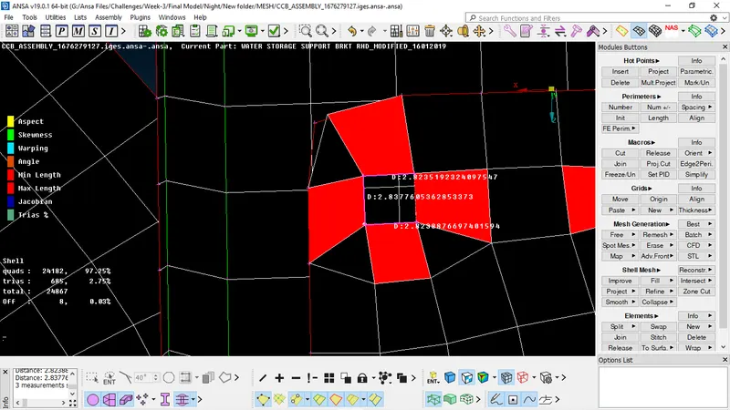
Cuts and join operations were performend, hot points were added removed as required to obtain the uniform mesh as much as possible. Final mesh obtained was error free except only one particular region, and satisfies all the required quality criteria given in the question. therefore the cad model of CCB Assembly is ready for further analysis.