Week 4 -To analyze the simulation of bending of wire for 3 different non-linear material and find required output in ANSYS
OBJECTIVE:- To analyze the simulation of bending of wire for 3 different non-linear material and find required output in ANSYS
CASE 1- Copper Alloy (Non-Linear)
PROCEDURE:-
- Open Ansys Workbench and choose static structural.
- In the Engineering data, let the material be structural steel and also choose Copper Alloy non-linear from General non-linear material with default values.
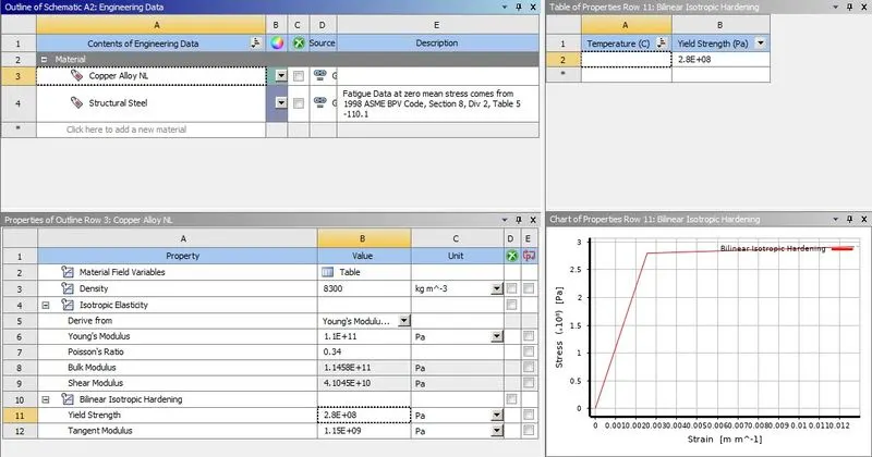
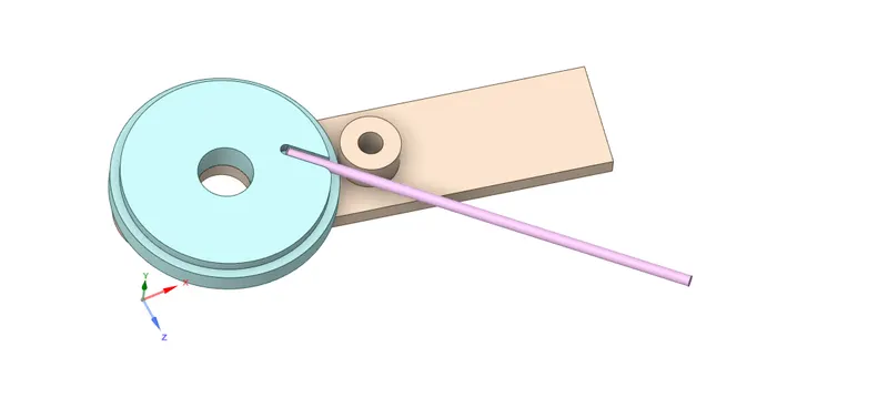
- For the geometry, right-click and import the given Wire bending model.x_t and open with space claim.
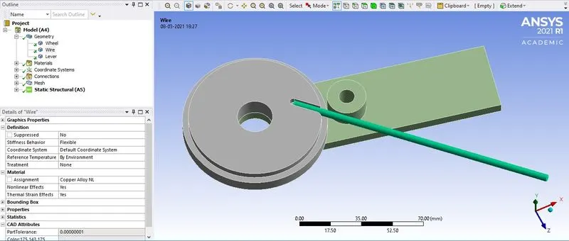
- Now in the workbench goto Model -> Edit, in the model window check the Geometry for the material and assign Structural Steel to the wheel and lever and Copper Alloy NL to the wire.
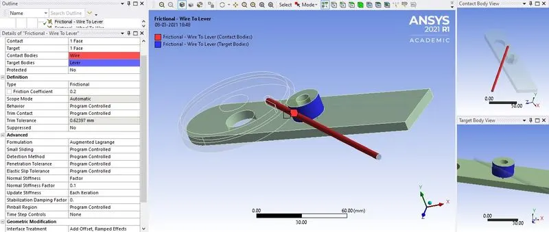
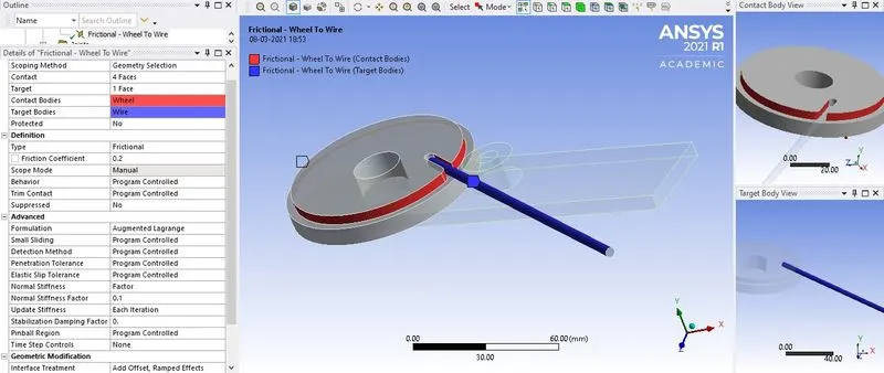
- For contacts, there are 2 types of frictional contact one Contact= wire to Target= lever and the second Contact= wheel to Target= wire, select the required faces and for both the contacts Type= Frictional and Friction coefficient= 0.2, Formulation= Augmented Lagrange, Normal Stiffness= Factor, Normal stiffness factor= 0.1, update stiffness= each iteration and Interface Treatment= Add Offset, Ramped Effects.
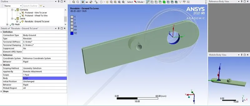
- As the lever need to rotate, a revolute joint is assigned to the hole of the lever by Connections -> Body to ground -> Revolute, click on Scope and choose the face of the hole of lever and also reference coordinate system need to be assigned as shown.
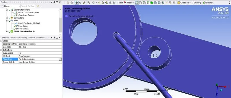
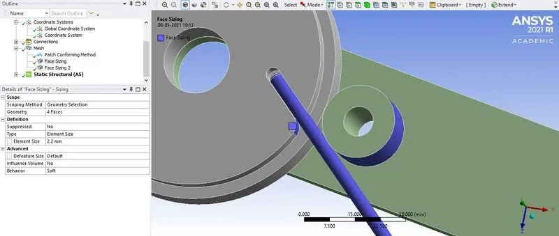
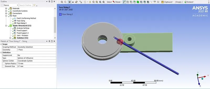
- For mesh, the 3 bodies will have a patch conforming method with tetrahedron elements and face sizing is applied to the recommended faces for an element size of 2.2 mm.
- To refine the mesh further on the area of interest a cartesian coordinate system need to be created by selecting the face of the edge of the wheel where the wire interacts and offset the coordinate to X= 3mm and Z= -3mm.
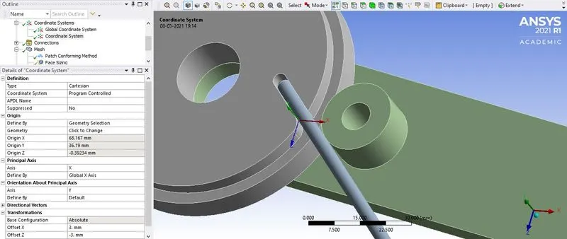
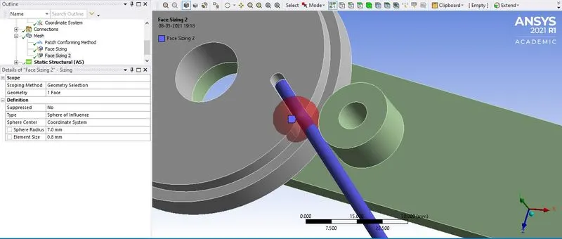
- After creating the coordinate system in mesh select sizing and choose the wire face, Type= Sphere of influence, Sphere Center= Coordinate system, Sphere radius= 7mm and element size= 0.8 mm. Before generating mesh set the mesh quality= low and click on generate mesh.
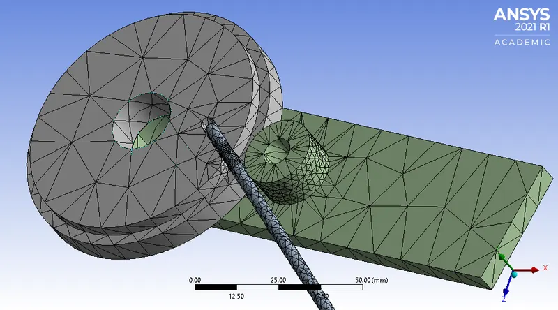
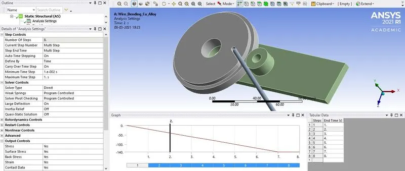
- For the analysis setting, the total number of steps will be 8 out of which for the first step Auto time stepping= on, define by= time, initial time step= 0.1s, minimum time step= 0.001s, maximum time step= 0.2s, Solver type= direct, Weak spring= program-controlled, Large Deflection= on, under Output control switch everything to yes.
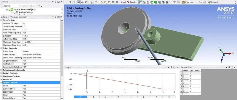
- Select step from 2 to 8, Auto Time Stepping= On, Define by= time, Carry over time step= on, Minimum time step= 0.01s and Maximum time step= 1s
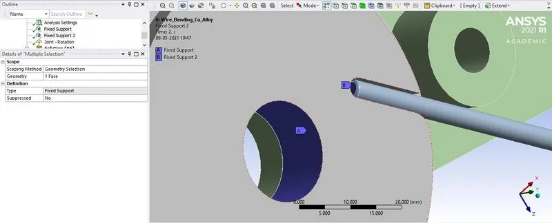
- Apply fixed support to the wheel centre face and the face of the wire.
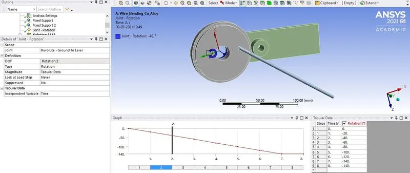
- Apply joint rotation to the lever, Joint= Revolute- ground to lever, type= rotation, Magnitude= Tabular data as shown.
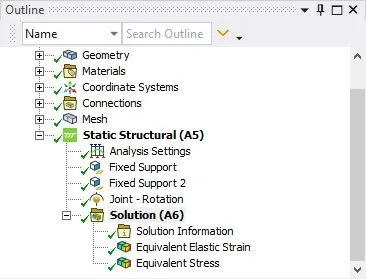
- In the solution request for the required output like Equivalent stress and Equivalent strain on the wire alone. Click on solve to generate the result.
CASE 2- Aluminium Alloy (Non-Linear)
PROCEDURE:-
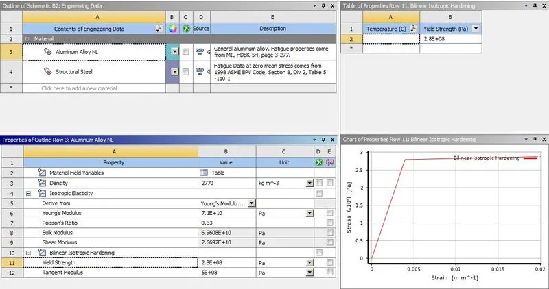
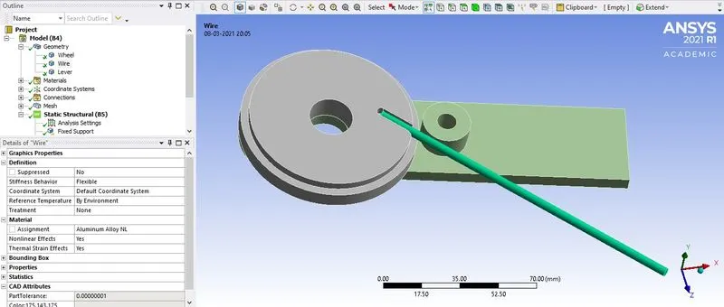
- All of the procedure used to set up the analysis will be similar except the material will be Aluminium Alloy Non-linear which is assigned to the wire in the model edit.
CASE 3- Magnesium Alloy (Non-Linear)
PROCEDURE:-
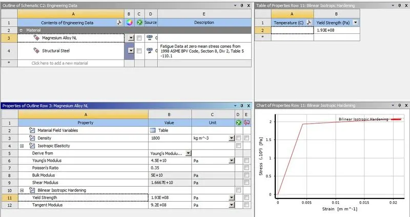
- All of the procedure used to set up the analysis will be similar except the material will be Magnesium Alloy Non-linear which is assigned to the wire in the model edit.
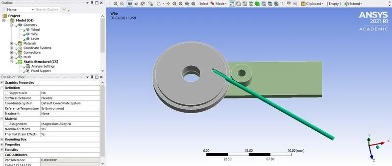
- Apart from that for the wire with magnesium alloy change the face sizing of the wheel edge element size to 0.7 mm.
RESULT:-
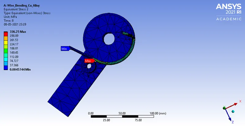
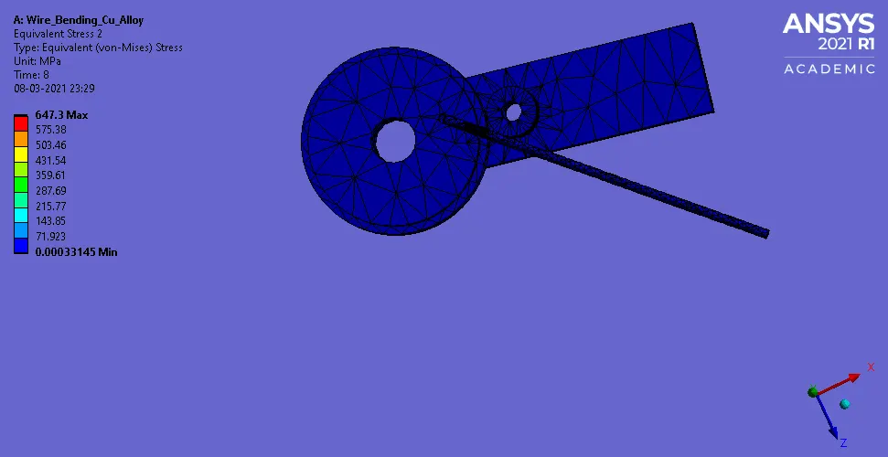
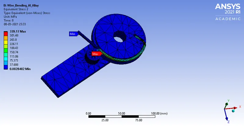
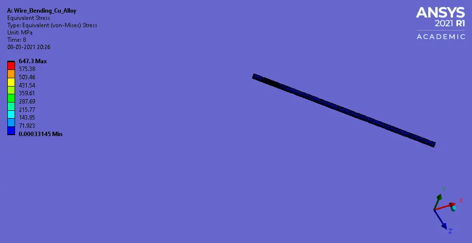
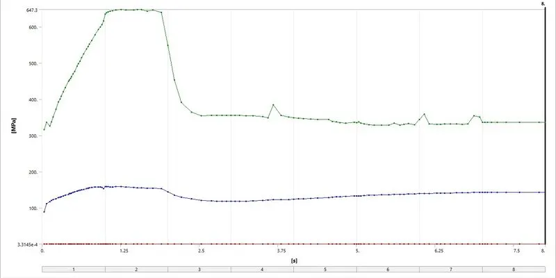
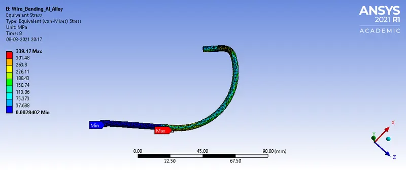
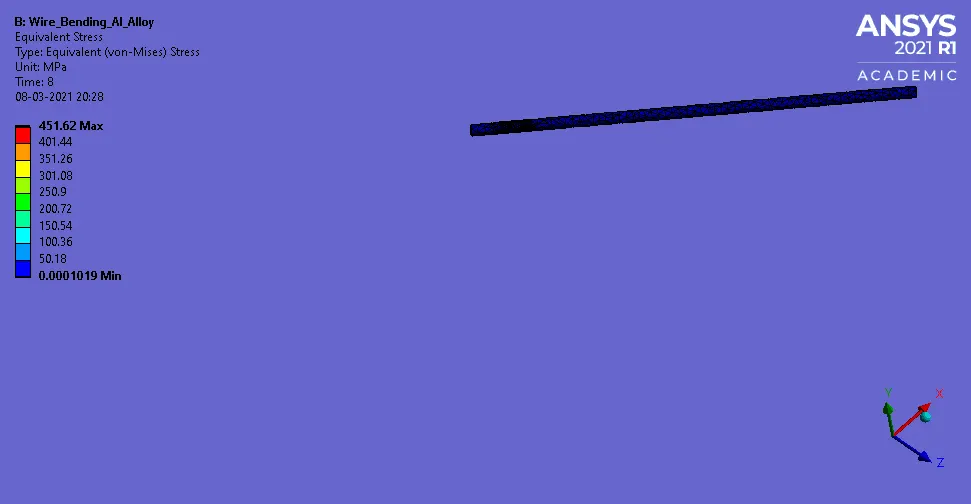
Equivalent Stress
CASE 1- Copper Alloy (Non-Linear)
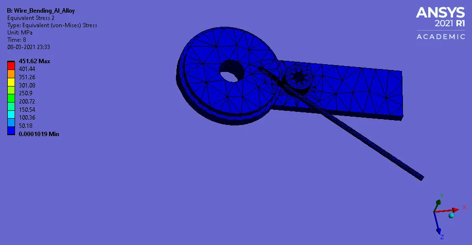
CASE 2- Aluminium Alloy (Non-Linear)
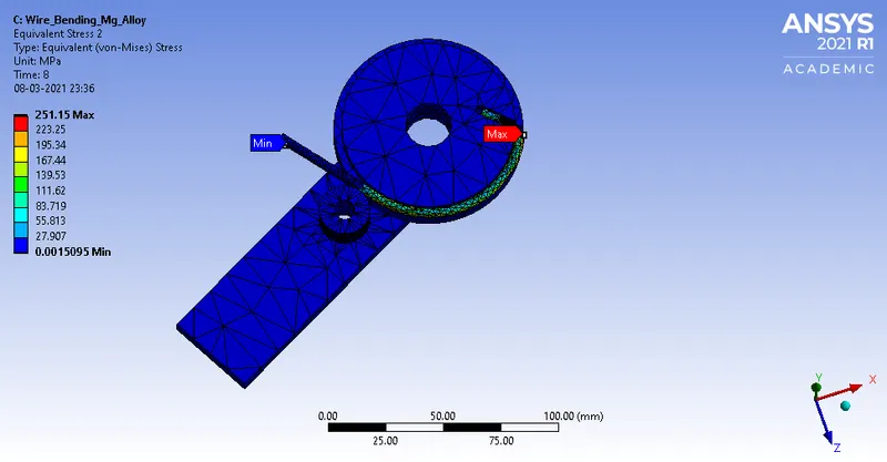
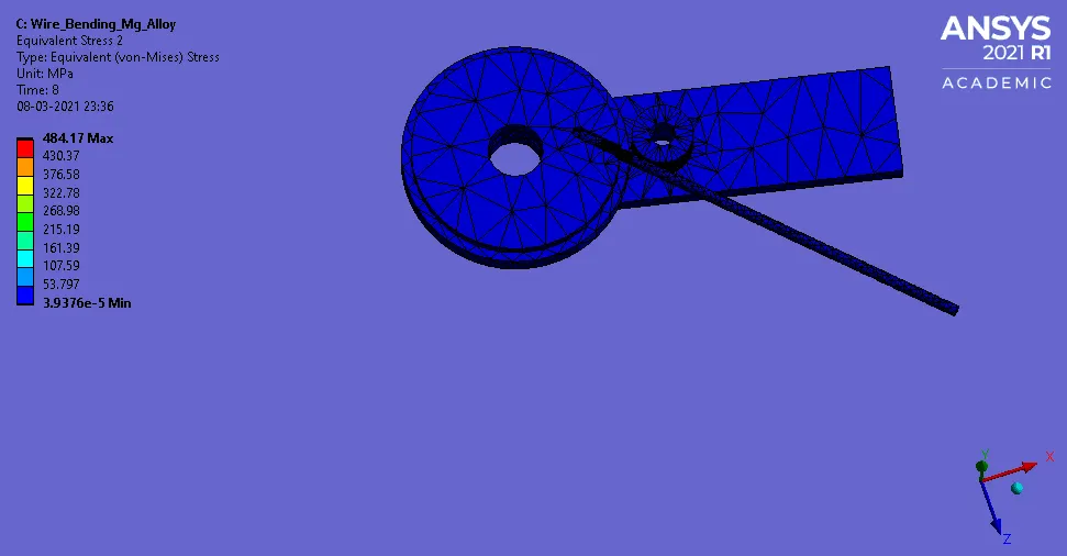
CASE 3- Magnesium Alloy (Non-Linear)
Equivalent stress on the wire
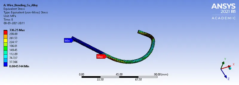
CASE 1- Copper Alloy (Non-Linear)
CASE 2- Aluminium Alloy (Non-Linear)
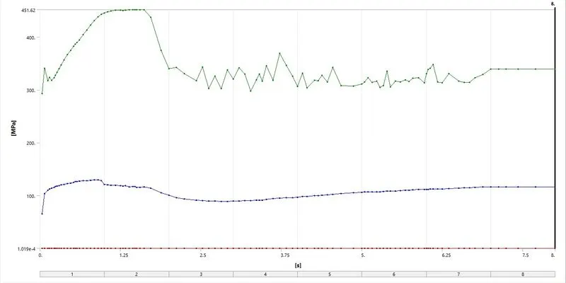
CASE 3- Magnesium Alloy (Non-Linear)
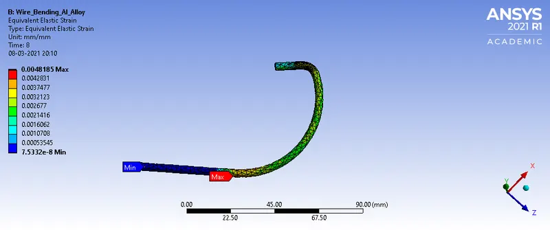
Equivalent Elastic strain on the wire
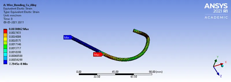
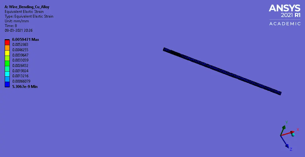
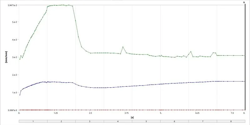
CASE 1- Copper Alloy (Non-Linear)
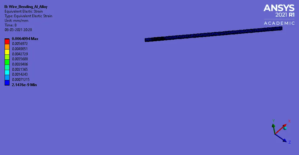
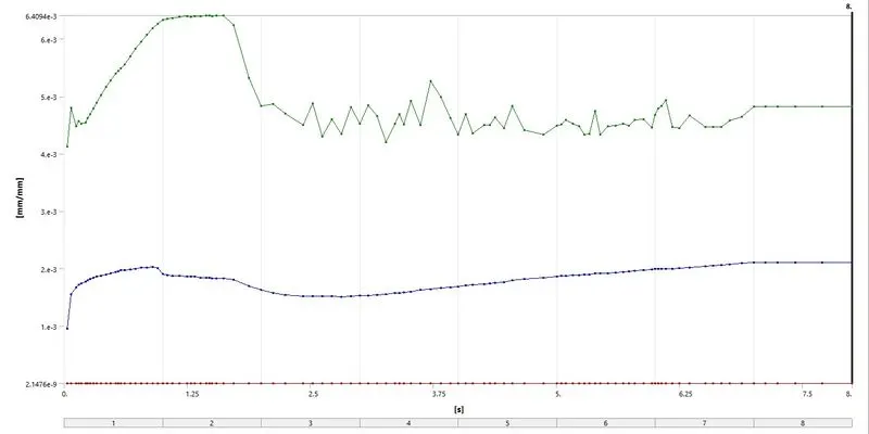
CASE 2- Aluminium Alloy (Non-Linear)
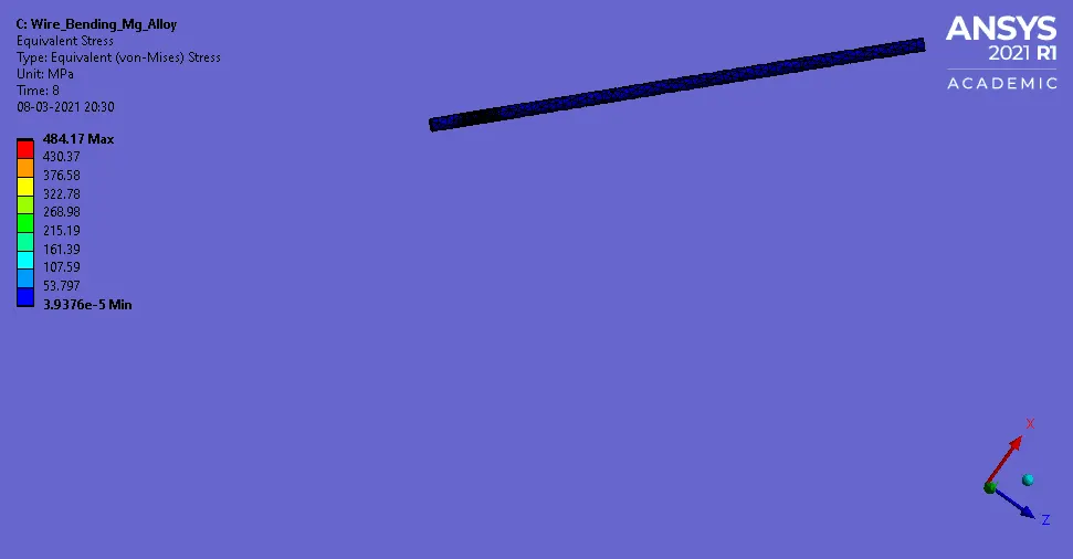
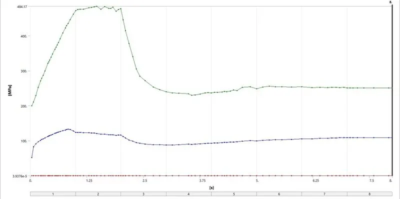
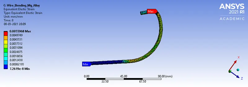
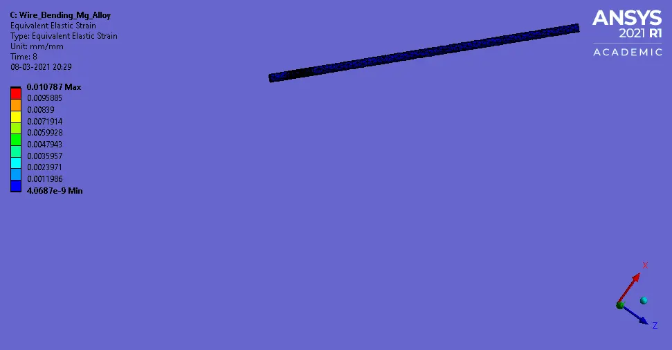
CASE 3- Magnesium Alloy (Non-Linear)
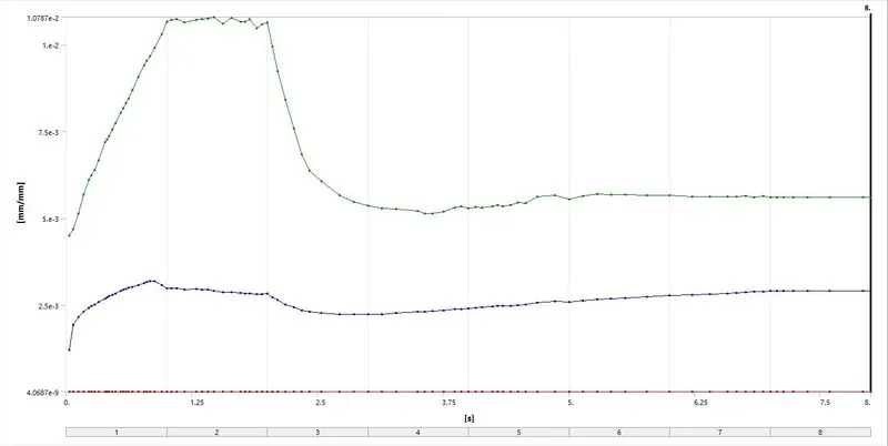
COMPARISON:-
| Equivalent stress on the wire | Equivalent Elastic Strain on the wire | |||||
| Minimum (MPa) | Maximum (MPa) | Average (MPa) | Minimum mm/mm | Maximum mm/mm | Average mm/mm | |
| Copper Alloy (Non-Linear) | 4.5744e-003 | 336.25 | 143.15 | 7.7945e-008 | 3.0862e-003 | 1.6243e-003 |
| Aluminium Alloy (Non-Linear) | 2.8402e-003 | 339.17 | 116.43 | 7.5332e-008 | 4.8185e-003 | 2.1076e-003 |
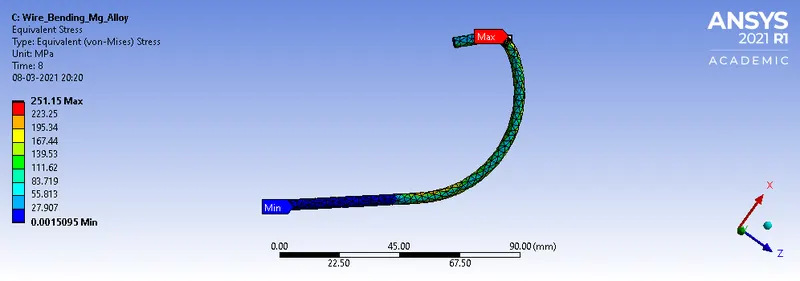
| Magnesium Alloy (Non-Linear) | 1.5095e-003 | 251.15 | 108.82 | 7.2619e-008 | 5.5968e-003 | 2.8937e-003 |
- It can be observed from the analysis and the table data that the wire made of magnesium alloy non-linear experiences the least maximum stress of about 251.15 MPa while the wire made of aluminium alloy non-linear experiences the highest maximum stress of about 339.17 Mpa also the highest maximum strain experienced is by the magnesium alloy non-linear wire while the lowest maximum strain experienced is by the copper alloy non-linear.
- In the material property, it can be observed that copper and aluminium have young's modulus 1.1E+11 Pa and 7.1E+10 Pa respectively which is higher than that of magnesium alloy non-linear which have young's modulus of 4.5E+10 Pa, as the young's modulus is the ratio of stress to strain, so it can be said strain is inversely proportional to young's modulus which justifies that magnesium alloy non-linear having lowest young's modulus have the highest strain of all about 5.5968e-003 mm/mm.
- As stress is independent of the material property young's modulus but the yield strength, which is the stress at which material begins to deform, of copper aluminium alloy non-linear is the same which is about 2.8E+08 Pa which is greater than magnesium alloy non-linear yield strength of about 1.93E+08 Pa, this justifies magnesium alloy non-linear having lower stress in comparison to the Copper and Aluminium alloy non-linear.
CONCLUSION:-
So from the analysis, it can be inferred that magnesium alloy non-linear experiences the lowest maximum stress in comparison to the Copper and Aluminium alloy non-linear while the maximum strain experienced is highest in the magnesium alloy non-linear in comparison to the Copper and Aluminium alloy non-linear.
Simulation:- "https://drive.google.com/file/d/1rBGi88EKcQmCAcB6MYRzCGR-fMukcziY/view?usp=sharing"