Week 4- Rolling operation
Objective:
To simulate the rolling operation on a workpiece made of copper. The problem statement gives us the model of roller and workpiece setup, the challenge is to perform structyural analysis for the same. The problem needs u to find the stresses in the entire setup, the strain in the workiece and the deformation in the workpiece in the direction perpandicular to direction of translational motion.Ultimately, the problem wants us to prive that the workpiece hs moved by 900 mm.
Rolling operation:
Rolling Process is a deformation process in which Metal(s) in its semi-finished or finished form is passed between the two opposing rollers, which reduces the metal’s thickness through the compression process. The rollers rolls around the metal as it squeezes in between them. The Rolling Process consists of two opposing rollers and a metal squeezing in between them. The basic consideration is that the thickness between the rollers should be less than the Metal’s (Ingot) Initial Thickness.
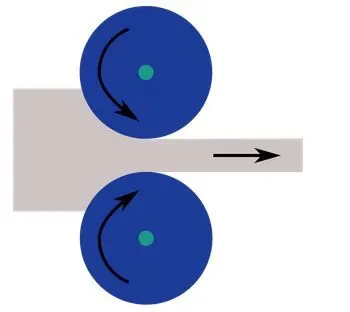
The Woking of Rolling might be clear from its basic definition. It is a Manufacturing Process consist of Rollers that are present at a distance from each Other. The Metal in its Semi-finished or finished form is squeezed through the Rollers gap, sliding at the ends.
Rolling Process has three stages of Completion viz. primary rolling, hot rolling and cold rolling.
Analysis of metal rolling
Step 1: Geometry Creation
The geometry was imported from the model of bending assembly provided.
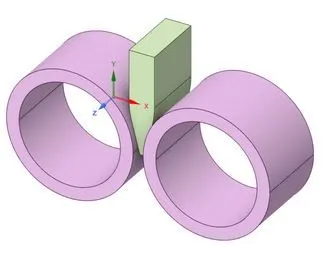
It was requested that the length of the workpiece be increased by 60 mm and it's width be dereased by 8 mm on each side. Hence, the model was edited by importing it into spaceclaim, the length of the workpiece was increased by 60mm and its width decreased on both sides by 8mm.
Step 2: Material Selection
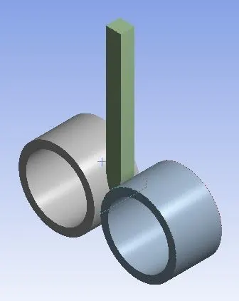
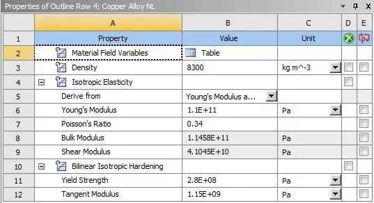
The material for worpiece has been given as copper, we can add this material from general non-linear materials in engineering data. Both rollers are defined with structural steel as the material.
Step 3: Meshing
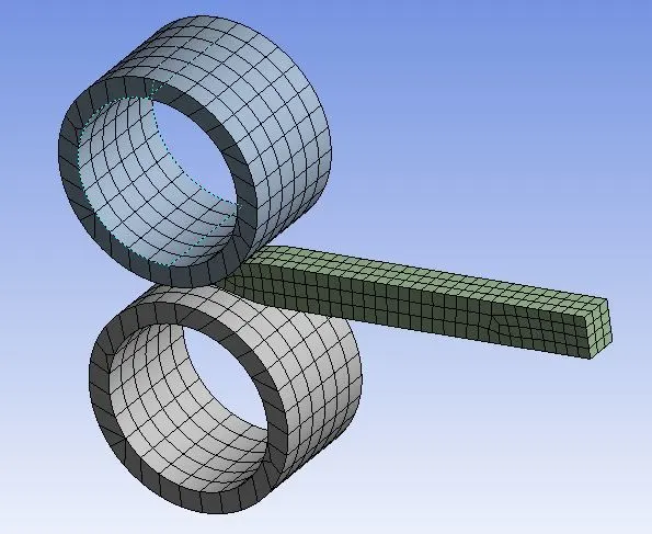
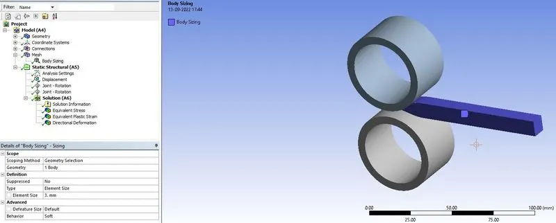
Meshing has been done in this analysis in stages. The workpiece is meshed with an element size of 3 mm, while rollers are given an automatic mesh.
Step 4: Processing
Processing the model involves creation of connections, Joints, Bouindary conditions, Loads etc.
1. Creation of Connections:
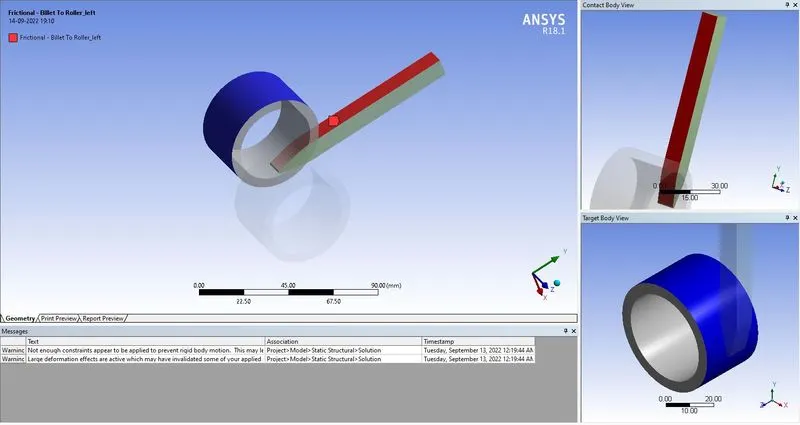
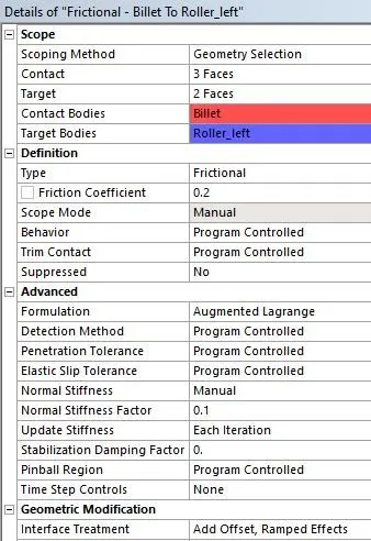
The contact between the two rollers and the workpiece is frictional and the coefficient of friction is taken as 0.2. The default contact is flipped and entire surfaces in contact is selected. The formaulation is updated to automated lagrange, and normal stiffness i updated to manual value where normal stiffness factor is taken as 0.1. The stiffness is updated for each iteration and interface treatment set to add offset, ramped effects.
2. Creation of Joints:
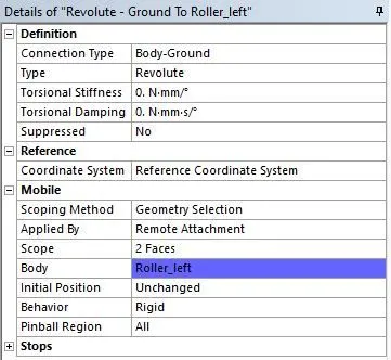
Two revolute joints are created with the rollers, the joints are body to ground joints and are created by selecting inner surface of the rollers.
2. Analysis settings:
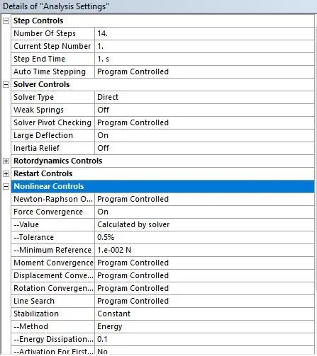
This solution is run in 14 steps considering the complexity of the analysis. We can observe the results in between the entire simulation at 14 individual points and study the changes in the sheet metal. Large deflection turned ON, non linear stabilization as constant, energy disipation as 0.1.
3. Application of loads:
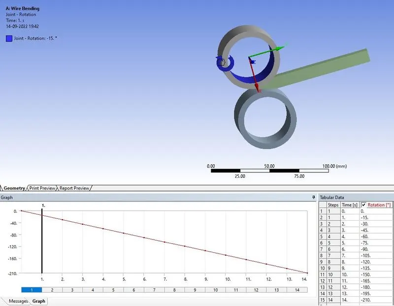
Since this simulation is performed to study the stresss in workpiece, instead of applying loads, a rotation is applied on the roller. The roller is rotated in steps of 15 deg. each. for each step of 14 steps.
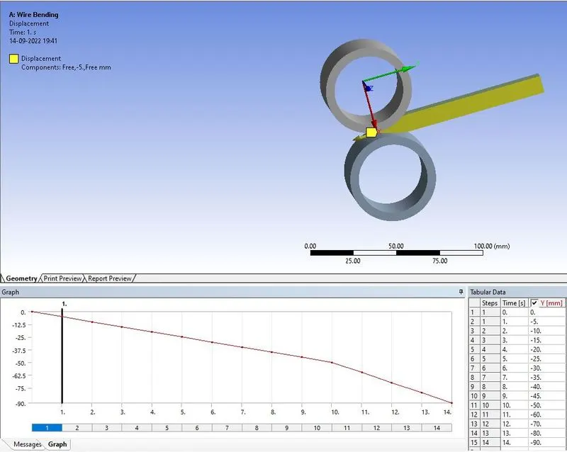
The worpiece was given displacment load and is displaced by 90 mm in 14 steps as shown above.
Step 5: Results and Post-Processing
The objective of the simulation was to find out the
- Equivalent stress for the whole setup
- Equivalent Plastic strain for the workpiece
- Directional Deformation in the Z axis for the workpiece
- Prove that the workpiece has displaced by 90mm.
1. Equivalent stress:
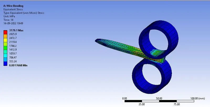
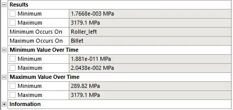
We can observe the stresses occuring on the workpiece as the max stress can be observed to be on the rolling area of the wrokpiece nd the area of the rollers in contact with the workpiece. The absolute max stress can be obsrved to be occuring on the part of the workpiece that is being compressed.
2. Equivalent plastic strain:
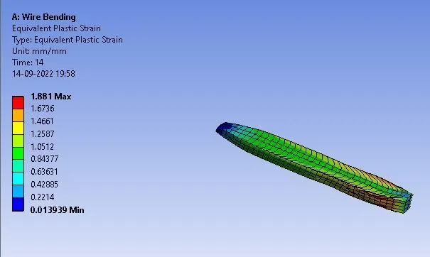
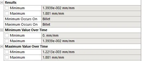
Max strain occurs at the location where rolling happens. It can be observed in the attached picture that max strain of 1.88 mm occurs at the location of rolling and min strain occurs at the location that is farthest from roling location.
3. Directional deformation in Z axis:
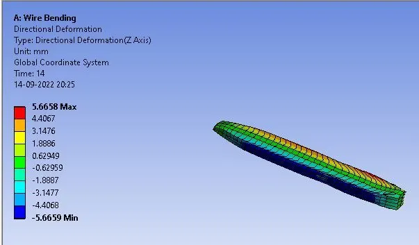
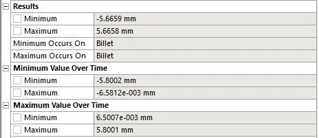
Max deformation in z axis is shown in the attached image. It can be observed that the max deformation occurs at the width of the workpiece. It can also be observed that the deformation in z axis is the same in both directions of the width of the workpiece.
4. Workpiece displacement:
To find out the displacement of the workiece, directional displacement in y-axis was performed. The free end of the workpiece was selected as the the surface to study displacement.
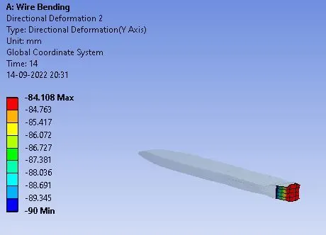
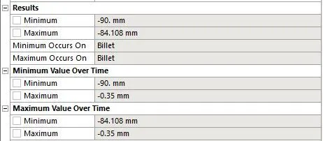
Max displacement of 90 mm is observed in the workpiece which can be considered as proof of displacement of workpiece.