Week 4:- Pin Unit Design Challenge
AIM: To design and understand the concept of Fixed Pin unit and Retractable Pin unit.
Components of a Pin Unit:
Pin:
- Pin is a part which locates the car panel.
- A pin can either be a make part or a standard part.
- Pin should have grinding surface on shaft with fits on to which the pin retainer will be fitted.
- The mounting surface of the pin should be a fine machined surface.
- The pin should have a step machine surface to lock the rotation, which matches with the pin retainer.
- The mounting surface of the pin retainer to the blocks should be a machined surface.
- Pin must have a fastening provision like tapped hole from the bottom or a V grove from the side.
Pin Retainer:
- Pin Retainer is a part which holds the pin in position, the pin retainer can either be a make part or a standard part.
- Pin retainer should have a hole with a fit, on to which the pin will be fixed.
- The pin mounting surface of the pin retainer should be a fine machined surface.
- The pin mounting surface of the pin retainer should have a step to lock the rotation of the pin.
- The pin retainer will be fixed to a block or a L block to the riser with 2 dowel holes(pins) and at least with one screw hole to maintain the tolerance.
Block/L Block:
These parts are mainly used to accommodate the shimming directions as per fundamental in general. Also in some cases these are used for other design feasibility.
Shims/Spacers:
Shims and spacers are some standard parts which are used for adjustments of locators (NC Blocks and Pin retainers) for obtaining the desired values for the precise working of a unit with respect to car part. In general, to adjust the Design to manufacturing deviation.
Blade:
Blade is part like a plate, which connects the parts of a unit to a riser. In general the blade can be either a make part or a standard part.
Riser:
Riser is a part on which all the parts of a unit are mounted, and it is mounted on the base plate of a tool. In general, the riser can either be make part or a standard part.
Dowel holes and machined surfaces:
All make parts which are to be assembled with tolerance should be designed with 2 dowel holes and at least of 1 to 6 threaded/free hole. And to be fine machined for the mounting surface with 3 to 5 mm step machining.
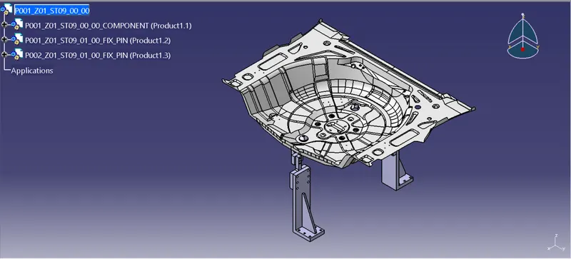
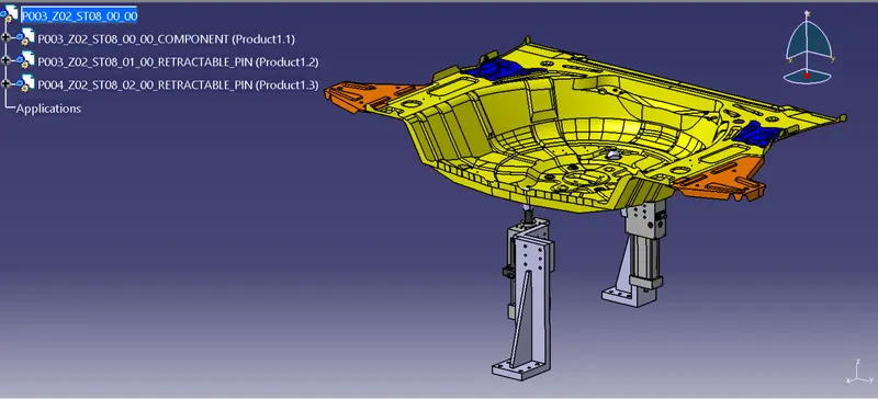
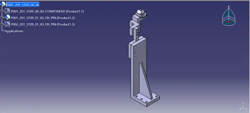
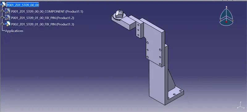
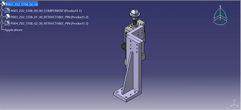
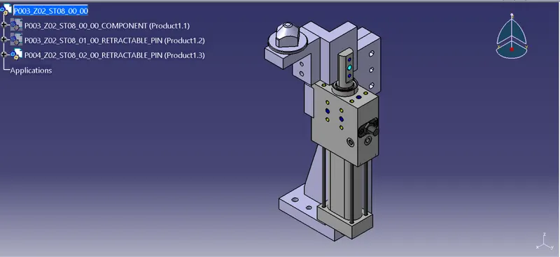
Process Followed to Design the Pin Units:
- Launch the CATIA V5 application and create new product file as (P00_Z00_ST00_00_00)
- Create another two product files into the main product file as (P00_Z00_ST00_00_00_COMPONENT) & (P00_Z00_ST00_00_00_FIX_PIN)
- Into the (P00_Z00_ST00_00_00_COMPONENT) file add the reference component
- And into the (P00_Z00_ST00_00_00_FIX_PIN) product file create multiple part files for pin, pin retainer, L block, blade, & riser
- Now select the pin part file and create a point at centre of pin hole location according to the component.Through this point create a plane.Use this plane to sketch the pin profile then use shaft command.
- Provide fillet at the edges of the pin.Create M10 hole at the bottom of pin to mount the pin & retainer together with bolt.
- For diamond pin sketch a diamond shape on top and use pocket
- Now select the pin retainer part file create plane and sketch the profile. Use pad and input the length. Using hole command create multiple holes for mounting of pin & L block
- Now double click on the block part file, select positioned sketch and sketch the block profile pad it then form mounting holes on the block surface
- Similarly select the blade file, sketch the desired profile, pad it input the length and also make the mounting holes
- For riser using the positioned sketch command, sketch the riser profile, pad it.
- Then also create the profile for rib and pad it. Make the mounting holes both threaded and not threaded
- To design the retractable pin unit first download the cylinder CAD data from www.tuenkers.com
- Create a product file as (P00_Z00_ST00_00_00_RETRACTABLE_PIN)
- Into this product file add multiple part files for pin, pin retainer, L block, blade, cylinder & riser
- This parts will be made in a similar way i.e. using sketch,pad,shaft & hole features
- For cylinder add the downloaded cylinder file directly and using move/snap commands place the cylinder in it's derired position