Week - 4 - crash box simulation
Objective:
To simulate a crash test for a crash box given.
Introduction:
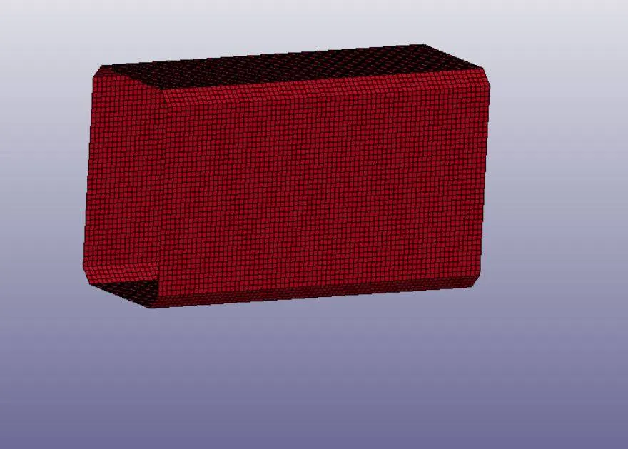
- Crash box is a thin-walled component which deforms axially and absorbs the energy during impact.
- The crash box is widely used in automobile and aerospace industry to absorb accidental impact energy.
- This safety component reduces the injuries by accidents and provides more safety to the passengers.
- Thekinetic energy is absorbed and reduced evenly by the crash box.
PROCEDURE:
The procedure is as follows,
- The given input fille is of .k file format, this file can be opened through LS-PrePost by selecting it as a keyword file.
- Unit system used for the analysis is gm-mm-ms.
- The given file does not consist of any rigid wall so a new rigid wall is created by using *RIGIDWALL_PLANAR card. This is done by selecting createentity>RigidWall>create option.
- The rigidwall type is selected as planar.
- N1-N2 method is selected which helps in selecting two nodes and normal for thegenerated rigidwall.
- The rigid wall is offset by 10mm from the crash box.
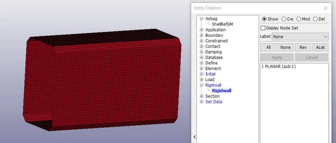
- The direction of the normal of the generated rigidwall and the velocity should be in the opposite direction.
- If the direction of normal of rigidwall and velocity of the crashbox is same then the crashbox penetrates through the rigidwall and problem statement fails.
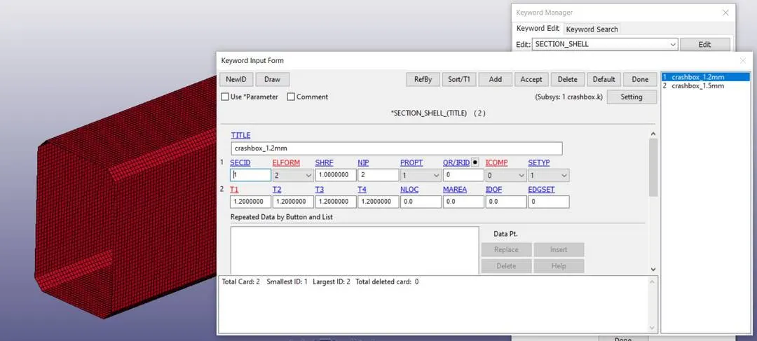
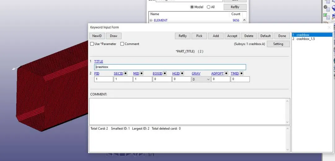
- Now, the section properties for the crash box are defined by using *SECTION_SHELL card. Only the shell thickness value of 1.2mm is entered keeping all other parameter values as default. One more card with new section ID is defined and the shell thickness 1.5mm is assigned to it.
- Define the material
Insert MAT properties as shown bellow,
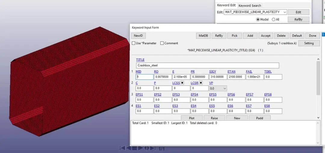
The above values are entered in mat_piecewise_linear_plasticity card.
- Now define velocity to the crash box by using create entity option.
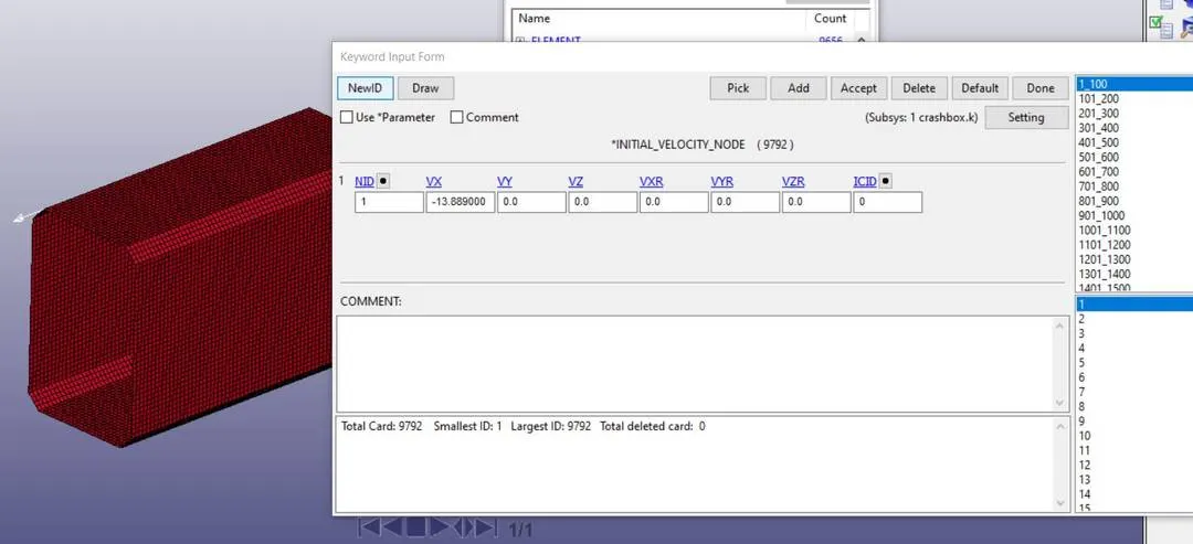
- The selection is done by part and the whole crash box geometry is assigned a velocity of 13.889mm/ms (50Kmph).
- This velocity is assigned to each node of the selected part that is carsh box here.
- The bellow fig shows the velocity assignment and the card generated after the initial velocity assignment card.
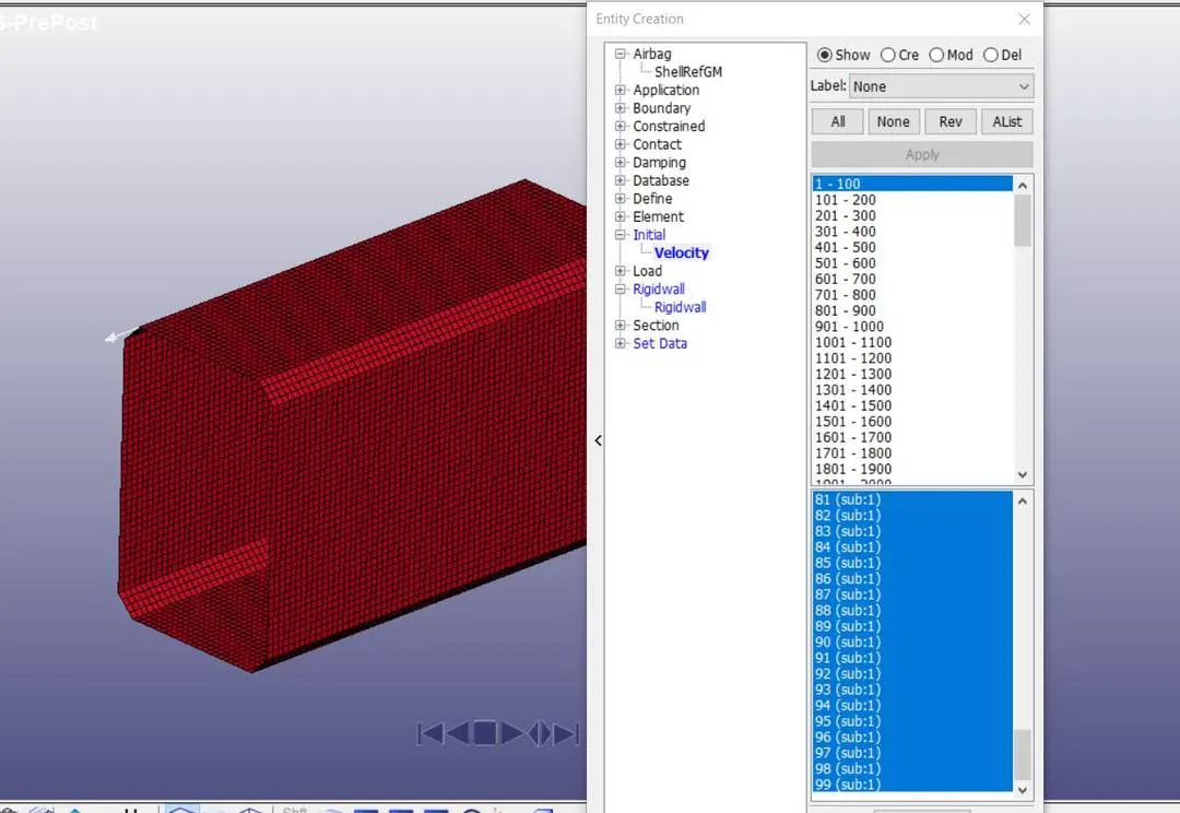
Also apply initial_vel_node card
Then assign section properties and material properties to crashbox ie part card.
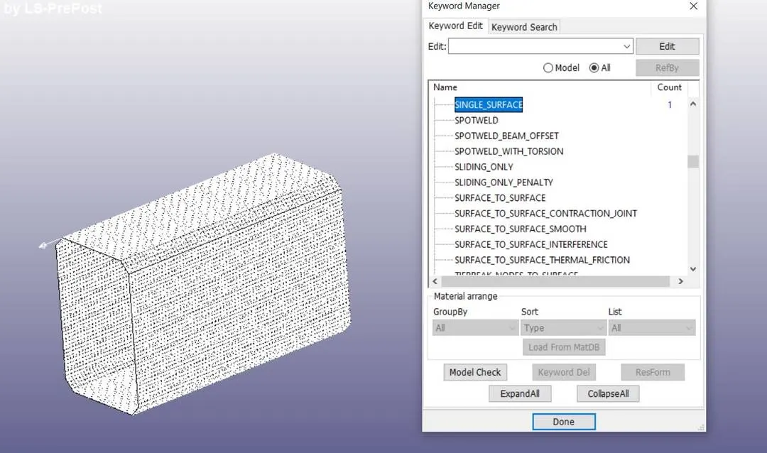
Define contact:
- In this case automatic single surface contact is used.
- Slave surface is mentioned in this case.
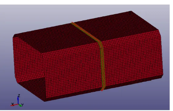
- To get the stress, strain, acceleration and energy values at nodes, sections and over the whole body. For generating section forces, creating specific node list and element list which defines the desired section is necessary.
- Mode list and element list can be created by 'create entity' option andselecting the required nodes and elements. The bellow fig shows the node and element selection. The selection of nodes and elements are done by pickingeach node and element through create entity>set data>*SET_NODE/*SET_SHELL toolbox.
- Termination time is assigned by using *CONTROL_TERMINATION card, *CONTROL_ENERGY is also used to calculate the energy dissipation.
- Hourglass energy,rigidwall energy, sliding interface energy can be calculated by this card assignment.
- The total time 1ms is assigned as end time in the *CONTROL_TERMINATION card.
RESULTS AND DISCUSSION:
By applying Binary_output card the simulation results can be achieved.
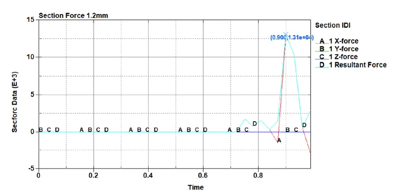
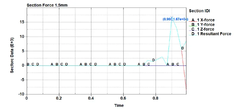
1) Cross sectional forces at the middle of crashbox.
2) For 1.5 mm thickness crashbox
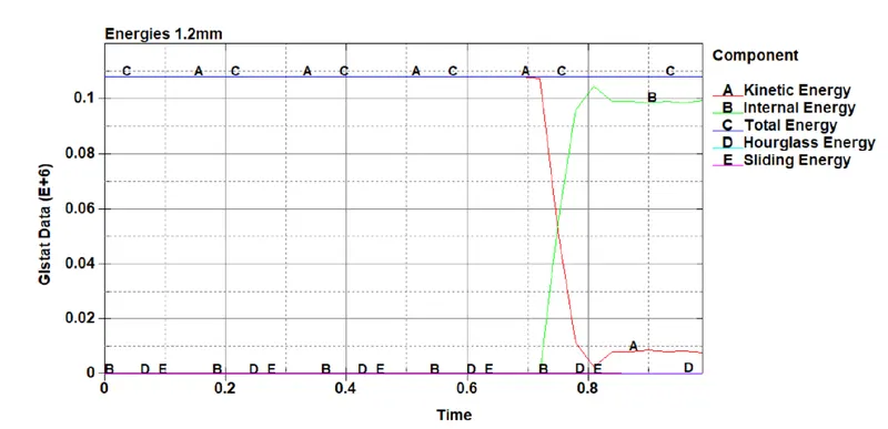
Energy Plots:
For 1.2 mm thickness crashbox
For 1.5 mm thk crashbox
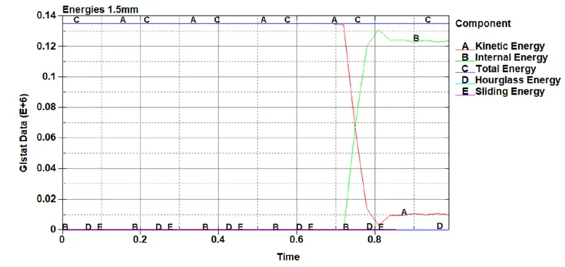
The above fig clearly indicates that 1.5 mm thickness crashbox absorbs more enrgy than 1.2 mm thk crashbox.
Acceleration plot for a node at middle of the section of crashbox:
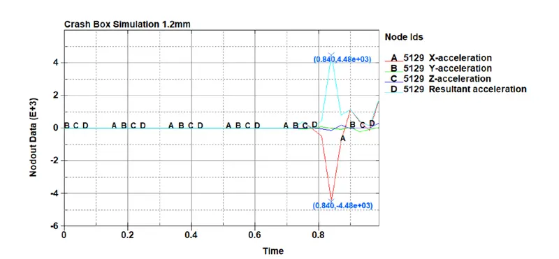
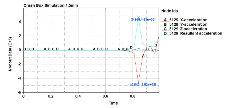
From above two graphs it is clearly seen that the accleration value in case of 1.5 mm thick crashbox is greater than that of 1.2 mm thickness crashbox.
Conclusion:
1) The above problem solving procedure helps to derive the assigned solution for the problem.
2) Section forces are important parameter in descrete FEA solving problems.
https://drive.google.com/file/d/1_Uqv7UiB6HtfHAZnSSoA0ACdm6Pts34M/view?usp=sharing