week-11 Joint creation and Demonstration
Aim: The joints of revolute, cylindrical, translational and spherical joints between two rigid bodies and two deformable bodies are compared in the Ls-dyna software.
Objective: The joints is part of the machine used to connect two or more parts together temporary or permanently. They will be designed in such a manner, there will be relative motion to these parts by Constraining the degree of freedom or let the constrain free depending on the mechanism.
Procedure:
(1) The revolute joint which is having the hinge joint will be used to in rotation motion. This type of motion is used in the door hinges and uniaxial rotation motion.
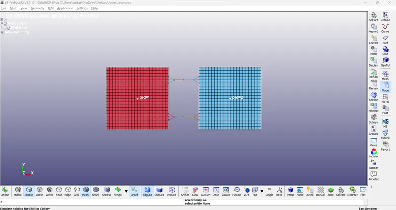
The meshed plates are imported with two parts.
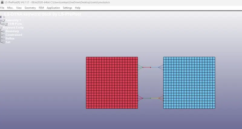
(2)The two bodies are considered to be rigid bodies with material properties card as MAT 20_Rigid.
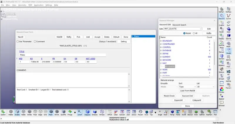
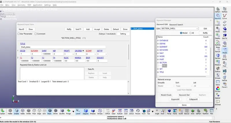
(3)The two parts assigned with the section and material ID.
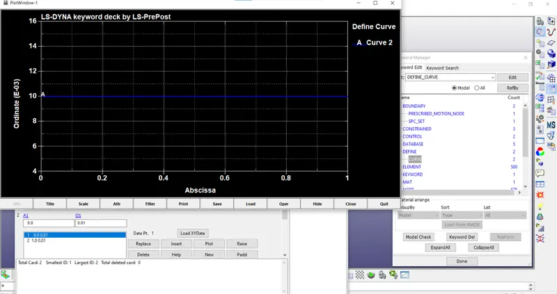
The Load curve is created using the define option.
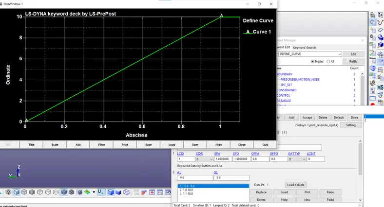
The time step is created using the define option.
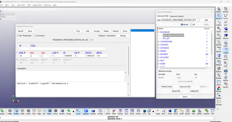
The boundary motion set is created with the displacement with LCID.
The four nodes are created with node ID.
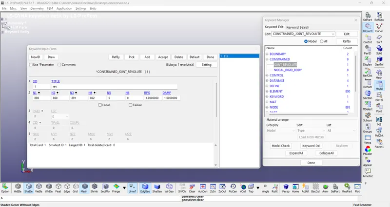
The revolute joint is made using the constraint option.
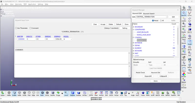
The termination card is used.
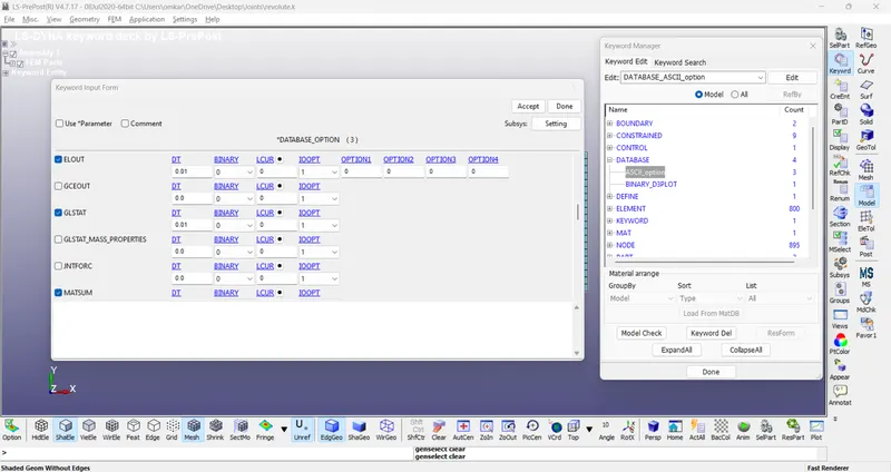
The ASCII option is set using the database.
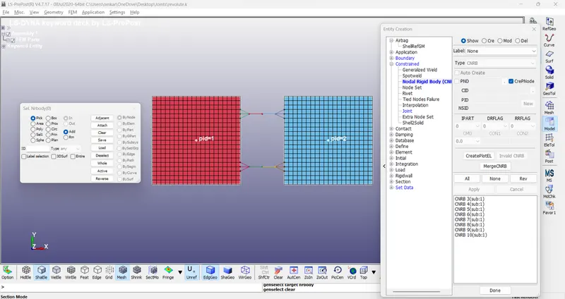
The Constrain Nodal rigid body (CNRB) is created by deleting the constrained extra node card.
The keyword File is saved and run.
Here, the two deformable bodies are considered by changing the material and replacing the constrain extra node with the Constrain Nodal rigid body (CNRB) and remaining cards would remain the same for the deformable revolute joint simulation.
The two bodies are considered to be rigid bodies with material properties card as MAT 24_piecewise Linear plasticity.
CASE 2 : CREATING THE CYLINDRICAL JOINT
All the Steps in this case are similar to the Case-1 except that steps 1,2 ,3 & 4. In place of those steps, the following steps are executed.
1. Creating two pairs of Co-Incident nodes forming the axis for the Cylindrical joints
Two pairs of Co-Incident nodes are created along the axis of the Concentric cylinders. Each node in a pair belong to two different cylinders.
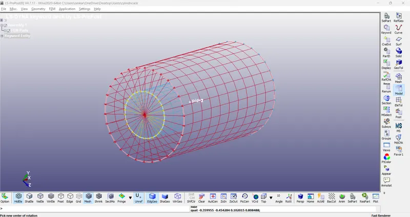
2. Creating the CNRB'S(Constrained Nodal Rigid Bodies)
Each different node of the Coincident pairs is used for creating CNRB with different Cylinder. Suppose, the nodes 679 and 680 are coincident then using the Node 679, the CNRB is constructed for the Cylinder-1 and using the node 680 the CNRB is constructed for the Cylinder-2. Hence, a total of four CNRB are constructed using the create entity tool bar. One of the coincident node becomes the parent node where as the other four nodes are chosen to be as the child nodes.
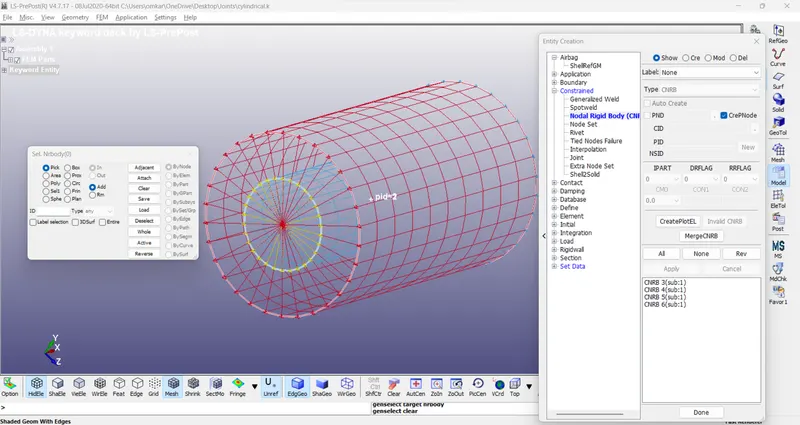
3. Creating the Cylindrical Joint
The Cylindrical joints are created by using the keyword *Constrained_Joint_Cylindrical. The Parent nodes of the CNRB are entered in the card in order to create the Cylindrical joint. N1 and N3 are the parent nodes connecting the Cylinder-1 where as the Nodes N2 and N4 are the parent nodes connecting the Cylinder-2.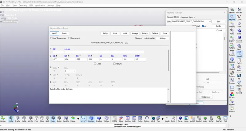
CASE 3 : CREATING THE SPHERICAL JOINT
All the steps in this case are similar to the Case-1 except 1,2,3 and 4. The following steps are to be executed in place of these steps
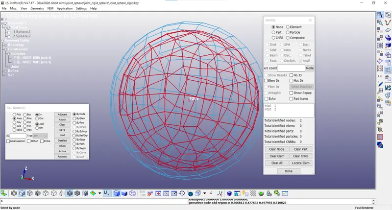
1. Creating a pair of Co-Incident Node
A pair of Co-Incident nodes is created exactly at center of the concentric Spheres. Each node belongs to different Sphere.
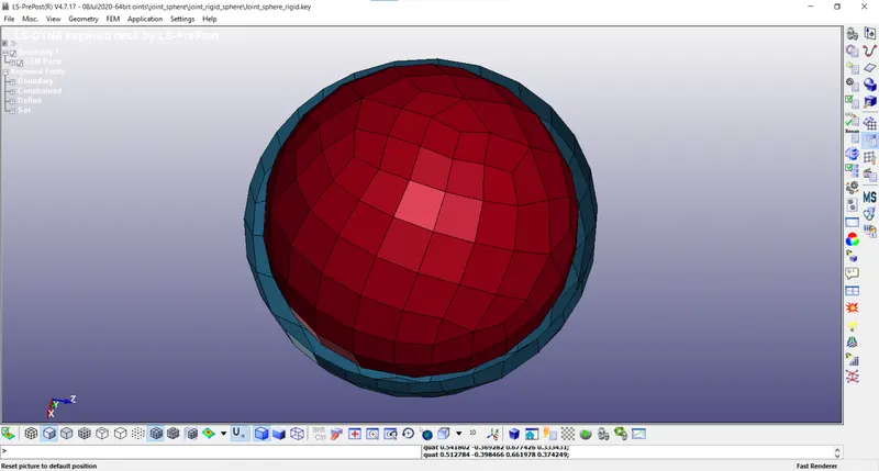
2. Creating the Constrained Nodal Rigid Bodies (CNRB)
Each different node of the Coincident pair is used for creating CNRB with different Spheres. Suppose, the nodes 306 and 307 are coincident then using the Node 306, the CNRB is constructed for the Sphere-1 and using the node 307 the CNRB is constructed for the Sphere-2. Hence, a total of two CNRB are constructed using the create entity tool bar. One of the coincident node becomes the parent node where as the other nodes are chosen to be as the child nodes.
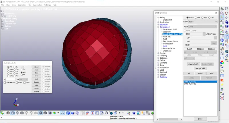
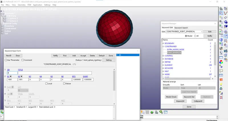
3.Creating the Spherical Joint
The spherical joint is created using the keyword * CONSTRAINED_JOINT_SPHERICAL.The Parent nodes of the CNRB are entered in the card in order to create the Spherical joint. N1 and N2 are the parent nodes connecting the Sphere-1 and Sphere-2.
4. Applying the Boundary Conditions
i.Applying the SPC to the Outer Sphere
Using the keyword *BOUNDARY_SPC_SET, the Outer cylinder is constrained in all degrees of freedom
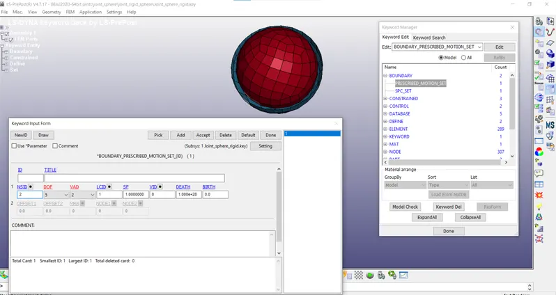
ii. Applying the Prescribed Motion Set to the Inner Cylinder
The rotational displacement is imparted to the inner Sphere using the keyword *BOUNDARY_PRESCRIBED_MOTION_SET. The nodeset belonging to the Inner Sphere is assigned the rotational displacement . The flag for the Rotational displacement about the x-axis and the displacement value is entered in the card. The load curve describing the rotational displacement with respect to the time is defined and assigned in the card.
CASE 4: CREATING THE TRANSLATIONAL JOINT
All the steps in this case are similar to that of the CASE-1 except 1,2,3 and 4. Instead of these steps, the following steps are executed.
1. Creating the Three pairs of Co- incident Nodes
Three pairs of Co-Incident Nodes are created along the axis of the two Co-axial Rectangular Boxes using the node edit option in the Mesh Tool.
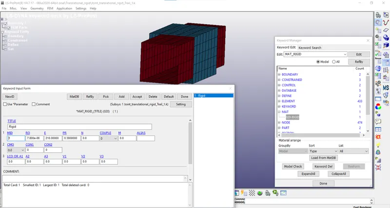
2. Creating the Constrained Nodal Rigid Bodies (CNRB)
Each different node of the Coincident pair is used for creating CNRB with different Boxes. Suppose, the nodes 1355 and 1356 are coincident then using the Node 1355, the CNRB is constructed for the Box-1 and using the node 1356 the CNRB is constructed for the Box-2. Hence, a total of Six CNRB are constructed using the create entity tool bar. One of the coincident node becomes the parent node where as the other nodes are chosen to be as the child nodes.
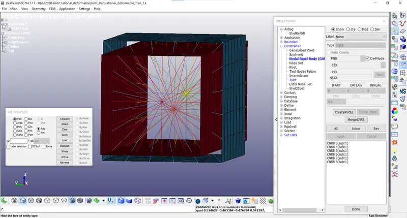
3. Creating the Translational joint
The spherical joint is created using the keyword * CONSTRAINED_JOINT_TRANSLATIONAL.The Parent nodes of the CNRB are entered in the card in order to create the Translational joint. N1, N3, N5 are the parent nodes connecting the Box-1 where as the Nodes N2, N4 and N6are the parent nodes connecting the Box-2.
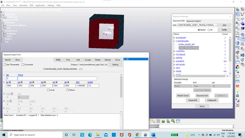
4. Applying the Boundary Condition
i. Applying the SPC to the Outer-Box
The Outer Box is constrained using the keyword *BOUNDARY_SPC_SET. The nodeset belonging to the outer Box-1 is assigned for the Single Point constraint in all degrees of freedom.
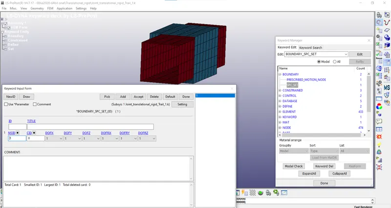
ii. Applying the Prescribed motion to the Inner Box
The Prescribed motion is applied to inner box using the *keyword BOUNDARY_SPC_SET. The flag value for the translational motion and the displacement is entered in the card. The curve describing the displacement motion with respect to time is defined and it is assigned in the card.
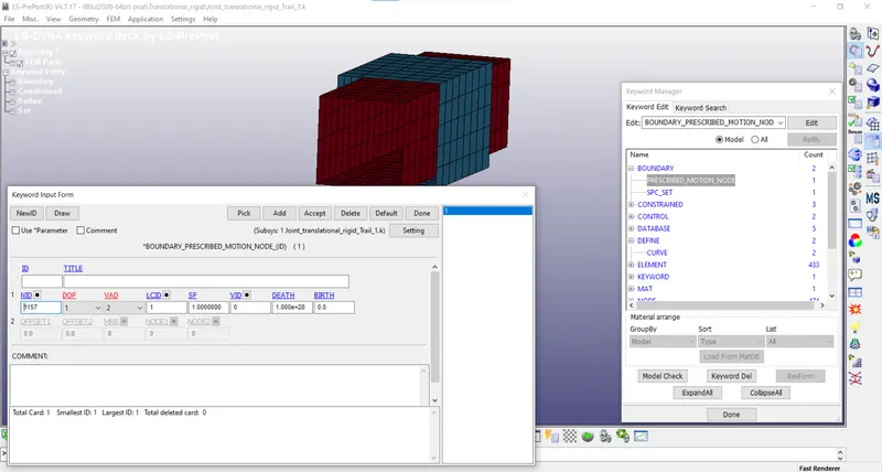
Results:
1. Revolute joint
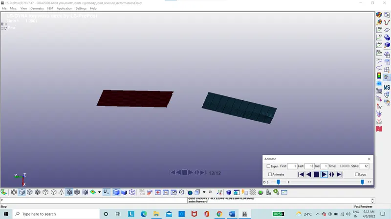
The simulation shows that the Plate-2 rotates about the axis created by the coincident nodes as the plate-1 is fixed due to the Constraint in all degrees of freedom. This way the revolute joint ensures that the plate rotates about an axis without the need for creating a local coordinate system and making the plate rotate about it.
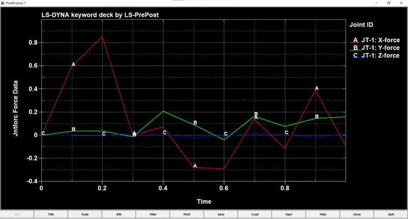
The Joint forces of Revolute joint with Rigid bodies are given as,
2.Cylindrical Joint
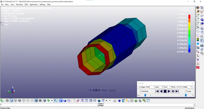
The simulation shows that the Inner Cylinder is able to rotate about the same axis as well as translate and hence allows the Cylinders to have reative motion about the same axis. This type of motion can be used for depicting the motion of the Screws.
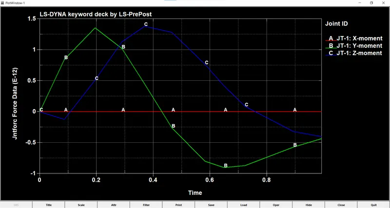
The Joint forces of Revolute joint with Rigid bodies are given as,
3.Spherical Joint
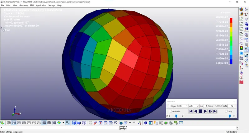
The simulation shows that the Inner sphere is able to have relative motion with respect to the Outer sphere and remain concentric irrespective of the direction of the rotation given to the Inner sphere.
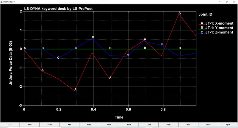
The Joint forces of Revolute joint with Rigid bodies are given as,
4.Translational joint
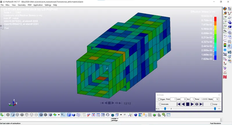
The simulation shows that the Inner Box is restricted to having only translational motion along the centerline and both the rigid bodies are stuck together.
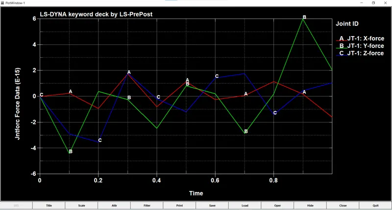
The Joint forces of Revolute joint with Rigid bodies are given as,
CONCLUSION :
1. All the joints are applied to problem statement successfully.
2. Results are derived.