Week - 9 Material Modeling from Raw Data
Aim:
To create a material model using the data extracted from the given true stress-strain curve of graphite iron cating using the dog bone specimen.
Note: The unit system used is kg-mm-ms.
Based on the characteristics of the material, the solver LS-DYNA has categorically classified material models. For example, *MAT_ELASTIC is an isotropic hyperelastic material model which can be used for beams, shells and solid elements. Apart
from the predefined models available in solver library, custom material models could also be used. LS-DYNA offers material models based on anisotropic plasticity, cohesive property, concrete property, composites, polymers, orthotropic, viscoelastic,viscoplastic strain rate formulation etc. Hence the user is allowed to select the material model based on the application.
Procedure:
Extract the data from the image file given.
Clean the data and visually confirm that it matches the original.
Convert the data to (kg-mm-ms) unit system.
Process the data and create the material as demonstrated.
Use the material model with a dog-bone specimen and validate the same.
1. Data Extraction:
The given image file of true stress-strain graph of graphite iron casting is opened in data digitizer software to extract the data and export it as excel file.The curve 2 is chosen to extract data of stress-strain of graphite iron casting as shown in fig.1.
Note: Ensure the data points picked is evenly spaced so as to get smooth curve and better convergence.
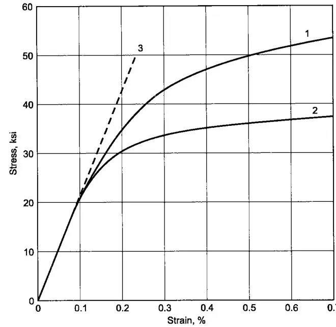
Consider the curve no 2 for extraction.
The following points were extracted from the grapgh image.
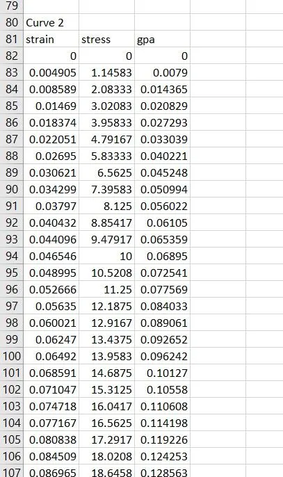
This extracted data is in raw form.So plot the stress Vs strain curve for the same.
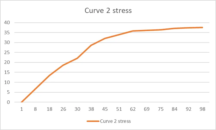
Now convert the Stress values from Ksi to GPa
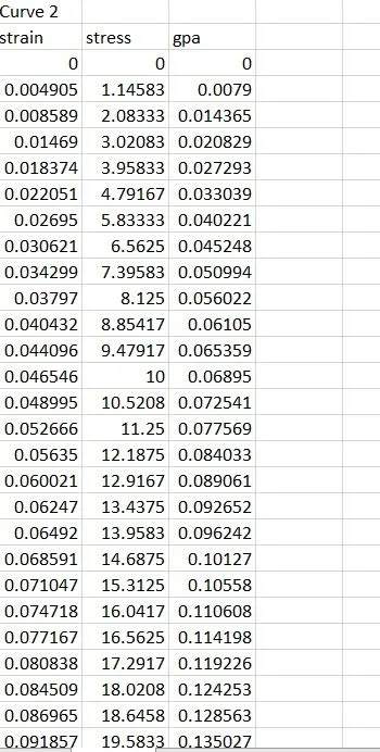
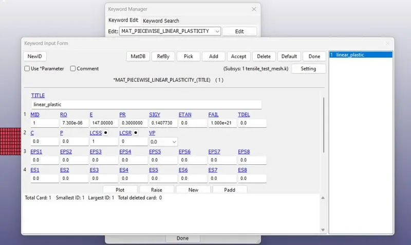
we calculate the young modulus by slope of the linear elastic region young modulus = 147.48 GPA
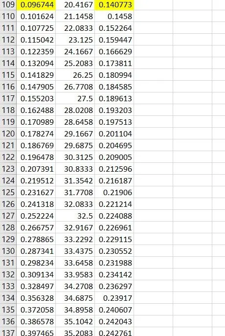
So need to define the yield limit from image it is observed that material linear elastic regioon end at about 20 ksi so our yield limit is 0.140773 GPA , from this point we define the plastic region.
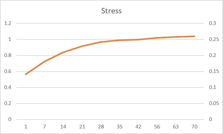
In LS DYNA plastic region is defined by curve between EFFEECTIVE PLASTIC STRAIN vs TRUE STRESS(correspond to the strain)
Case Set up:
1)Boundary Conditions
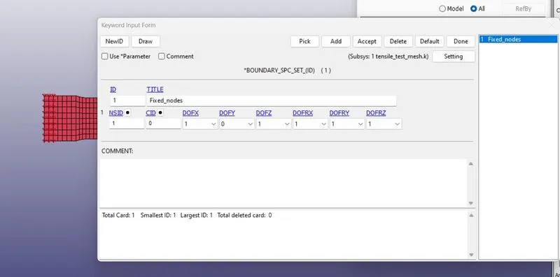
Create SPC
The nodeset at the on the edge of the Specimen in the left hand side (in the x- direction) are constrained in all the degrees of
freedom except for the traslational degree of freedom in y-direction.
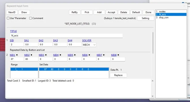
The Node set on the neutral axis have to be constrained for all the degrees of freedom except for the translational in x-direction.
ii. Creating the prescribed motion set card for applying the displacement
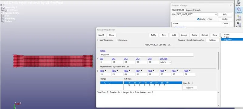
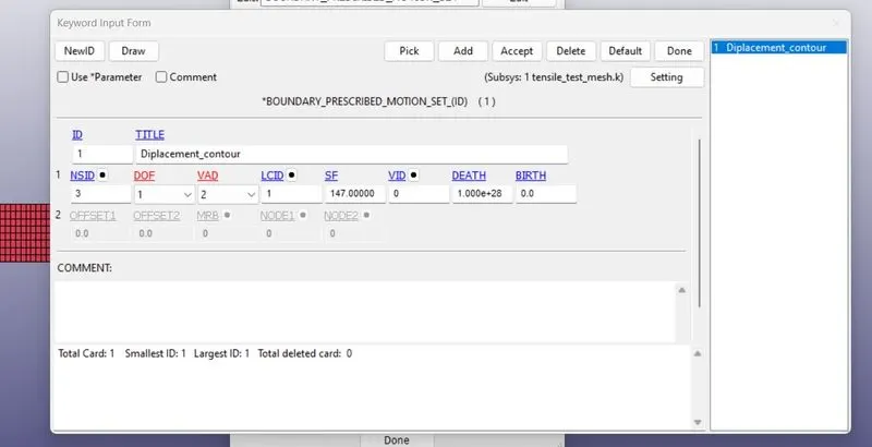
The Prescribed motion of displacement is applied to all the nodeset of the edge of the specimen in the right end( in the xdirection).The Prescribed motion of the displacement is applied in the x-direction.The displacement vs time curve is plotted and is assigned for the displacement in the prescribed motion set card.
Apply the displacement to other end of coupon.
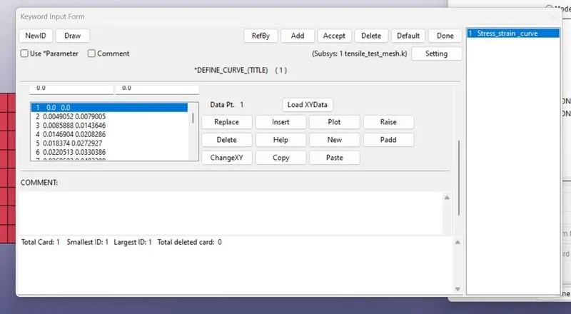
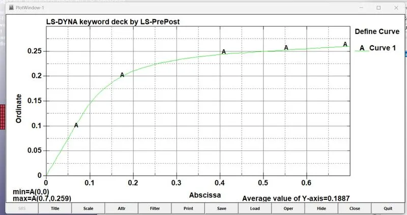
i. Defining the curve for the material
The data from the material model created is converted in to the comma seperated value (CSV)form. The CSV file is then
uploaded while defining the curve for the material.
ii. Creating the 024_MAT_PIECEWISE_LINEAR_PLASTICITY Material card
The material card chosen for this simulation is 024-MAT_PIECEWISE_LINEAR_PLASTICITY.
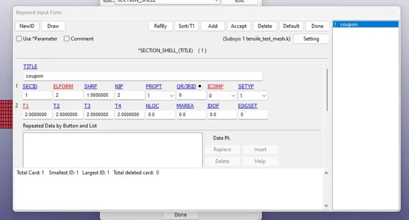
3)Create section shell properties for the given model.
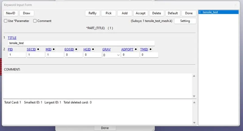
Assign the part ID and section ID.
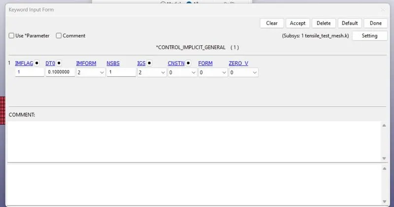
5. Creating the Control cards for the Implicit analysis
i. Adding the Implicit_Genral card
In addition to the already existing cards, the Implicit_general control card is added in order to carry out the Implicit analysis.
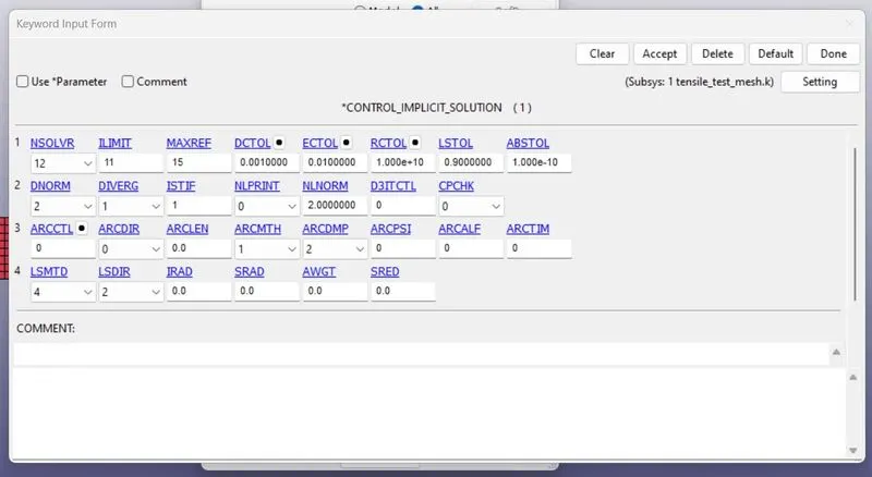
iii. Creating the IMPLICIT_SOLUTION card for setting the limit for the no of iterations.
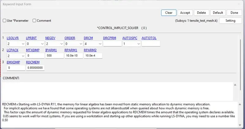
iv. Creating the IMPLICIT_SOLVER card
This an optional card which applies to implicit calculations.
6.Creating the Control termination Card for the runtime
The Simulation runtime is assigned by entering the ENDTIME in the Control Termination card that is created from the keyword
manager.

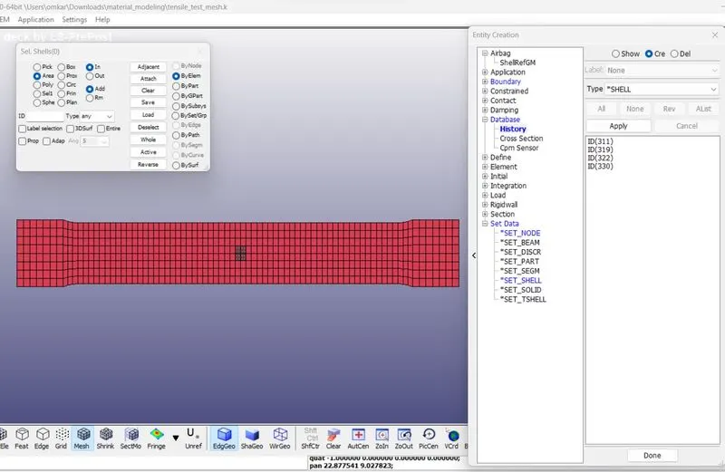
7.Creating the Time History card for the Element Output
The Keyword *DATABASE_HISTORY is created for the element whose stress and strain outputs are to be extracted with respect to time.
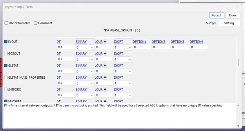
8.Create the database Ascii option card.
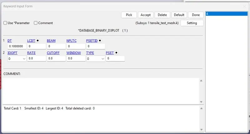
ii. Creating the binary D3Plot card for the animation output
The binary D3plot card with the timestep at which these outputs must be given out is mentioned in DT value.
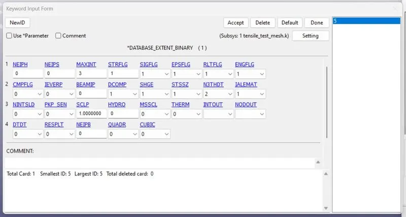
iii. Creating the Binary_Extent card for the Strain output
The Extent_Binary card is created under the keyword *database in the keyword manager.
Results:
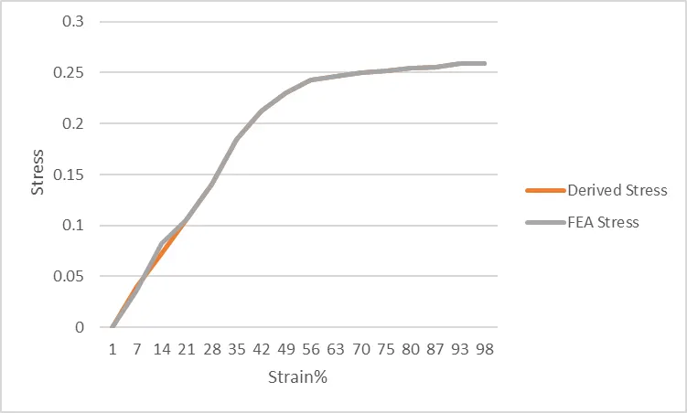
1.Comparison between FEA results with the extracted data of the Material