Week-6 Calculate the Stretch Ratio by comparing the ELFORM (-2,-1,1,2) with Ogden_Material Model.
INTRODUCTION:
Ogden material model is a hyperelastic material model used to define the non-linear behaviour of materials like rubber and polymers. This material model is generally used for materials showing incompressible, isotropic and non-linear stress-strain behaviour.
In this study, a solid cube of rubber material modelled by Ogden material model is simulated for tensile behaviour. Different element formulations are used to compare the stress vs stretch behaviour.
Procedure:
1)Create solid box of 10x10x10 mm.
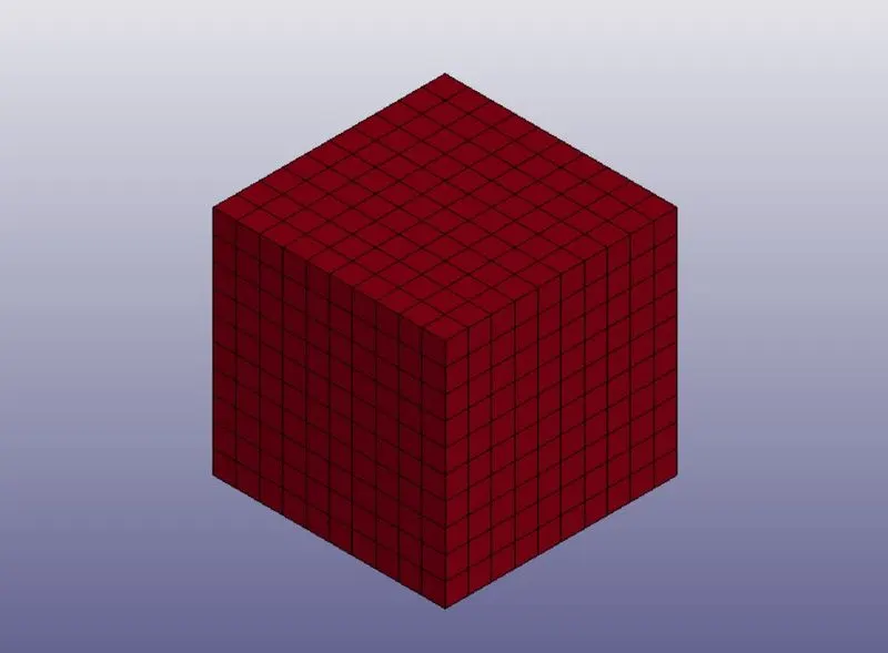
2)Now create different ELFORMS for solid cube as follows
Define seperate section for each boundary condition.
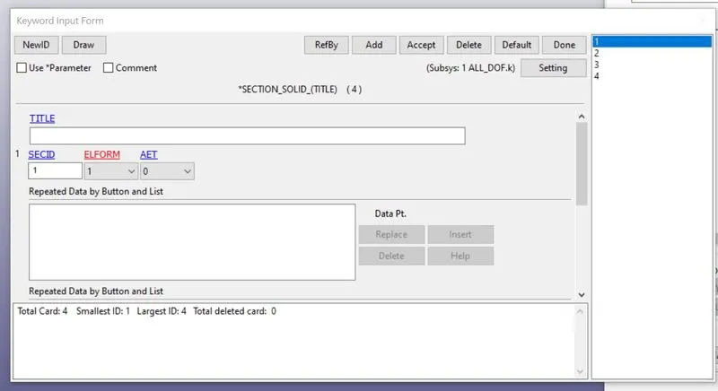
3)The section id is changed for each simulation.Now for tensile test, the cube will be pulled in one direction while the nodes will be restricted in another. So we apply prescribed motion to one set of nodes while other set of nodes on the opposite face has been constrained using SPC card.
There will be shrinking in the z and y direction of the nodes. But the centre nodes will remain in place and hence will beconstrained in the direction normal to the applied load. The appropriate boundary conditions are given in the images below:
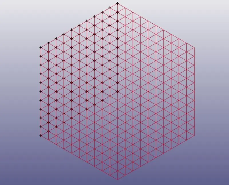
Fig a: prescribed motion nodes in the positive x-direction
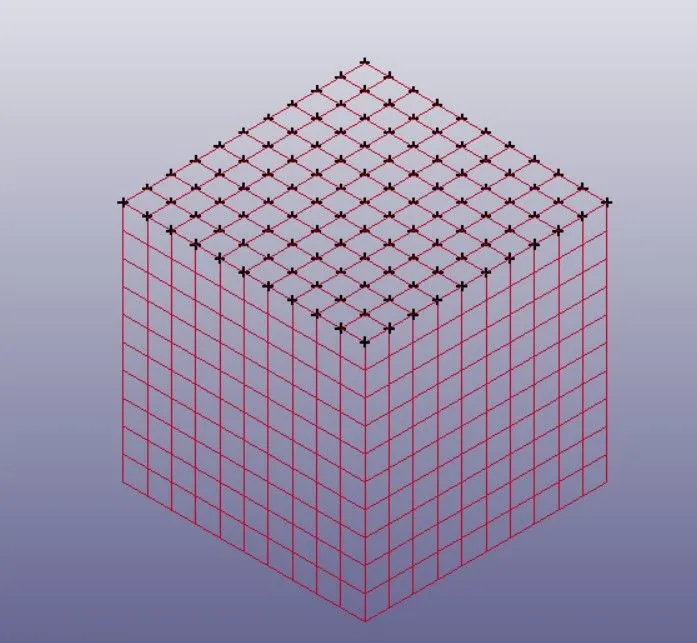
Fig b: Nodes being constrained using spc in the upper face
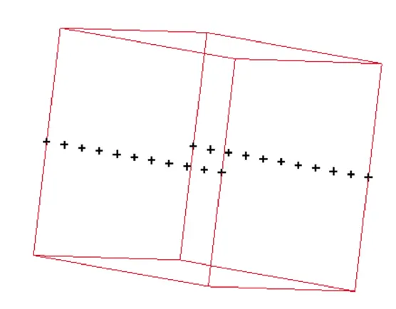
Fig c: The nodes being constrained in translation y for loading in normal direction
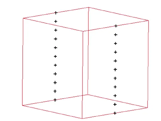
Fig d: The nodes being constrained in translational y direction
4) Now the displacement is given for each ELFORM
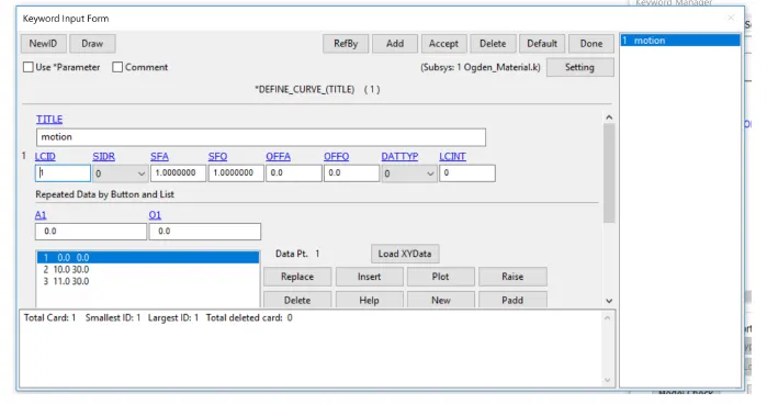
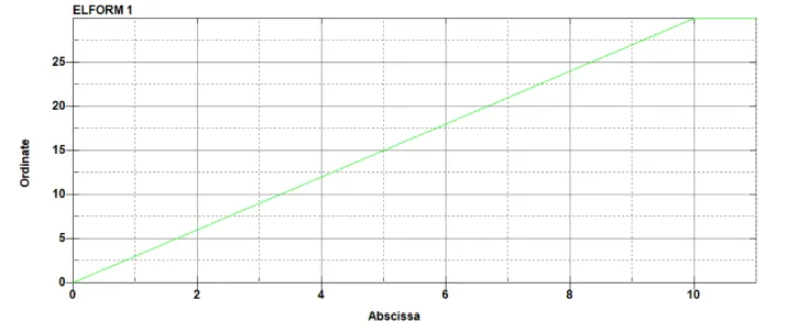
Fig: The displacement curve for prescribed node set.
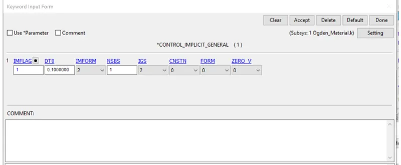
As implicit analysis is defined for this problem, the implcit cards Control_implicit Auto, Control _General, are set up.
The IMFLAG value is switched to 1, dt value is set to 0.1, ITEOPT and ITEWIN are kepts as 11 and 5. The dt_min is set as 0.001while the dtmax is set to be 5. Using the Control termination card, the end time is set to 10.
5)Databse extent binary and database d3plot cards are defined to get the stress-strain outputs. I thedatabase_extend_binary card, the STRFLG is set to 1.
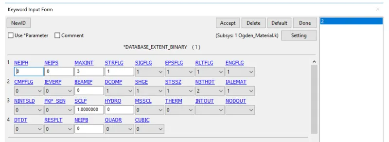
Fig: Databse extent binary card
6)Now after running the analysis, we get output in terms of true stress and true strain. This has to be converted to engineeringstress-strain using the following formulas:
εtrue = ln(1 + εeng)
σtrue = σeng ⋅ (1 + εeng)
stretchratio(λ) = (1 + εeng)
7)Results:
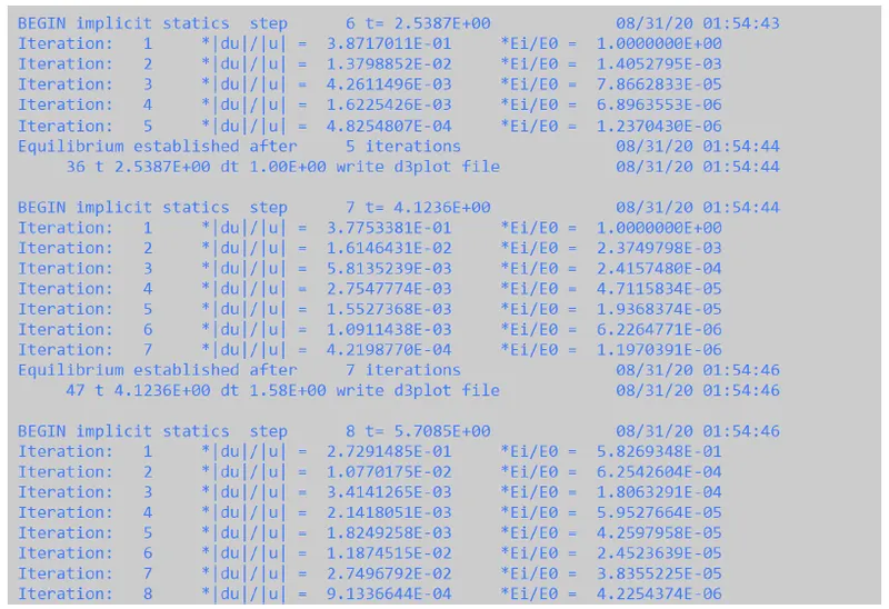
As we can see from the figure below, implicit analysis is used to solve the problem. The tolerance values are checked for everyiteration. The step repeats till termination time.
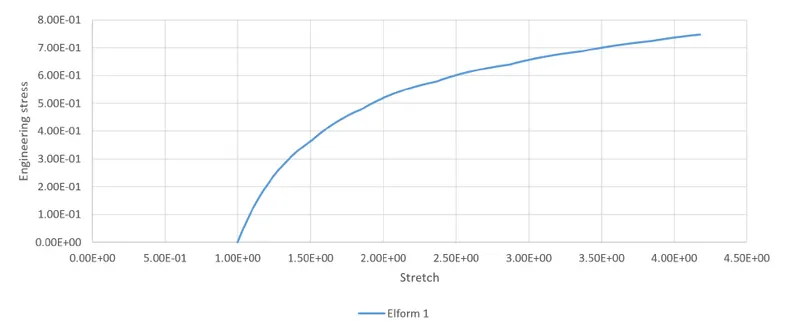
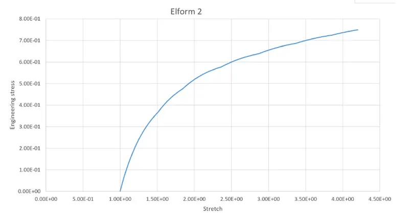
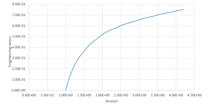
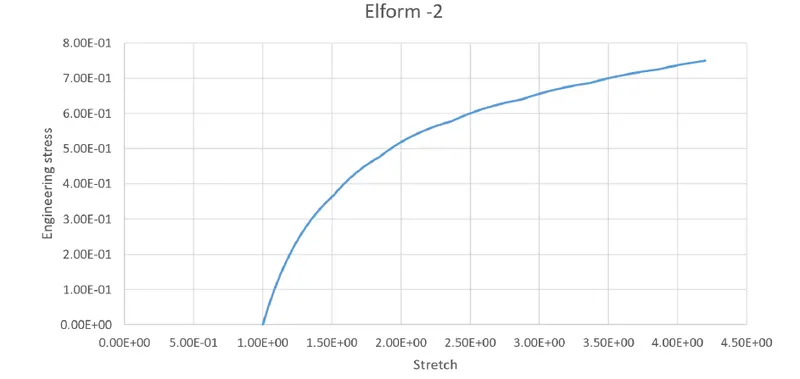
The output plot for engineering stress vs stretch ratio is given in the figure below:
The output plot for engineering stress vs stretch ratio is given in the figure below:
7)Conclusion:
1)The different elforms show same behavior in terms of stress and stretch but there lies a difference between computational timefor different element formulations.
2)This difference is low for the tensile test problem but will elevate for complex geometries with more non-linearties and fine mesh size.