Week - 4 - Crash Box Simulation
Aim:-To create a complete simulation file for crash analysis of a crash box having two different thicknesses of 1.2 mm and 1.5 mm from the given FE model of the crash box and produce the following deliverables.
- Input. k file and output files (D3PLOT, GLSTAT, SLEOUT, RCFORC)
- Animation of the final simulation
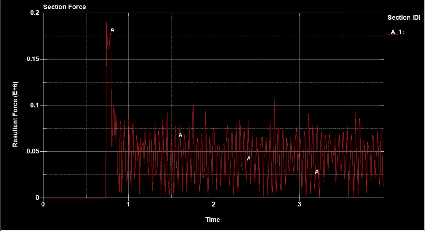
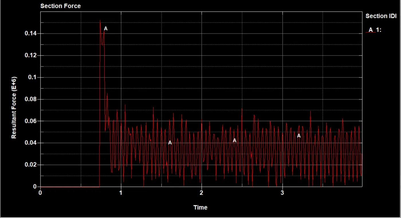
- Cross-sectional force generated in the middle of the crash box (along its length)
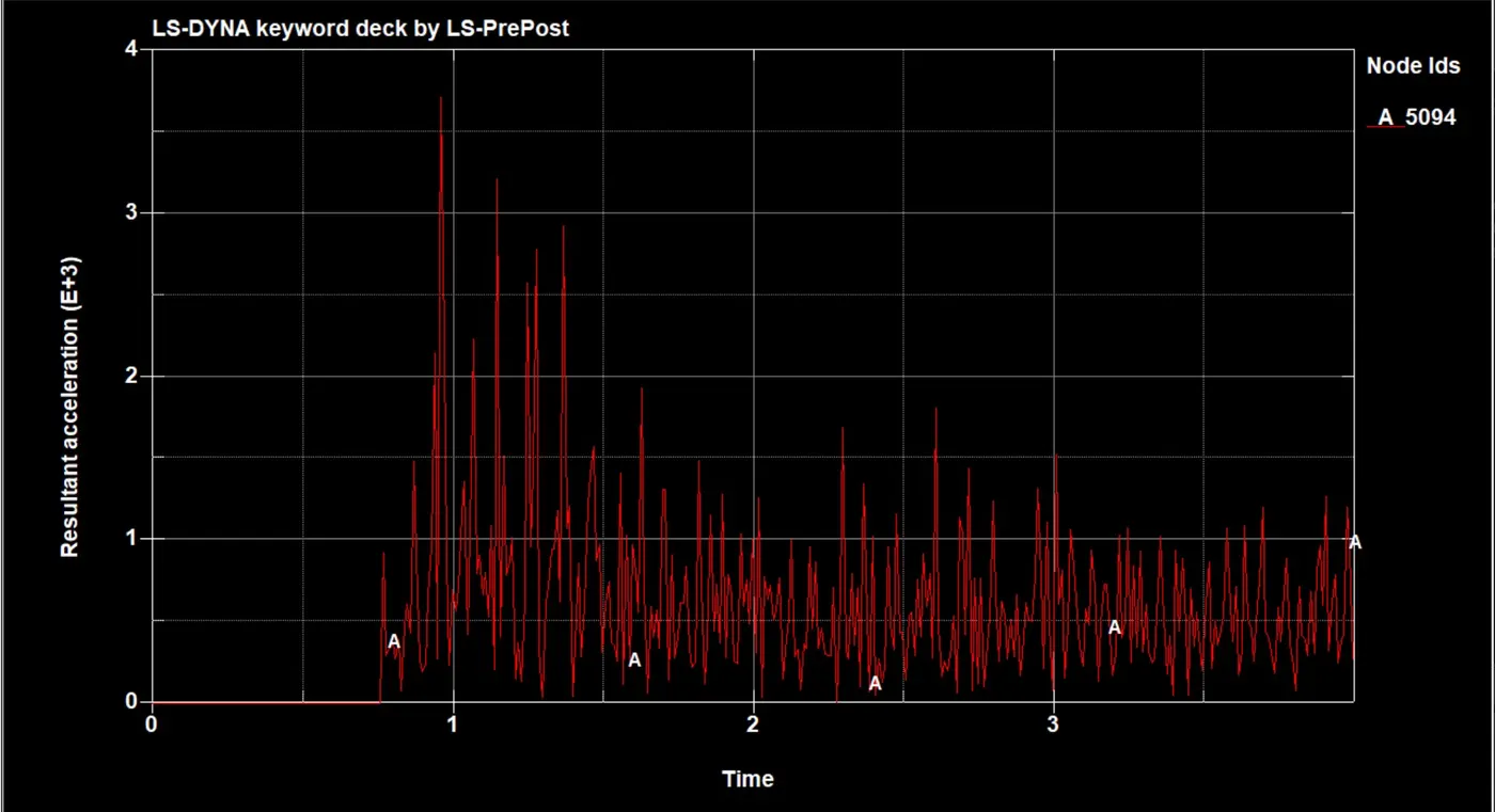
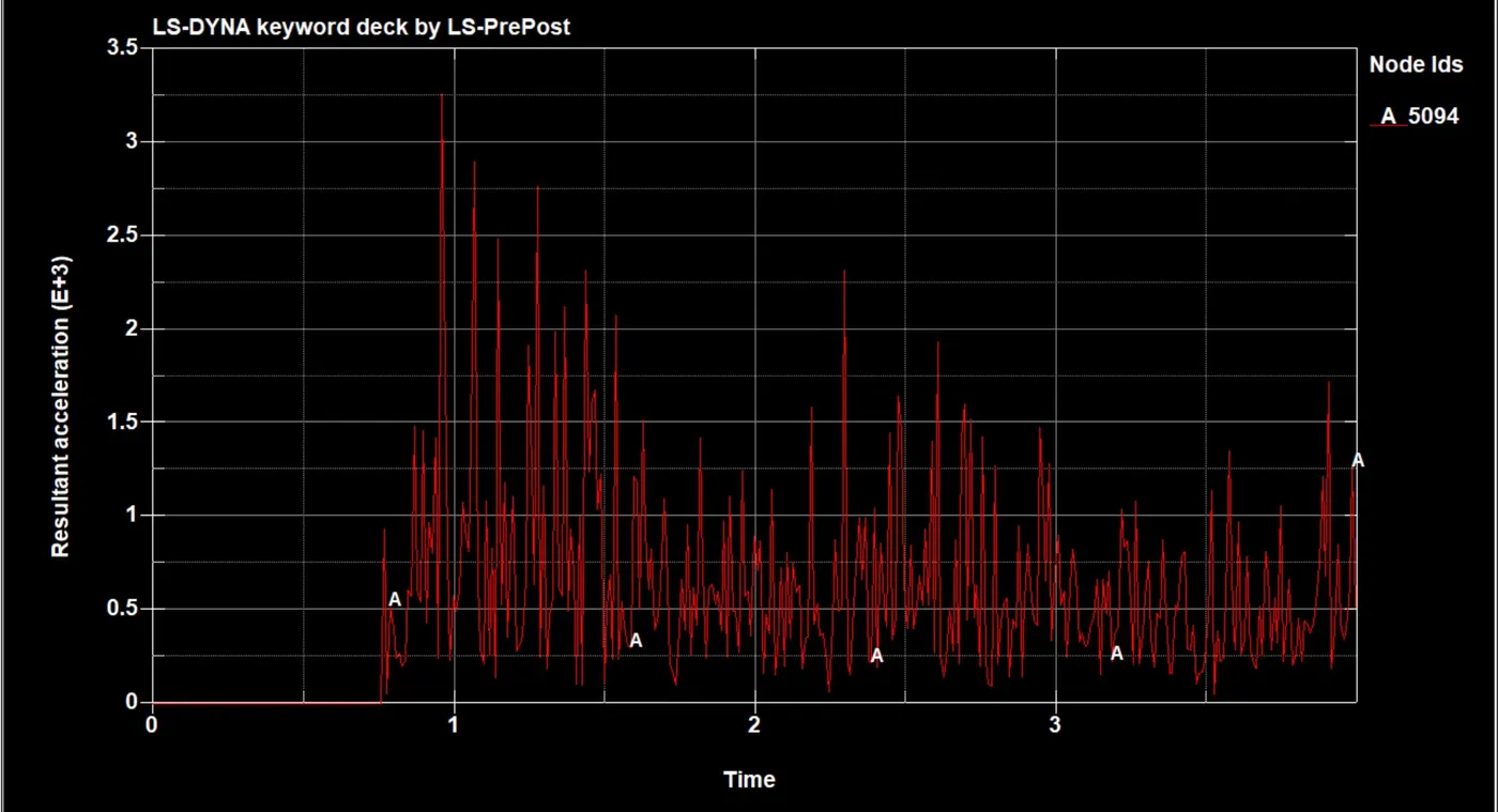
- Acceleration plot of a node in the middle of the crash box (along its length)
- Maximum directional stress and strain along the length of the crash box (X strain, Y strain, etc.)
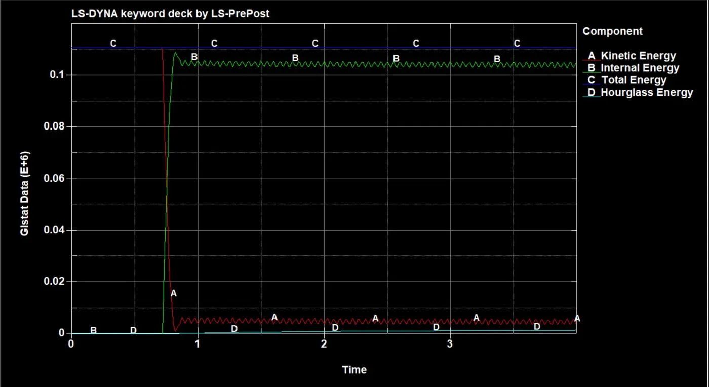
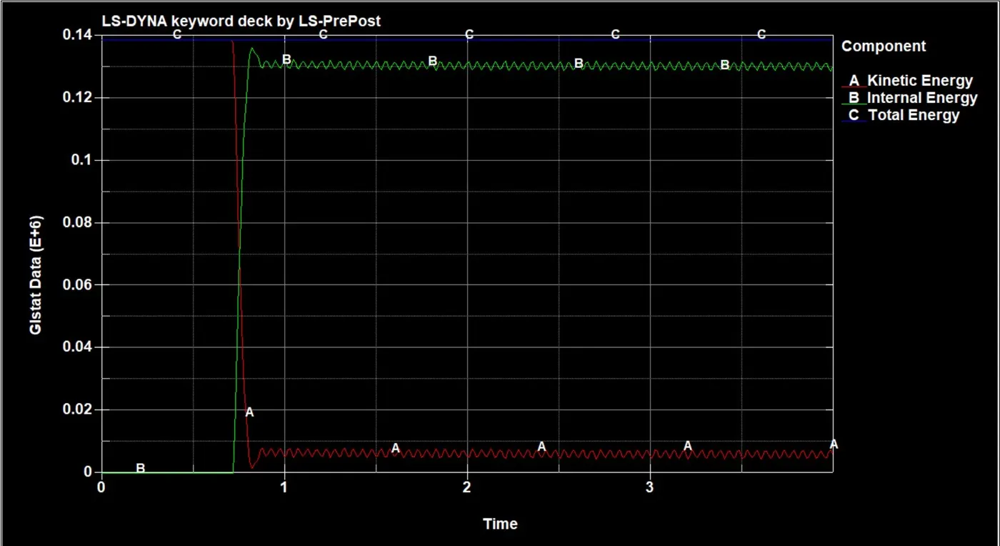
- Plot of all energies (total, internal, kinetic, hourglass, sliding)
- Compare the accelerations and stress/strain plots of 1.2/1.5mm crash boxes.
INTRODUCTION:-A crash box is a highly energy-absorbing structure that crashes on the application of loads and reduces impact on other components nearby. A full-fledged crash box is a highly sophisticated design but, in this case, a rectangular channel structure is considered the most simple crash box.
Following are the different assumptions and information required:
- The crash box should crash into a rigid wall created using *RIGIDWALL_ keyword.
- The material for the crash box is Elastic which is steel in this case.
- The unit’s system used is gm-mm-ms.
- Thickness of the crash box is 1.2 mm.
- Initial velocity for the crash box is around 50 kmph , which will be converted into gm-mm-ms.
- The simulation should satisfy the condition that It crashes on the rigid wall and rebounces completely.
Once the simulation is completed, results are collected in the form of graphical data and another simulation is executed by increasing the thickness of the crash box from 1.2 mm to 1.5 m.
PROCEDURE:-
The section describes different stages to set up the simulation file using LS-DYNA. These stages can be broadly categorized into creating an input deck containing cards such as contact, control, database, element, hourglass, initial_velocity, keyword, MAT, node, part, section, and title. Since LS-DYNA does not have a default system of units, therefore, the user needs to input material properties and physical dimensions according to a consistent system of units as per their choice and in this case, it is gm-mm-ms.
Import the .k file:-
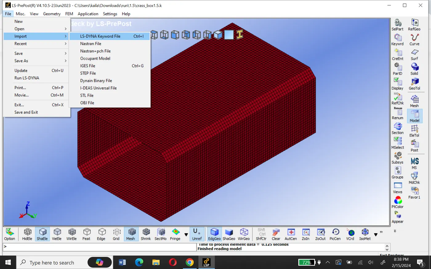
Import the .k file on the physical screen of the software using File > Import > LS-DYNA Keyword File.
Rigid wall:- Rigid wall mimic surfaces or volume that are frequently used to represent stiffer structures that are either stationary or in motion.
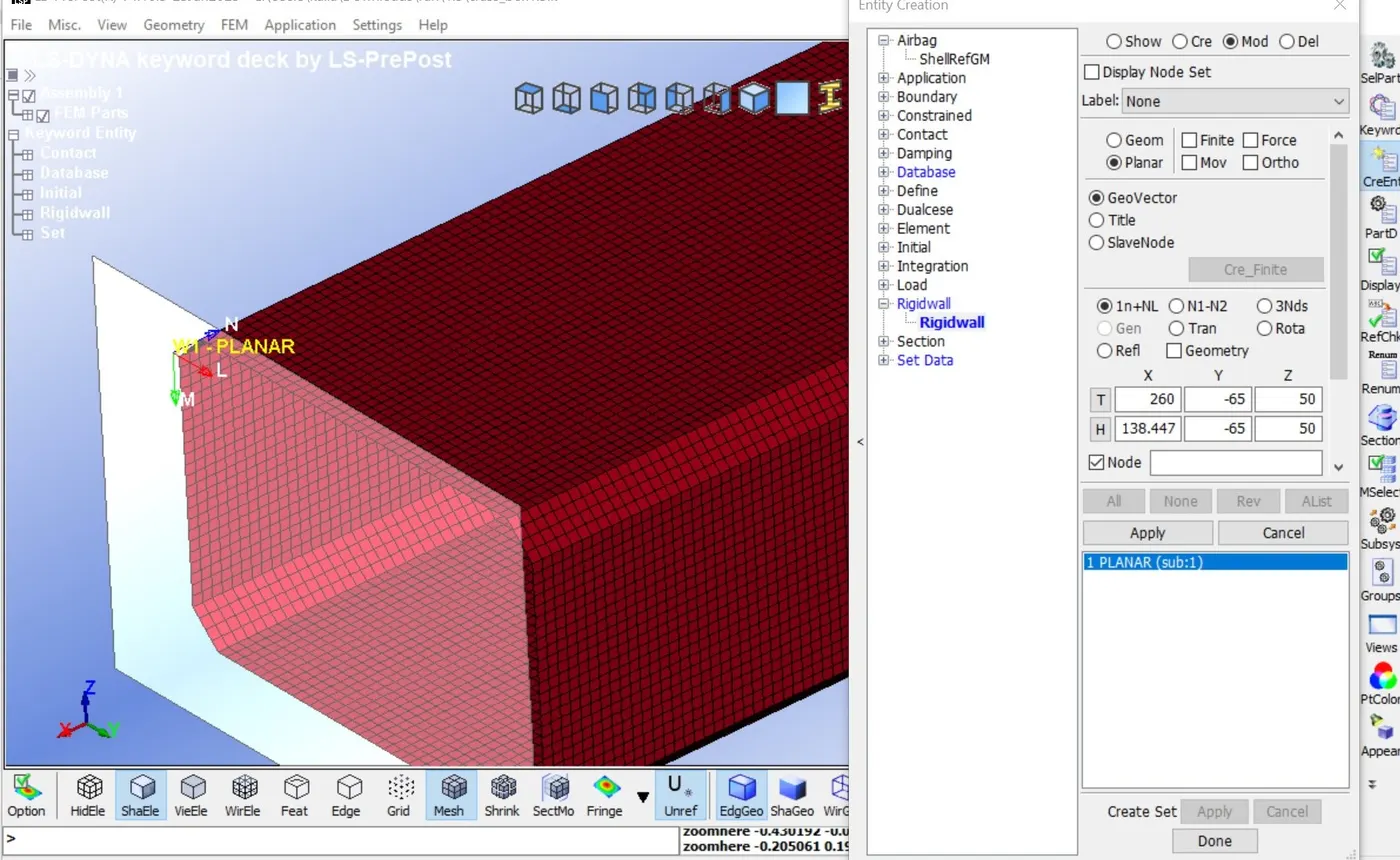
A stationary planer rigid wall is created ahead of the frontal portion of the box by selecting a node on the edge, select the planer option, and Geo-vector >1n+NL.
Note:- your rigid wall normal and box velocity direction should be opposit.
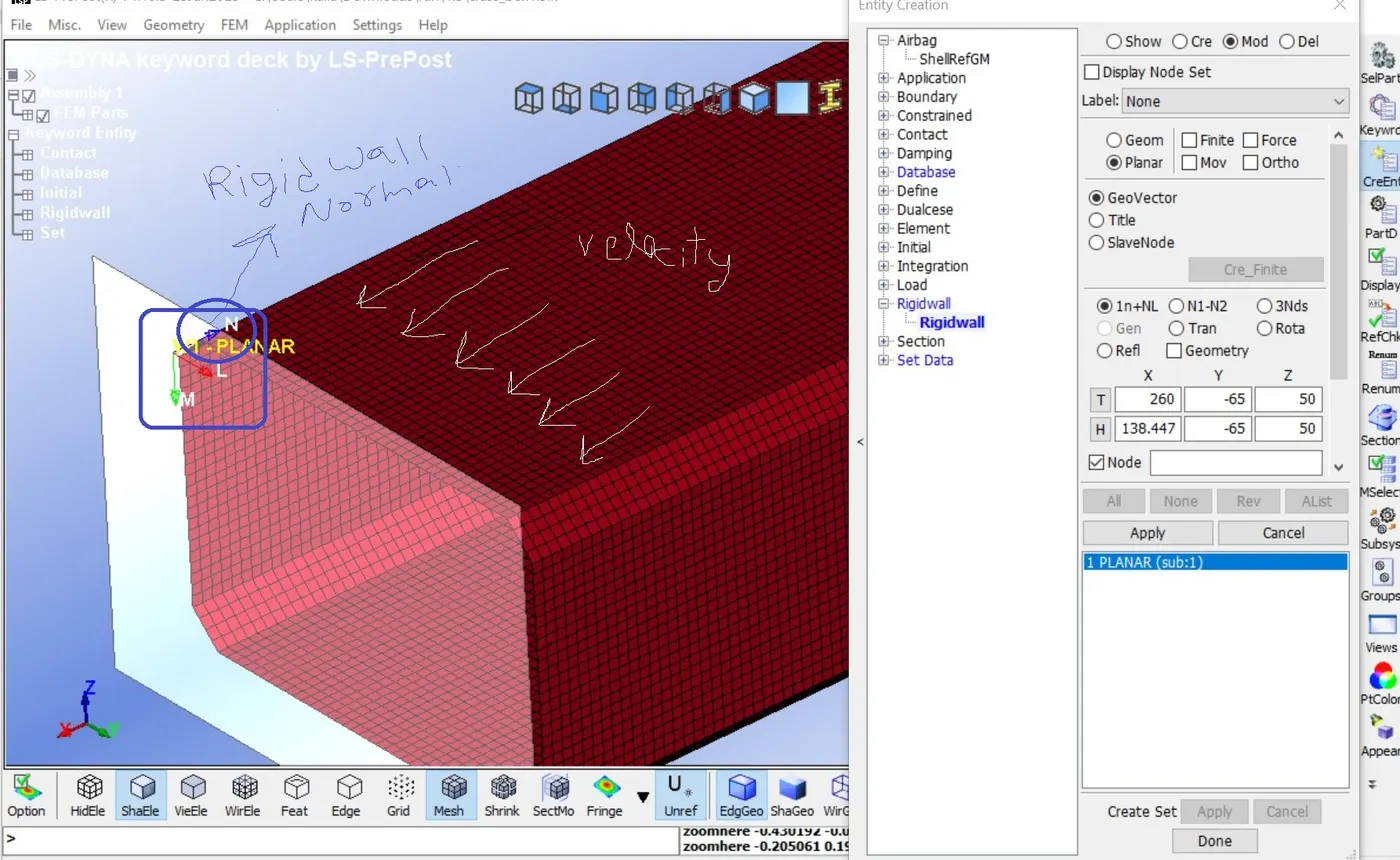
Now translate the rigid wall to some distance in the direction of the velocity of the crash box.
Initial velocity:-
Before creating initial velocity keyword, we must create a node set (NSID) for all the shell elements of the crash box.
Go to create entity > under set data > create a new set of node by selecting all the element of the box.
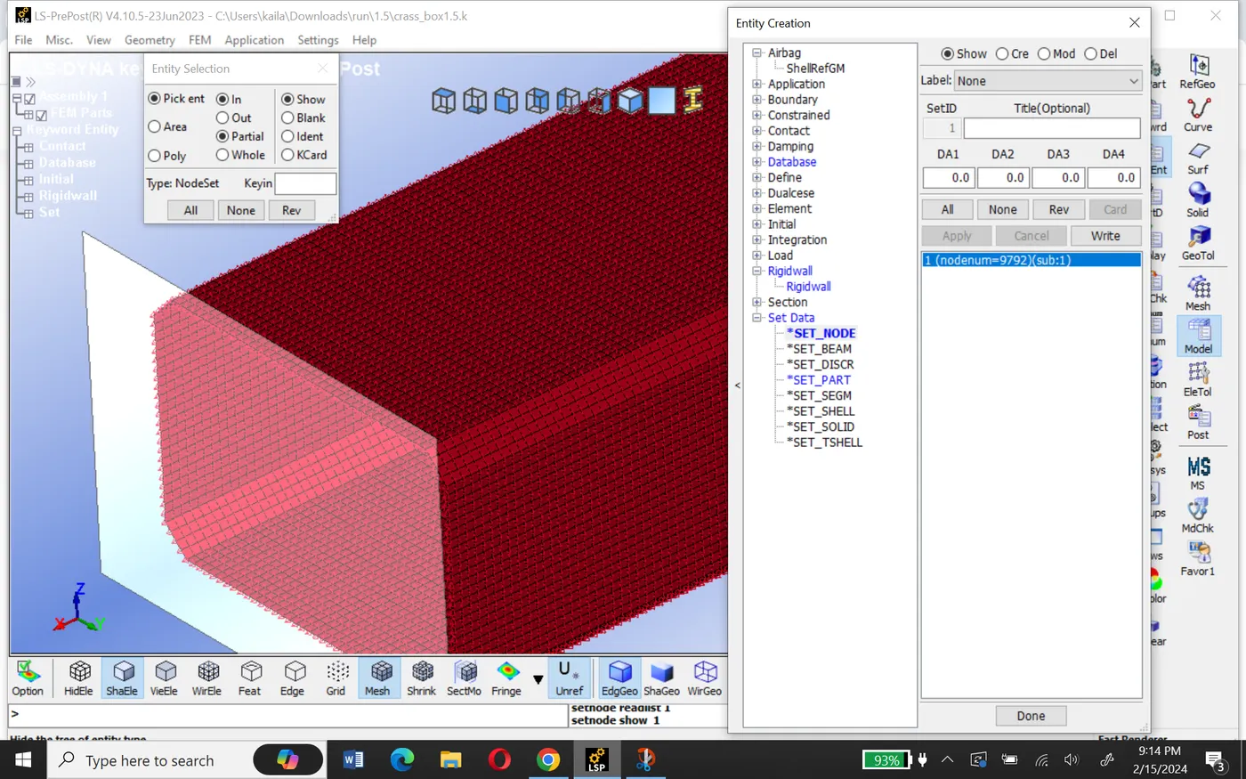
Now assign that NSID in the initial velocity as shown below.
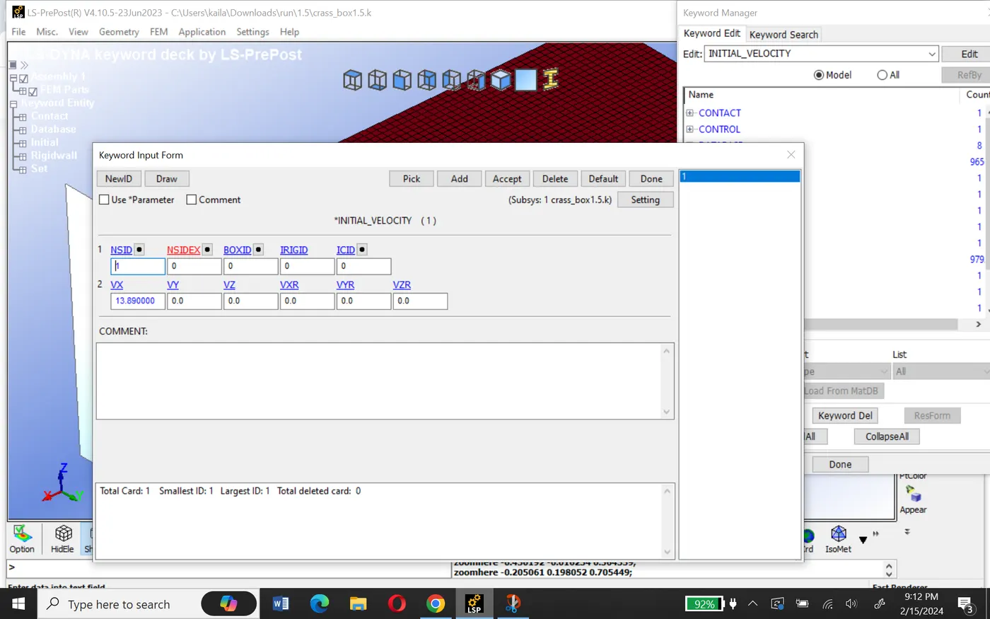
50 kmph=13.89 mm/ms
Shell card section:-
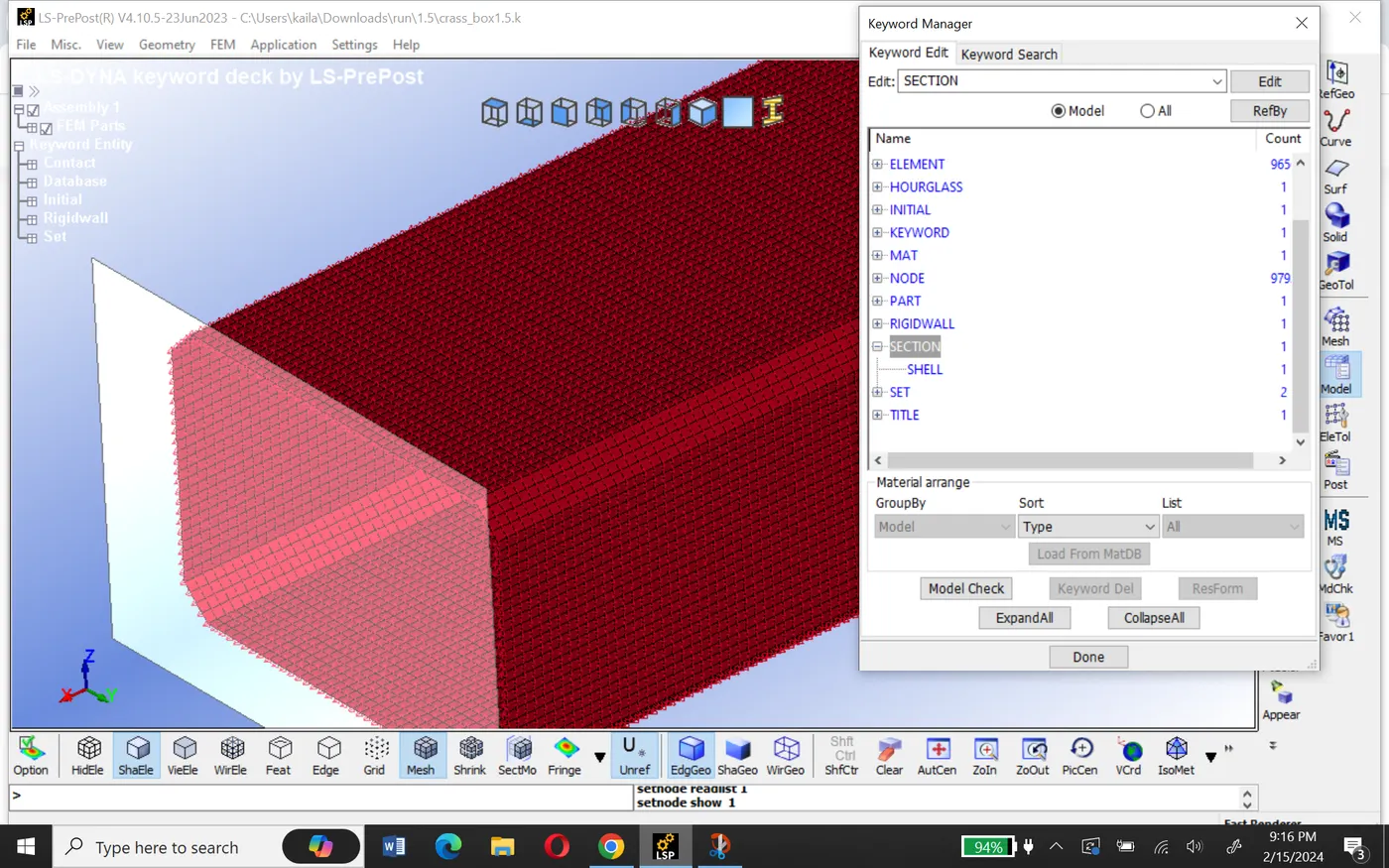
Shell card section is required to define section properties for shell elements.
go to keyword manager select section > shell >section Id and title
Choose element formulation value in ELFORM as 2(Belytschko-Tsay type elements )
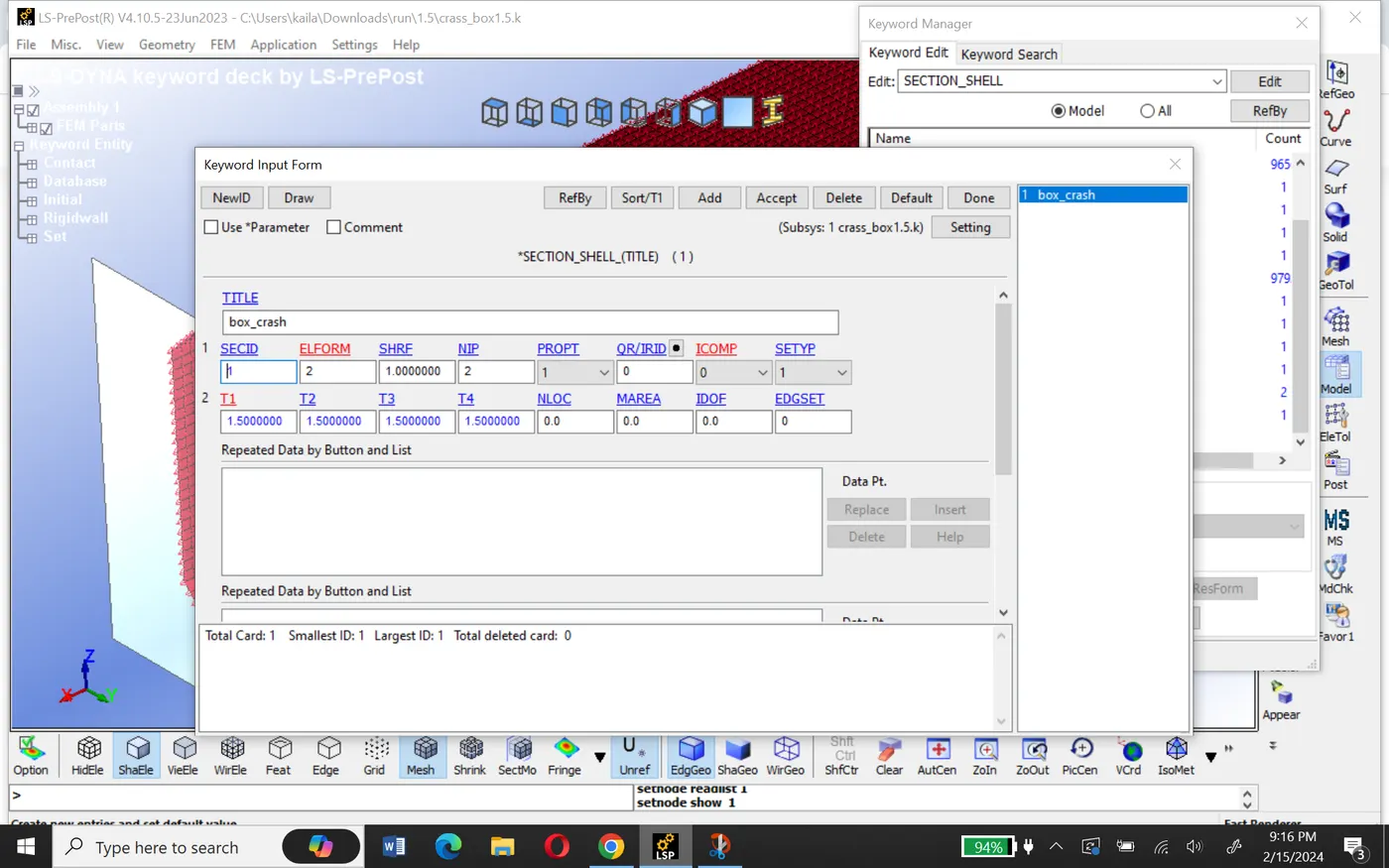
Mention the thickness of the shell element as 1.2 mm for one simulation and 1.5mm for another simulation.
Material card:-
For the crash box, we will assign the material as steel which is a non-linear characteristic material.
go to keyword manager
select Mat> Elastic material card and give material and title.
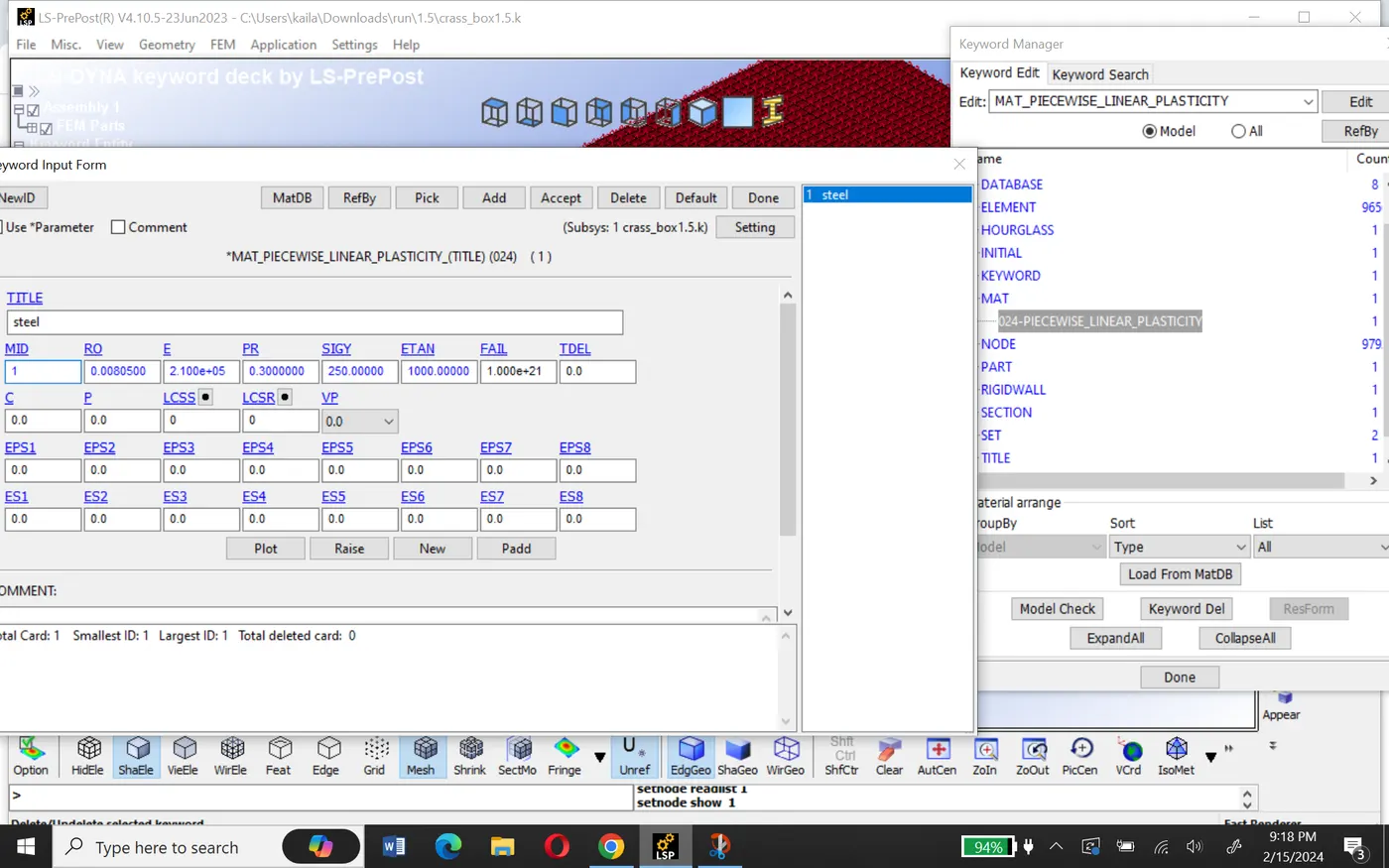
As we are using a gm-mm-ms units system, we will provide the characteristic value of steel as follows:
- Density of steel (RO)- 8.05*10^-3 gm/mm3
- Young's Modulus (E)-210*10^+3 mpa
- Poisson's ratio (pr)-0.3
- Yield stress (SIGY)-250 mpa
- Tangent modulus (ETAN)-1000 MPa
Hourglass:-
Hourglass can be defined using HGID. This keyword is used to reduce or control hourglass energy during the simulation.
Go to the keyword manager and select the values as shown below.
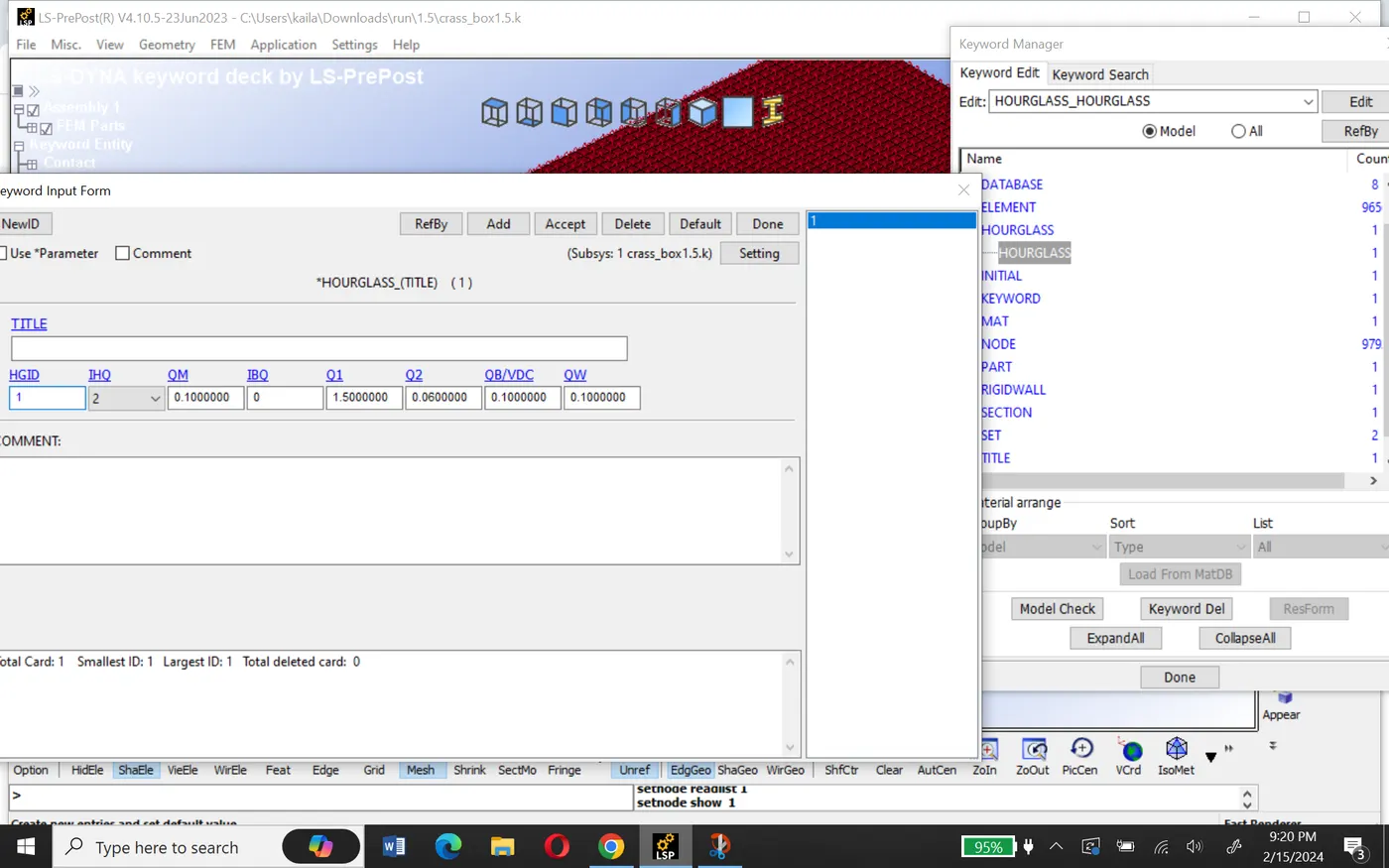
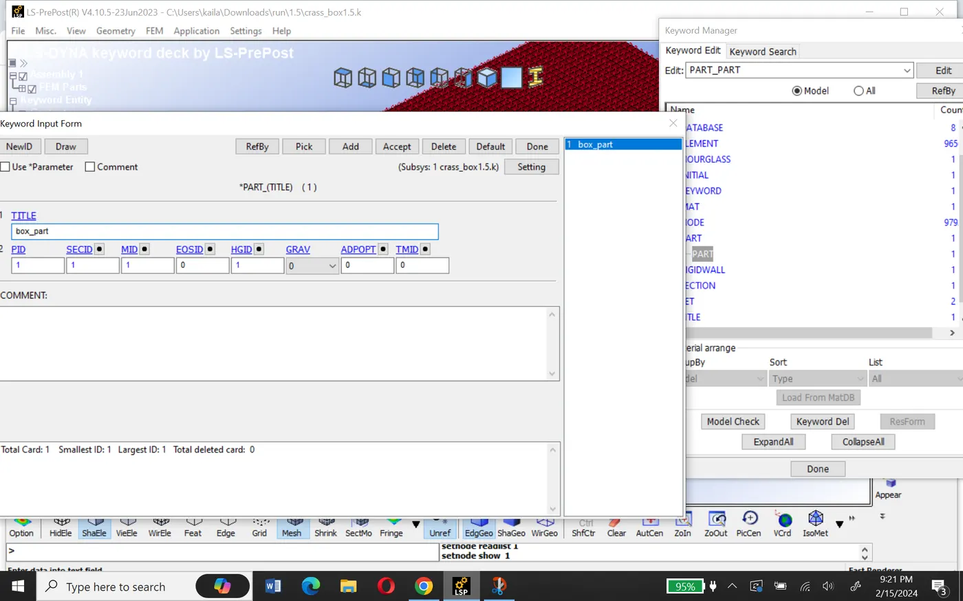
Now assign all the characteristics to the crash box part in the part keyword as shown below.
Contact:-
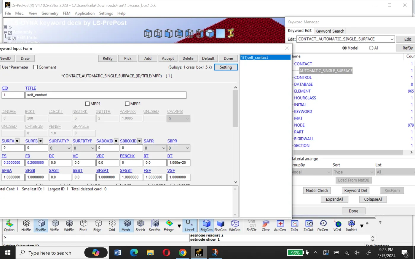
contact card can be used to define self-contact for the crash box as the crash box elements can have contact between themselves after the deformation.
Therefore define AUTOMATIC_SINGLE_SURFACE contact with the coefficient of friction of 0.2 as shown below.
Control:-
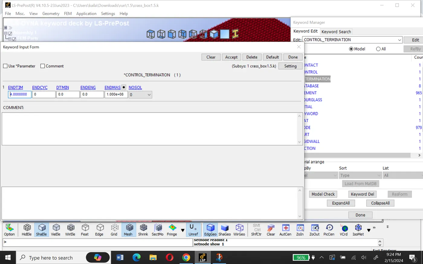
Define the termination time of the simulation which is necessary to run the simulation. The termination time is given as 4ms control_simulation keyword as shown below.
Cross-section:-
cross-section can be created under the database keyword to measure all cross-section forces.
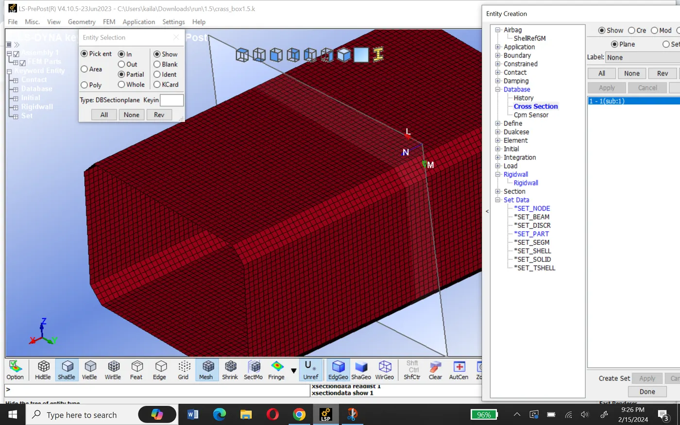

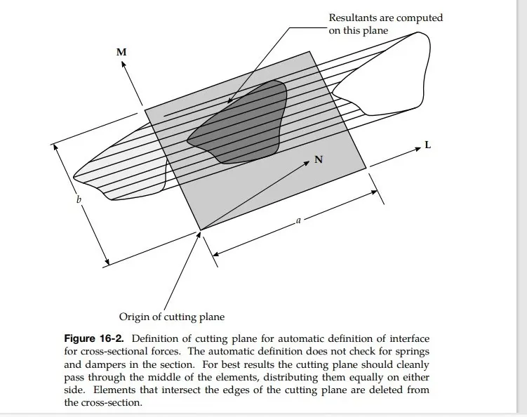

usually, two-row elements are selected as a section or a simple plane creation can also be done.
History node can be used to know the acceleration at the node during the simulation.
Post-processing results:-
The request outputs are d3plot, history node, and Ascii option are
- ELOUT: Element data
- GLSTAT: Global data
- MATSUM: Material energies
- SLEOUT: Sliding interface energies
- NODOUT: Nodal point data
- SECFORCE: Cross-section force
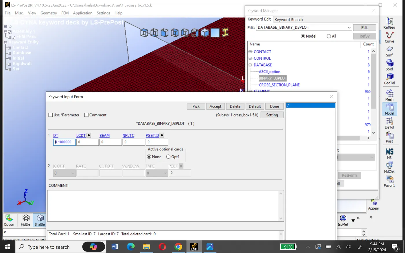
Model checker:-
since there are no errors, we can run the simulation.
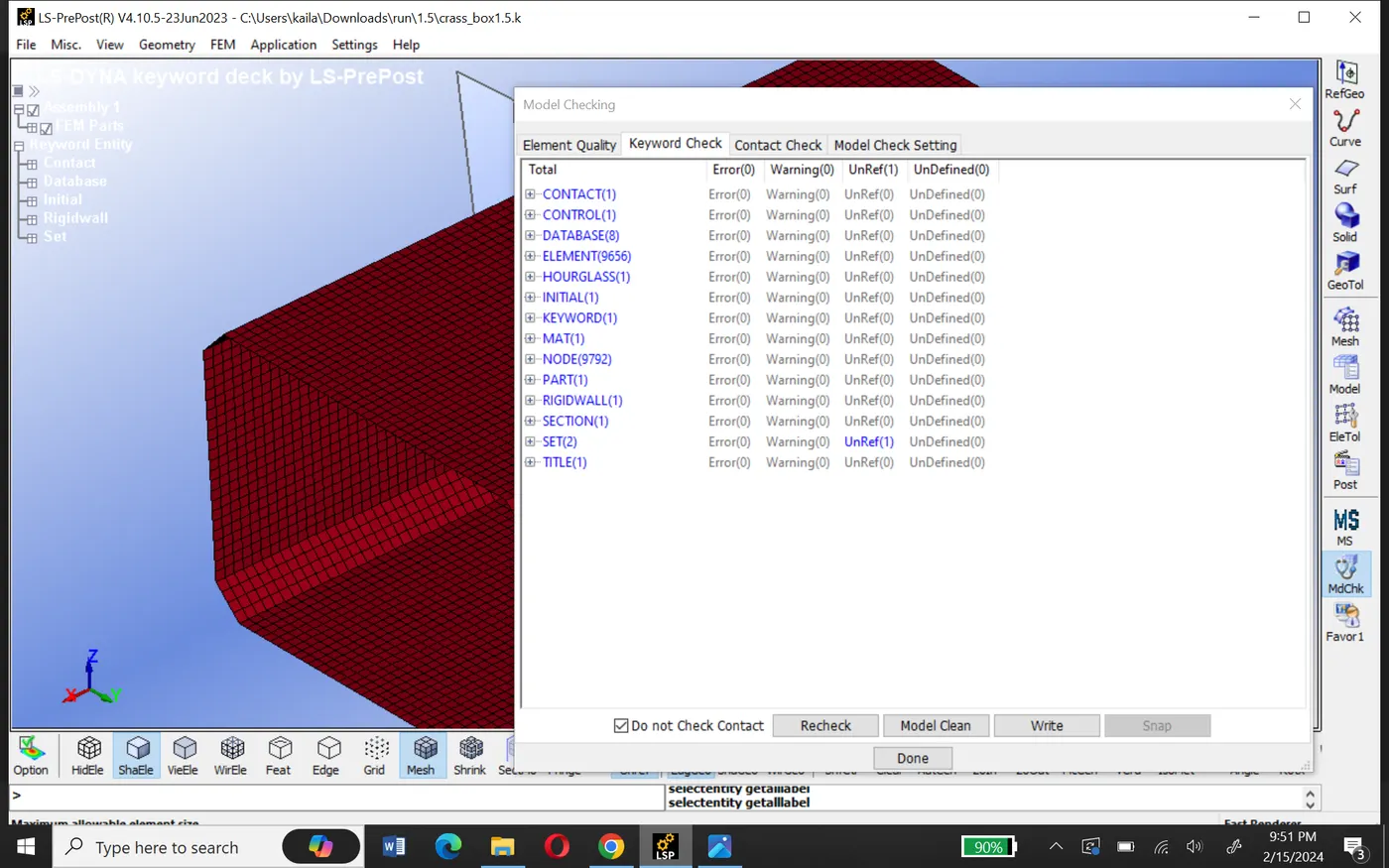
After creating all the necessary files for the simulation and check the model, we will save the model as the keyword file with .k extension.
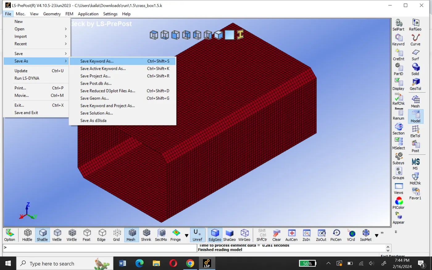
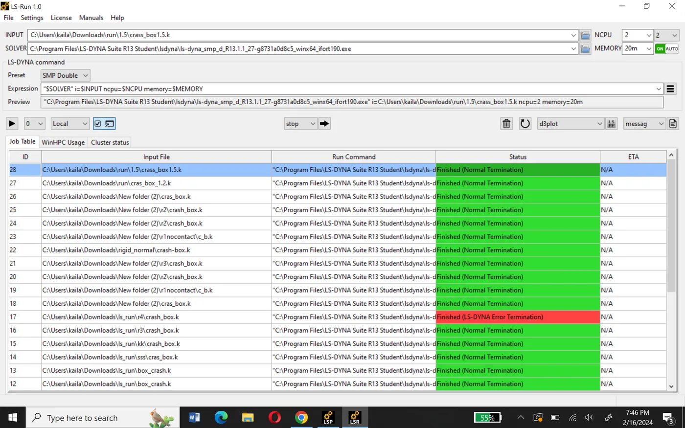
To run the model, we will go to file>Run ls-dyna. we will browse this file and again open ls-dyna import this file in the ls-run and run the file with 1.2mm thickness and after that run again with 1.5mm thickness.
Results and plot:-
To run the simulation, we will open the binary d3plot file from the specified path. Then we will click on play button on animation Toolbar. The resulting animation is shown below.
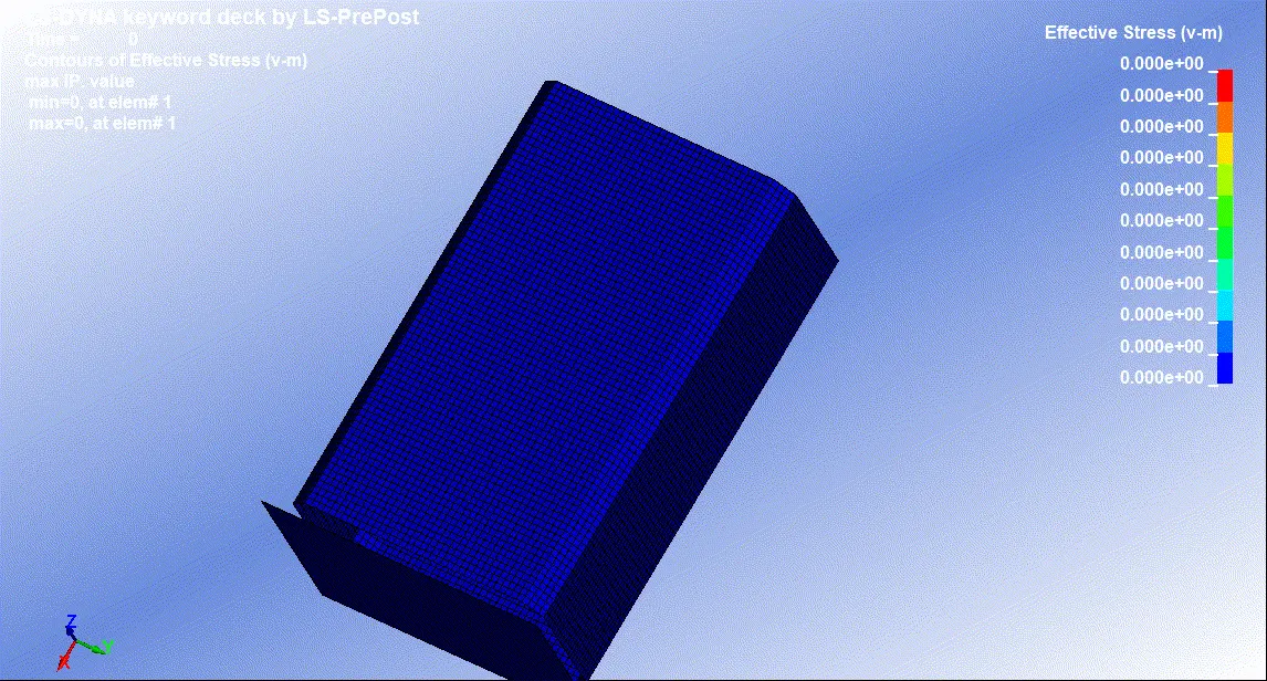
| crash with 1.2mm thickness | Crash with 1.5mm Thickness |
|
nitially, we can say that the velocity is maximum therefore kinetic energy is also maximum. But during the impact at 0.720ms kinetic energy is absorbed by the part and it decreases, simultaneously internal energy increases. Total kinetic energy converted into internal energy and also the hourglass produced is negligible. This is why the total energy remains constant. |
If you carefully compare the energy gaps, total energy slightly increased as the thickness increased simultaneously kinetic energy increased. |
|
|
 |
|
|
 |
Conclusion:-
crash box simulation is done successfully with 1.2mm and 1.5mm thicknesses respectively. All the objectives are fulfilled. From comparing the plot and animation we can say that the simulation result will be changed as the thickness of the model changes.