Week 4 - CHT Analysis on Exhaust port
Conjugate Heat Transfer Simulation
1. Give a brief description of why and where a CHT analysis is used.
Conjugate Heat Transfer (CHT) analysis is a computational technique used in engineering and fluid dynamics to study the interaction between fluid flow and heat transfer in systems where both conduction and convection phenomena are present. It involves the simultaneous analysis of heat transfer in both fluid and solid domains, taking into account the thermal energy exchange between them.
In many real-world applications, such as internal combustion engines, electronics cooling systems, and gas turbines, fluid flow and heat transfer are tightly coupled. For accurate simulations, it is crucial to consider the temperature distribution in both the fluid (gas or liquid) and the solid (solid walls or surfaces) that are in contact with each other.
The CHT analysis combines computational fluid dynamics (CFD) and computational heat transfer (CHT) methods to model and solve the heat transfer equations in the fluid and solid domains simultaneously. The CFD part of the analysis deals with solving the fluid flow equations, while the CHT part deals with solving the heat conduction equations in the solid regions.
The CHT analysis allows engineers and researchers to gain insights into various important aspects of a system, such as:
-
Temperature distribution: It helps understand how heat is transferred between the fluid and solid regions, leading to a better understanding of temperature gradients.
-
Thermal stresses: CHT analysis enables the evaluation of thermal stresses and their impact on the structural integrity of solid components.
-
Efficiency and performance optimization: By simulating and analyzing heat transfer and fluid flow patterns, CHT analysis aids in optimizing the design of various engineering systems for enhanced performance and energy efficiency.
-
Cooling system design: It helps design efficient cooling systems for electronic devices, engines, and other high-temperature applications.
CHT analysis is commonly performed using specialized numerical simulation software that can handle the complexities of coupled fluid flow and heat transfer phenomena. By accurately modeling the thermal behavior of systems, engineers can make informed decisions, improve designs, and ensure the safety and performance of various engineering applications.
CHT analysis, also known as Conjugate Heat Transfer analysis, is a computational technique used in engineering and fluid dynamics to study the interaction between fluid flow and heat transfer in systems where both conduction and convection phenomena are present. The analysis considers the transfer of thermal energy between fluid and solid surfaces in a coupled manner.
The primary purpose of CHT analysis is to gain insights into the behavior of systems where temperature variations significantly influence the fluid flow and vice versa. Some common scenarios where CHT analysis is used include:
1. Internal Combustion Engines: CHT analysis helps understand the thermal behavior of engines, such as in-cylinder temperatures, coolant flow, and heat transfer between the combustion gases and engine walls.
2. Aerospace Applications: In aircraft and spacecraft, CHT analysis is essential for predicting heat transfer between the surfaces of the vehicle and the surrounding airflow.
3. Electronics Cooling: CHT analysis is used to design efficient cooling systems for electronic devices like computer chips, where heat generated during operation needs to be dissipated effectively.
4. Gas Turbines: CHT analysis is employed to evaluate the performance and thermal stresses in gas turbine components due to high-temperature gases passing through them.
5. Heating and Cooling Systems: CHT analysis aids in optimizing the design of heat exchangers and other thermal systems for efficient energy transfer.
CHT analysis is typically performed using computational fluid dynamics (CFD) software, which allows engineers to simulate the complex interactions between fluid flow and heat transfer within a virtual environment. The results obtained from CHT analysis are valuable for design optimization, performance evaluation, and safety assessment in a wide range of engineering applications.
Conjugate Heat Transfer Simulation
Import the geometry
Heat Transfer Coefficient of the air which is present at external surface of exhaust manifold depends upon the Reynold's Number.
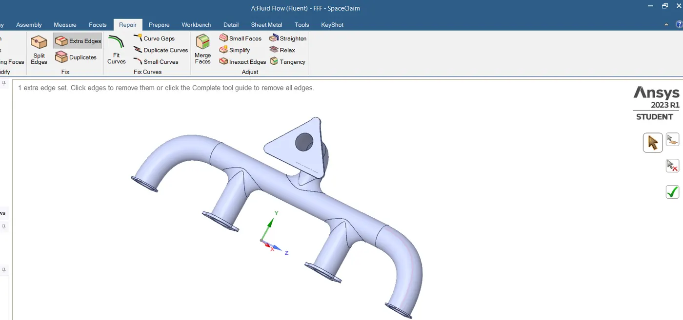
We need to delete extra/duplicated adges present in the goemetry.
Repair - Extra Edges
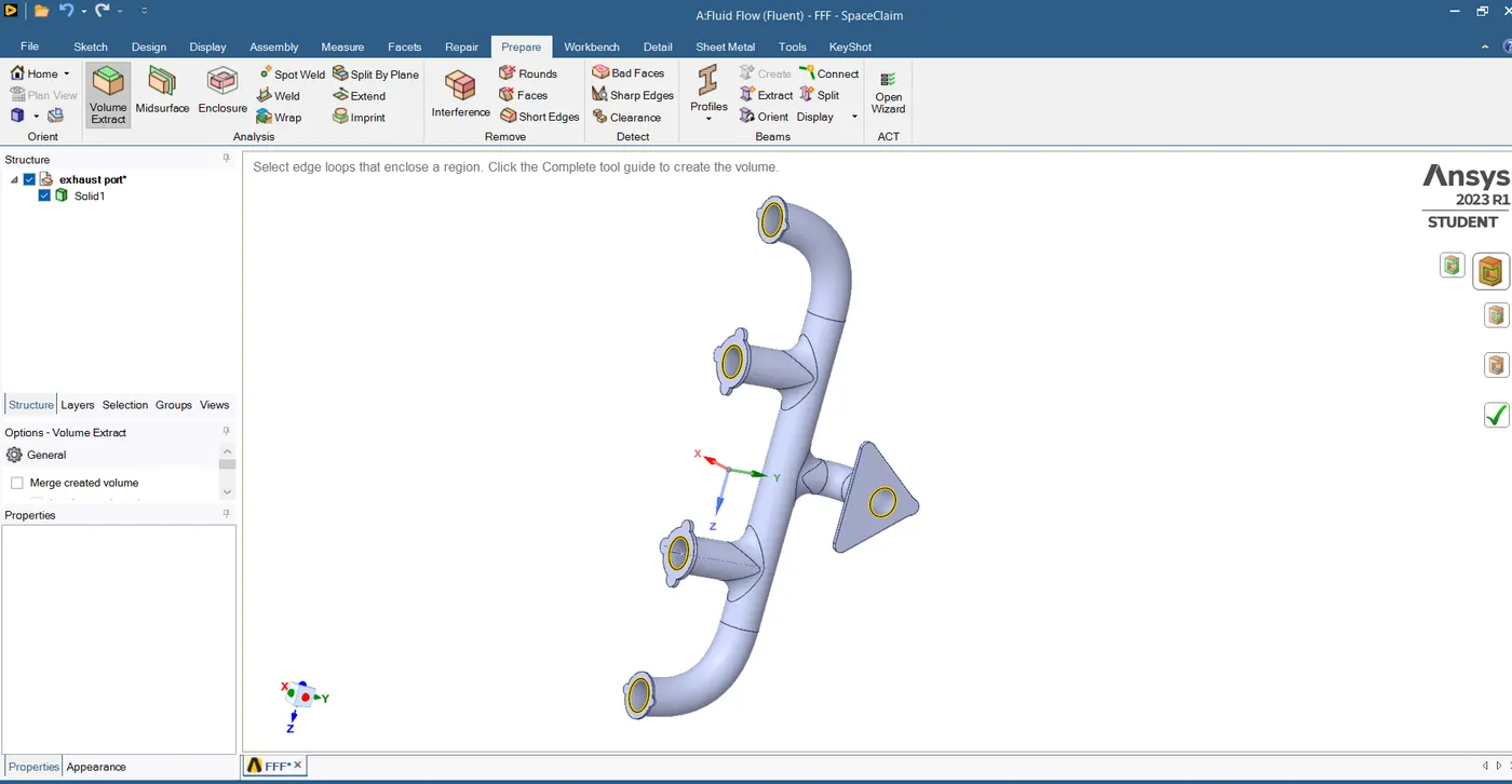
Extract the fluid volume.
Prepare -Volume Extract - Edge Selection
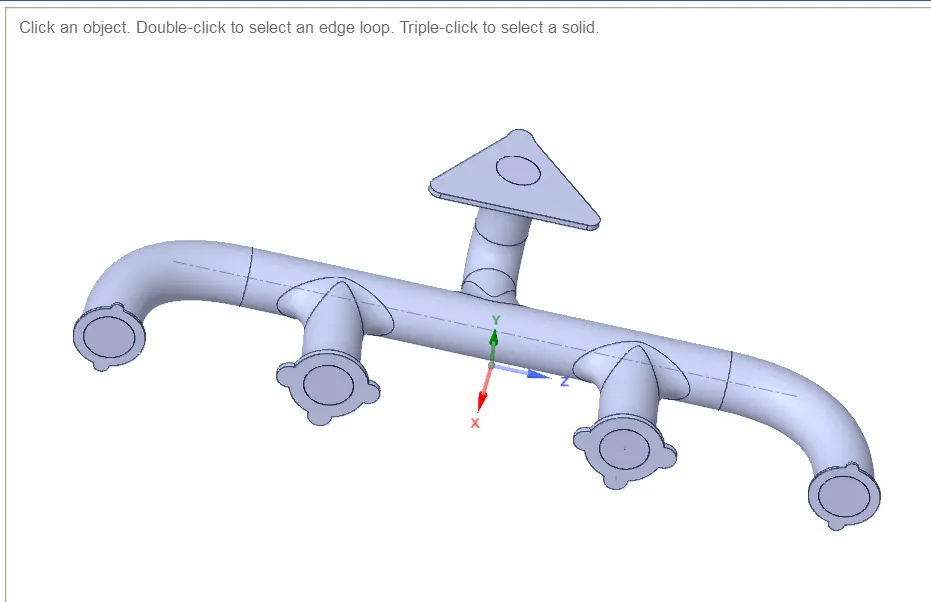
Giving names - Solid and Fluid Volume
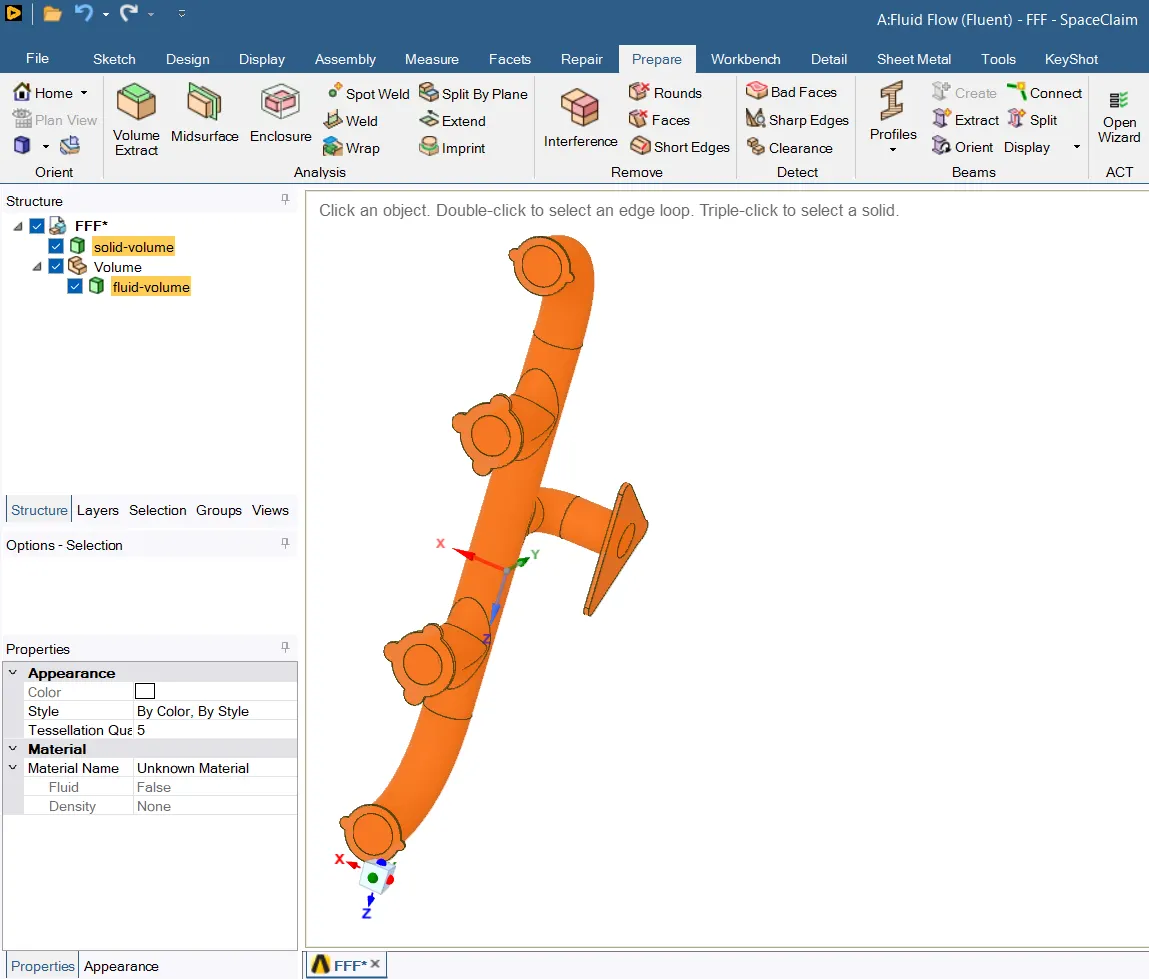
to fix the non-conformal mesh
We need both volumes under the same component,
Move to new component,Delete empty components.
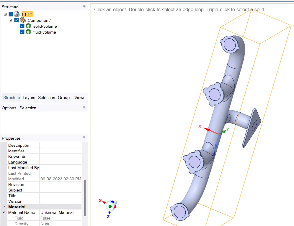
Workbench - Share
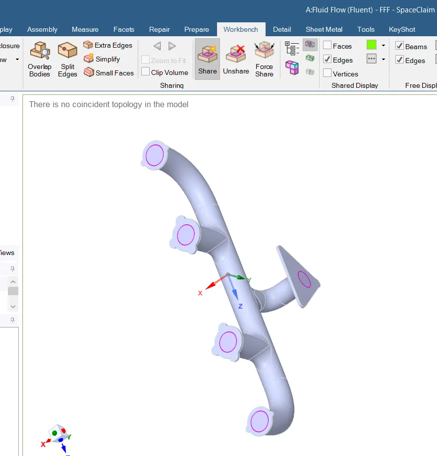
Pink Circles tells, where the faces are being shared.
Geometry Setup is complete
Mesh Setup
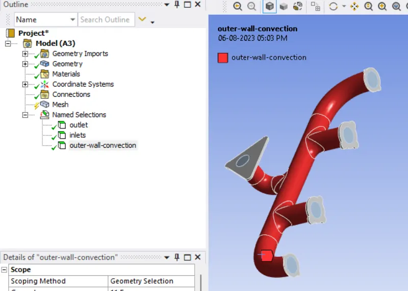
Creating Named Selection
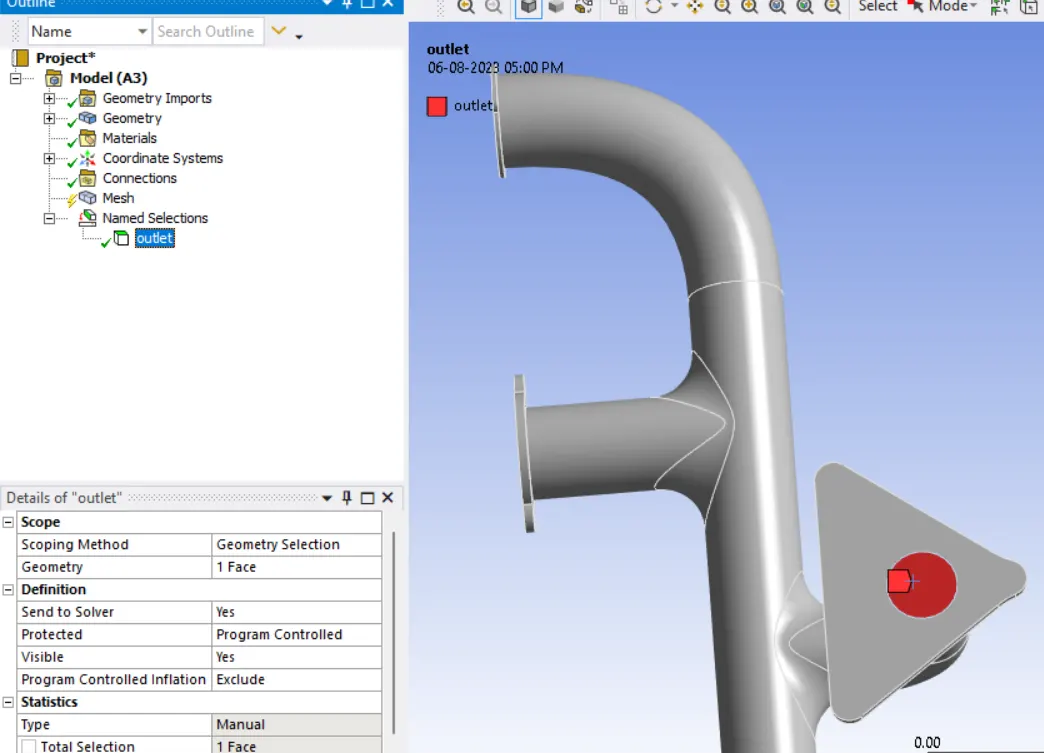
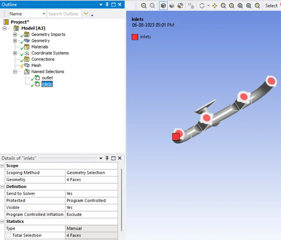
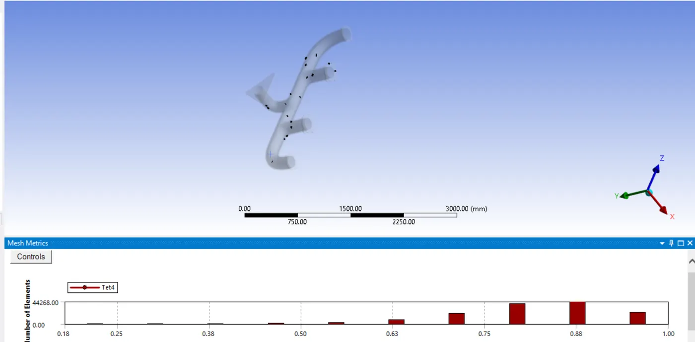
Generate Mesh
we want minimum 10% of Mesh Quality, Here it is around 21%
Fluent Setup
Pressure Based, Steady State Analysis
Energy Equation -On , Turbulence Model K-epsilon moedel
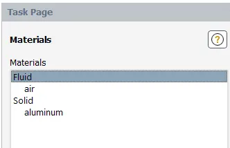
Materials - Air as Fluid and Aluminium as Solid
Boundry Conditions
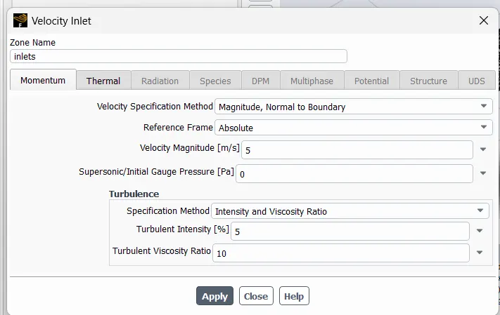
Inlet Conditions - Velocity-Inlet
Velocity - 5 m/s , Temperature - 700K
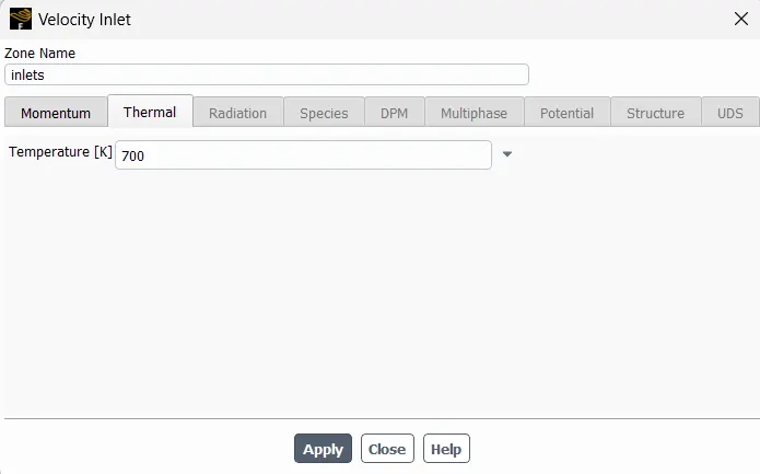
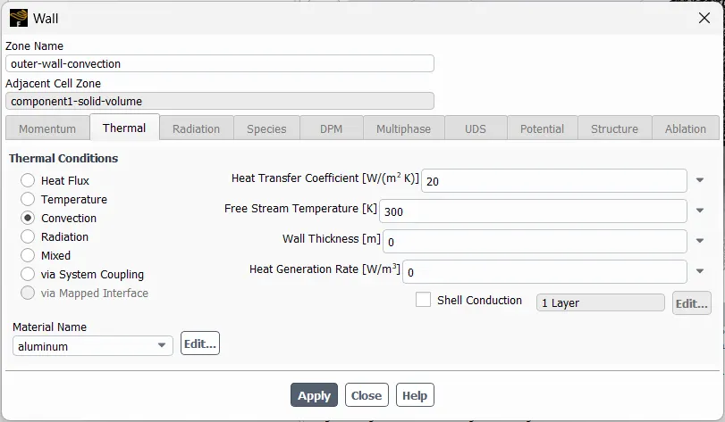
Outer Wall Convection
Convective Heat Transfer Coefficeint - 20 W/m^2 K ( Value found from experimental data)
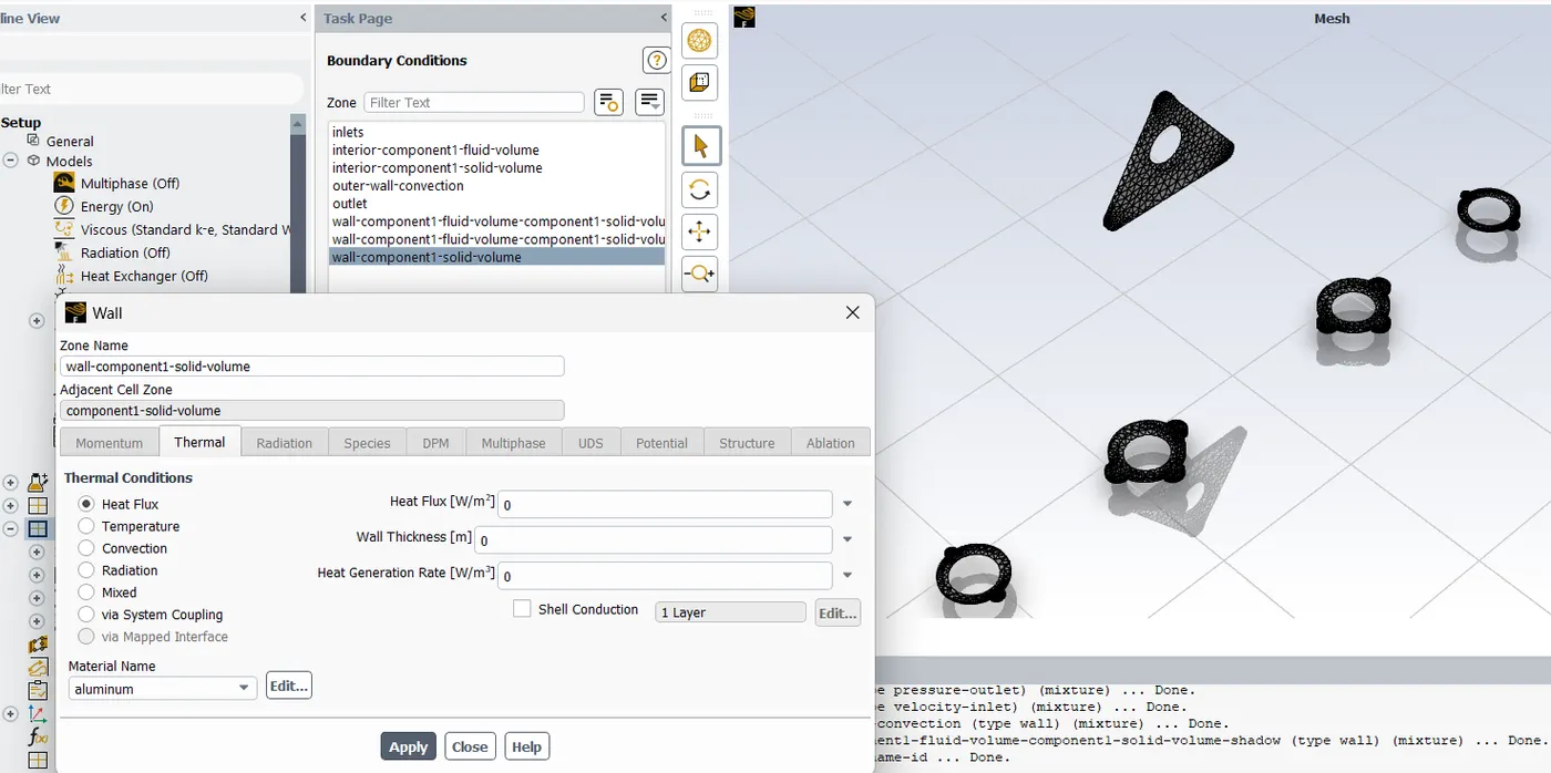
We want Heat Flux at some walls to be zero ( as they do not partiicpate in heat transfer - i.e. Adiabatic Heat Transfer)
Hybrid Initialization is done
Post Processing Contour Plots
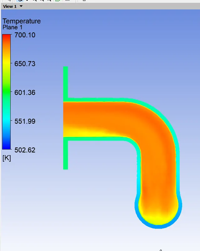
Temperature Countours
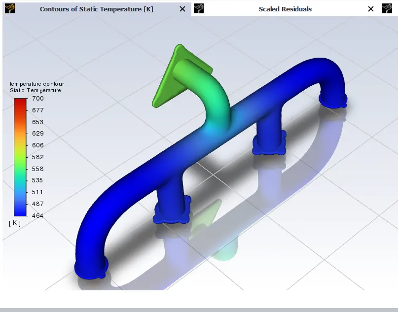
the wall/surface heat transfer coefficient on the internal solid surface
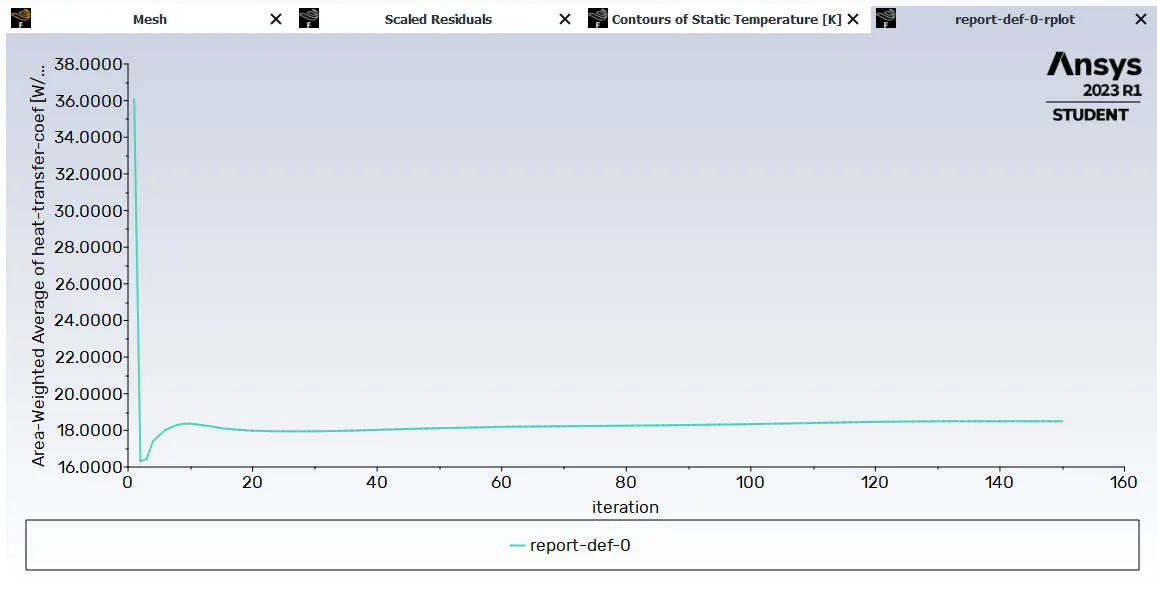
Surface heat transfer coefficient - 18.498069 [W/(m^2 K)]
CFD Post
Setting up Outer Wall Convection as variable of Temperature
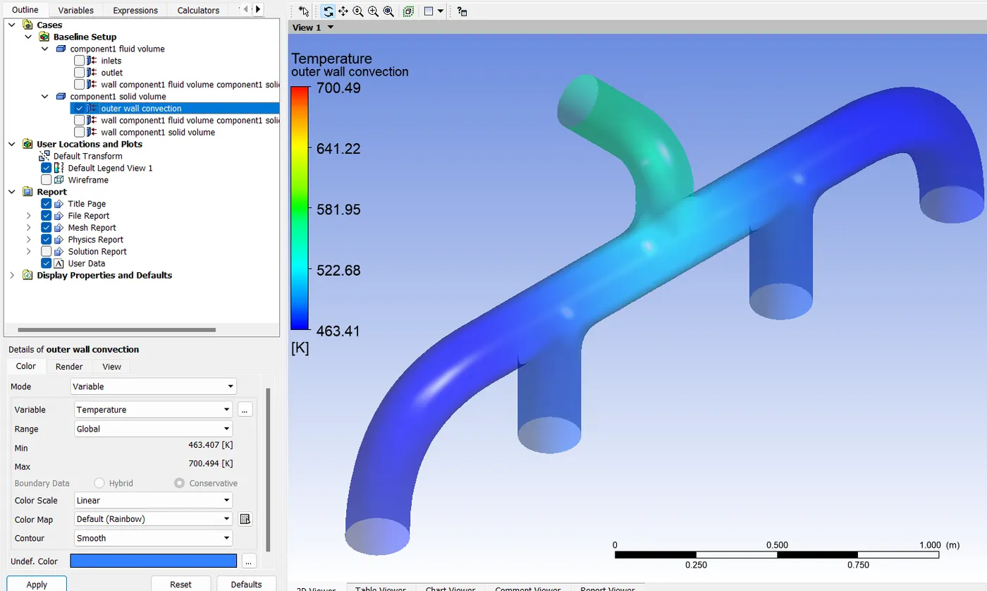
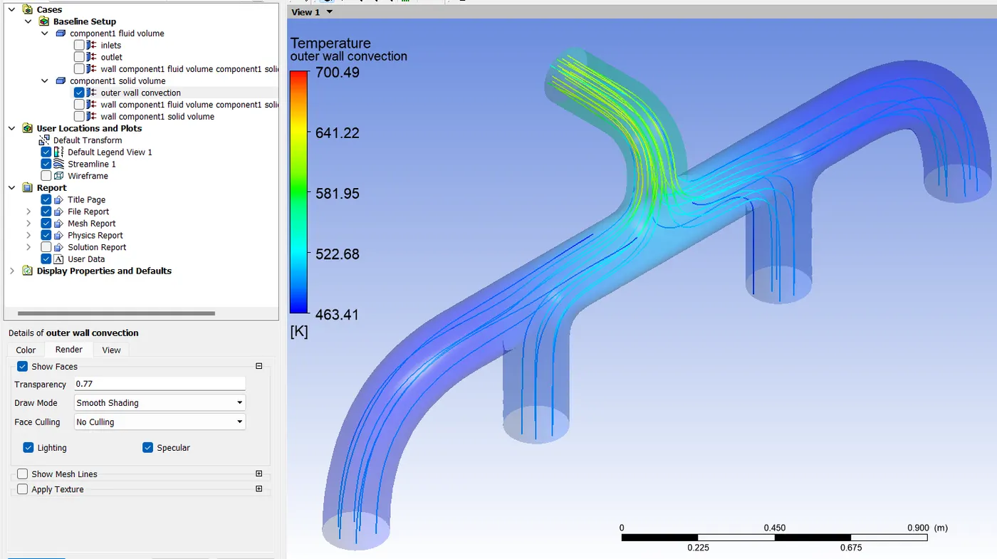
Inserting Streamlines
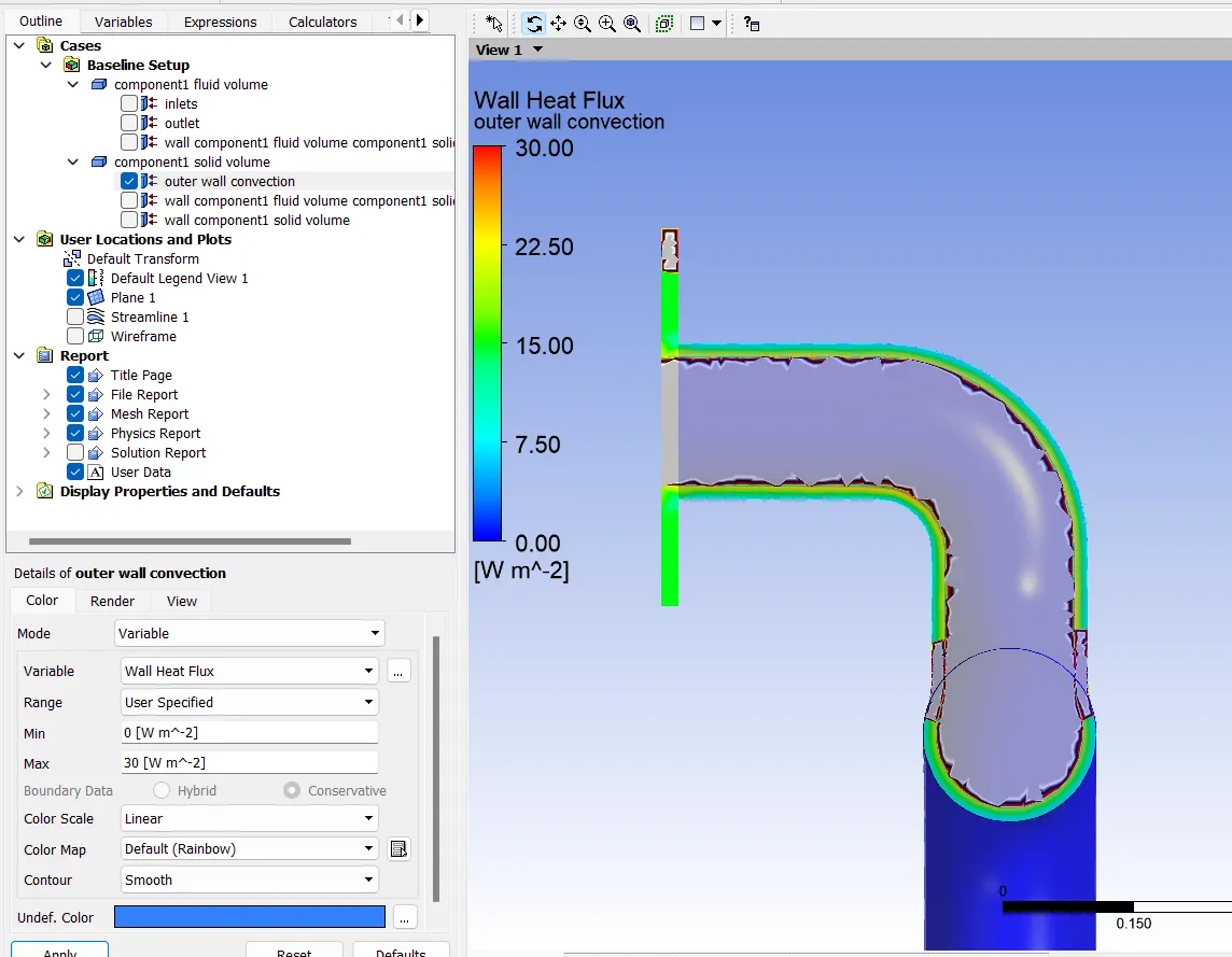
Wall Heat Flux
REFINED CASE -1
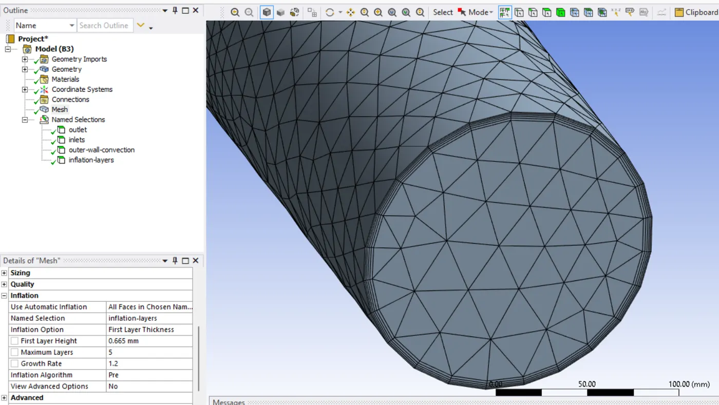
Adding Inflation Layer to mesh
Maintain the y+ value according to the turbulence model
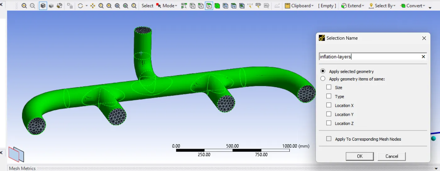
Creating Named Selection for Inflation Layers
Y+ Calculation using Online VOLUPE Software
- Average Temperature occuring at exhaust manifold = 500k
- Density of Air at 500 Kelvin Temperature = 0.705 kg/m^3
- Free Stream Velocity = 5 m/s
- Internal Flow Simulation '
- Desired Y+ Value is 5
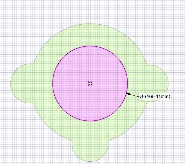
- Characteristic Length ( Average Dia. of Pipes) = 0.166 m
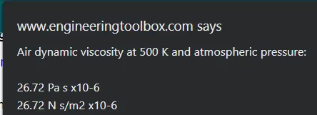
- Dynamic viscosity μ = 26.72 * 10^-6 at 500 K
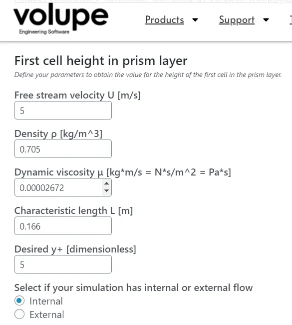
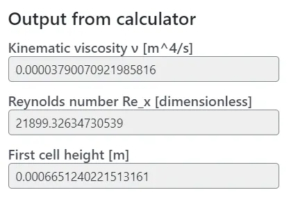
First Layer Thickness = 0.665 mm
Inflation Layers are created
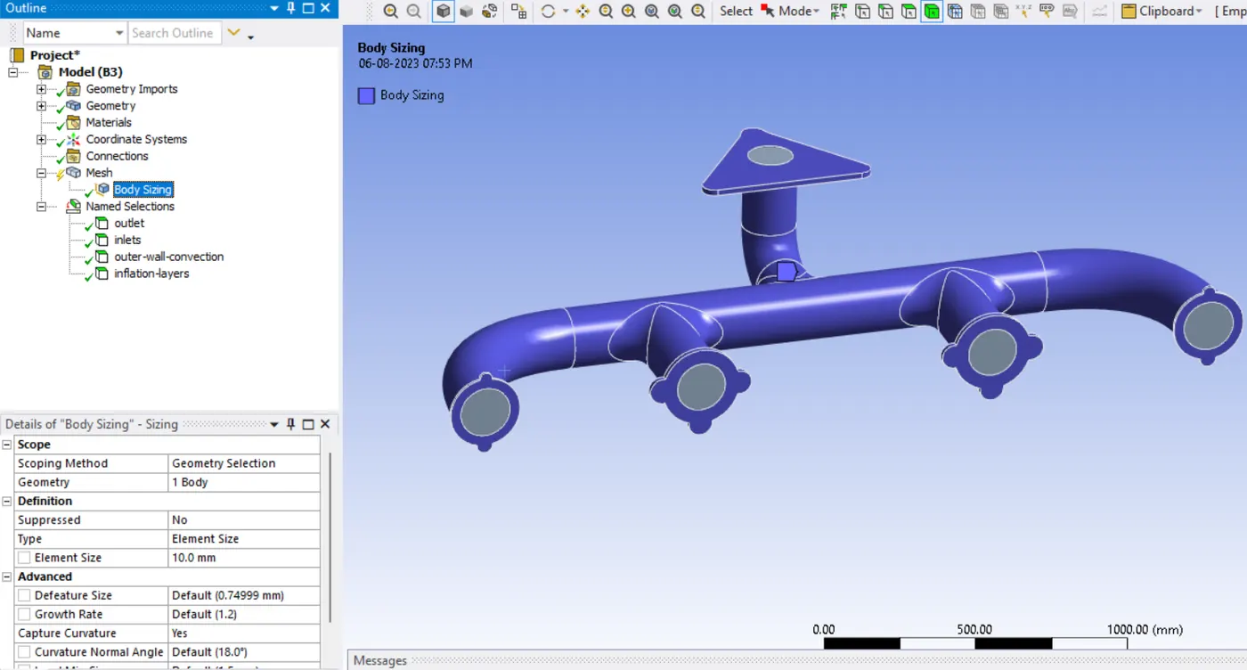
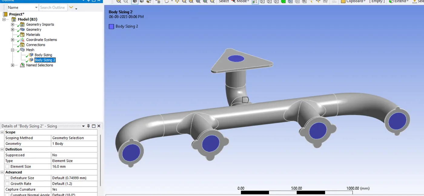
Insert - Body Sizing of 10mm for solid body and 16mm for fluid body.

Heat Transfer Coefficient
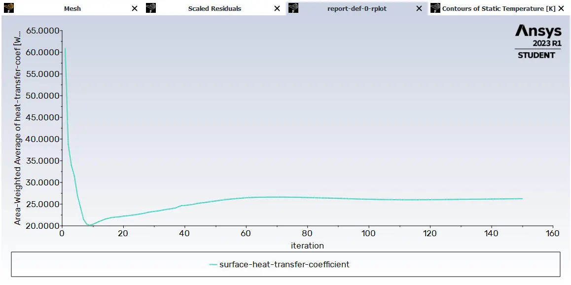
surface-heat-transfer-coefficient = 26.265011 [W/(m^2 K)]
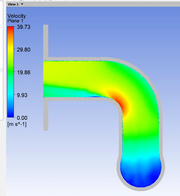
Contours of Velocity
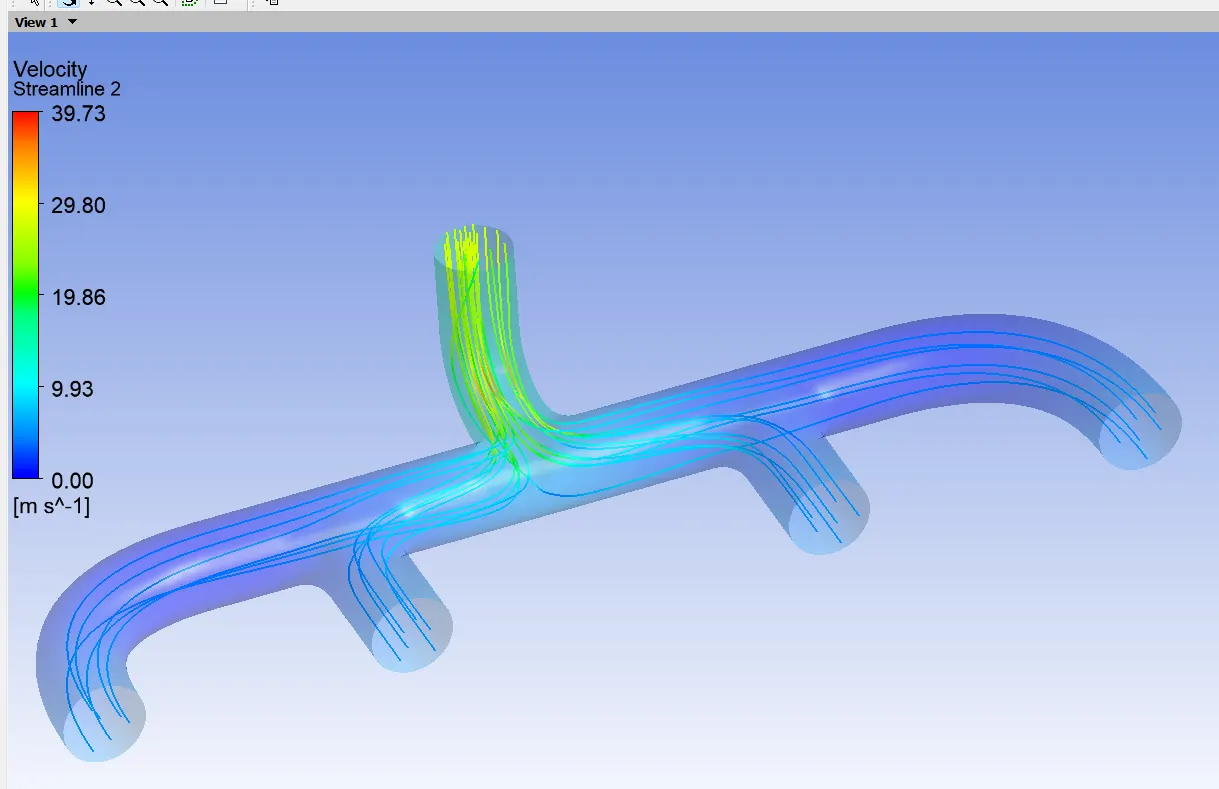
Velocity Streamline
Velocity Contours
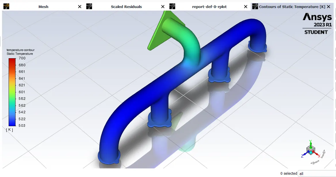
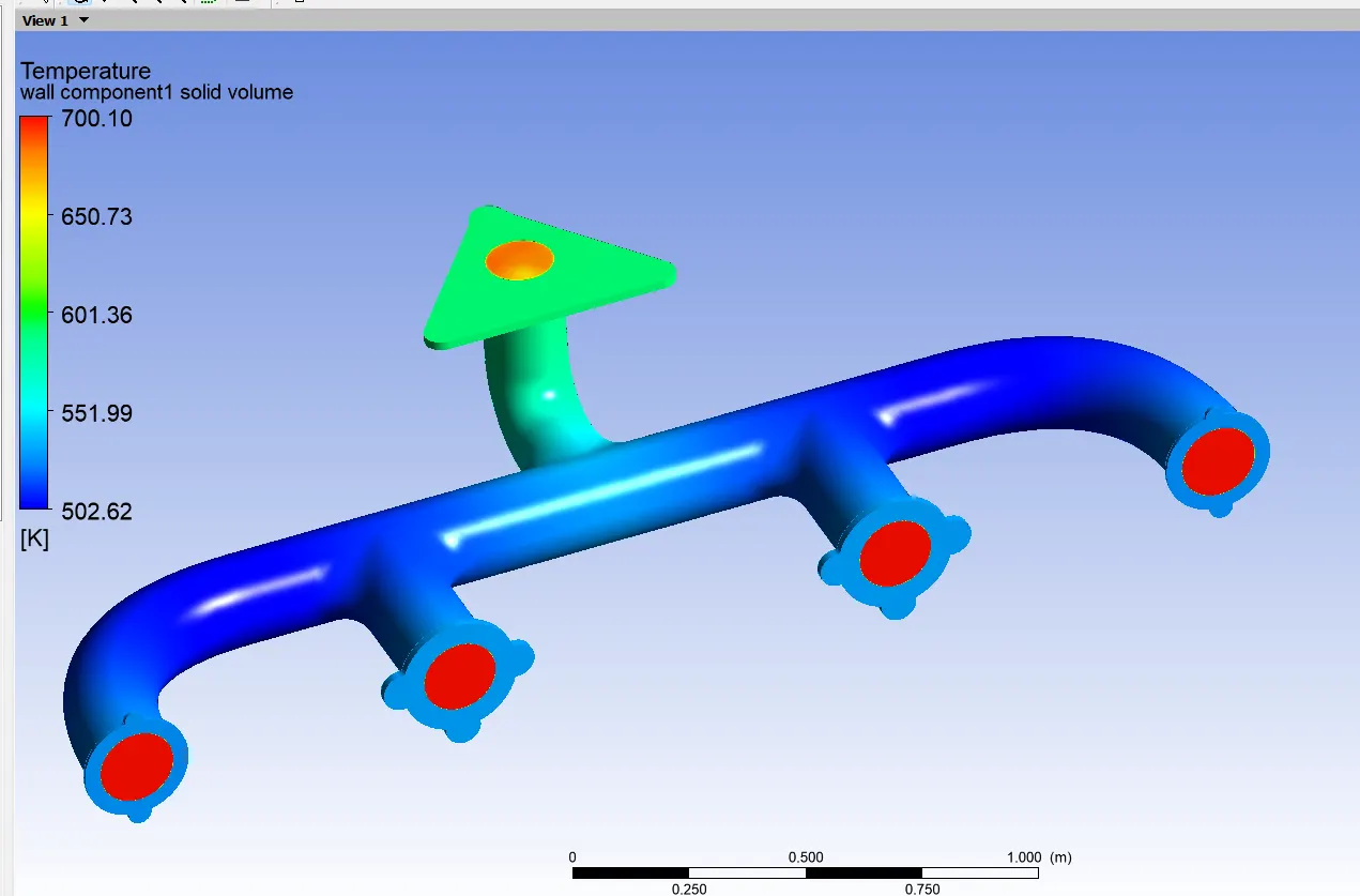
Temperature Contours
4. we need to verify if the HTC predictions from the simulations are right
we must calculate theorotical value of Wall Heat Transfer Coefficient
we are taking a help of Dimensionless Number,
Nusselt Number
Nusselt number is equal to the dimensionless temperature gradient at the surface, and it provides a measure of the convection heat transfer occurring at the surface.
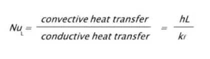
Nusselt Number is a function of Reynolds Number and Prandtl Number.
Re = ρ* V* L *μ
Taking Average properties of air
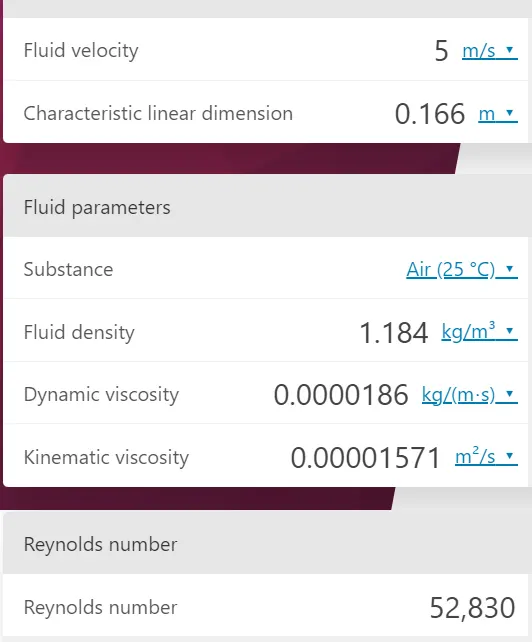
Reynold's No = 52,830
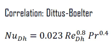
Correlation between three numbers is given as,
Pr = μ cp / k
cp of air - 1.031 KJ/kg *K
k = 0.0242 W/m-K.
Pr = 0.00002672 * 1.031 *10^3 / 0.0242 = 1.14
NU = 0.023 *(52830)^0.8 *(1.14)^0.4
NU = = h *L / k
145.4769761* 0.0242 / 0.166 = h = 21.20808929 W/(m^2 K
Here,
Theorotical Value = h th = 21.20808929 W/(m^2 K
Analytical Value = h a = 26.265011 W/(m^2 K)
This is how both the values are valiated.
Factors influencing the accuracy of HTC predictions:
-
Grid Resolution: The grid resolution directly affects the accuracy of the simulation. A coarse grid might not capture small-scale flow and temperature gradients accurately, leading to less reliable HTC predictions.
-
Boundary Conditions: Accurate specification of boundary conditions, such as inlet velocities, temperatures, and wall boundary conditions, is crucial for reliable predictions.
-
Turbulence Modeling: The choice of turbulence model significantly impacts the prediction accuracy. Using the appropriate turbulence model for the specific flow regime is important.
-
Fluid Properties: Accurate specification of fluid properties (e.g., viscosity, thermal conductivity) is essential for reliable heat transfer predictions.
-
Physical Assumptions: Assumptions made during the simulation, such as neglecting radiation or considering steady-state conditions, can affect the accuracy of the results.
-
Geometry Simplifications: Overly simplified geometries may not capture all the relevant flow features, leading to less accurate predictions.
-
Numerical Solver Settings: The choice of numerical solver and convergence criteria can affect the accuracy of the simulation results.
Overall, validating and verifying HTC predictions require careful consideration of these factors and a systematic approach to ensure the accuracy and reliability of the simulation results.