Week 4 - CHT Analysis on Exhaust port
Objective: To simulate and study conjugate heat transfer analysis in the exhaust port.
Theory:
Heat transfer is the phenomenon in which heat is transferred by virtue of temperature difference. This heat transfer is carried out in majorly 3 modes,i.e conduction, convection and radiation. In solids conduction is more dominant. The heat transfer happens due to vibrational motion of molecules/atoms. Convection happens predominantly in liquids. This happens due to bulk motion of fluid. It is not like that conduction won’t happen in liquids.At start conduction will be dominant but as the temperature difference is attained then due to this currents will be generated and convection will take place. So we can tell the phenomena by which heat is transferred in fluid is due to advection ,i.e conduction facilitated through the bulk motion of fluid. Convection on its own cannot happen,conduction is necessary for it to happen.
In the exhaust pipe,the inlet temperature of the air is very high and it flows with some velocity.As it flows through the pipe the walls of the pipe which are in direct contact with the flowing fluid heats up the walls.This heating of the internal wall happens due to the conduction.
Whatever heat transfer happens between the walls of the pipe from internal to external surface of the pipe is due to conduction. Now the outer wall of the pipe is in contact with the air, this air has some heat transfer coefficient so it cools the pipe by convection.
So in general the conjugate heat transfer problem consists of the body which is in contact with two different types of fluids on different sides of the body. So the heat transfer will happen from both sides ; to the body and from the body.
Here in case of exhaust pipes, the fluid on both the internal and external side is air but with different temperatures.
Geometry:
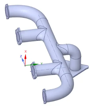
The geometry is loaded in the spaceclaim, this needs to be cleaned up.Every geometry which is made in cad is not made for simulation purpose. There can be some areas where extra edges or curves might still remain. So that needs to be removed. The cleaning of the cad is done in spaceclaim.
Also the geometry is divided in such a way that fluid volume and solid wall are separated from each other. Here the fluid volume and solid volume are separated . There are areas where this volume are shared. So when meshing is to be done, the boundary between this 2 volume should be shared uniformly. So here topology should be shared ,this inturn prepares the geometry for conformal meshing.
Meshing:
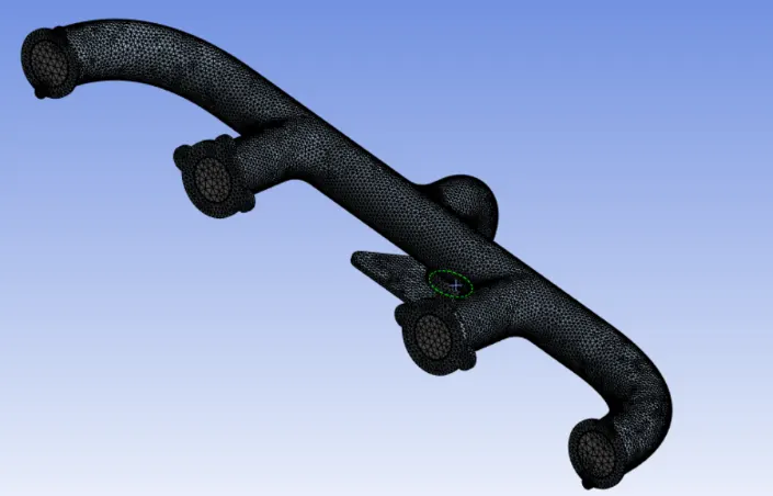
When the geometry loads up for meshing the first thing is to give a named selection. So select the 4 circular faces and right click on it and provide name selection as inlet.Similarly do it for outlet. Select the outer wall of the pipe and give it a name as outlet wall- convective. Generate the mesh,so that we get how the mesh behaves. The hot fluid is flowing through the exhaust ports. And due to this there will be heat transfer happening at the walls of the pipe. To capture the flow effects and temperature effects the mesh near the wall should be refined. For this inflation layer is added. Inflation layer is added for the fluid volume.
Also the mesh of the body is refined by using body sizing method. The total number of cells are:257506 and total number of nodes are: 82238.
Setup:
After the meshing is done , setup the case in Fluent. Here we will be using the k-omega model because we want to capture the flow phenomenon near the walls of the exhaust pipe. Also we will be solving the energy equation alonwith continuity and momentum equation, so select the energy tab.
The inlet boundary condition is velocity equal to 5m/s and temperature of fluid at inlet is 700 K.The boundary condition given for walls of the exhaust port is pure convection, so here value of heat transfer coefficient is specified which is 20 W/m2-K. The outlet boundary condition is given as gauge pressure 0 and temperature of 300 K.
The material of the pipe is Aluminium and the fluid flowing inside the pipe is air, so select this material from fluent library.
Before running the calculation make sure that you create contour for temperature so that we are able to visualize the temperature variation.
After the setup is done, initialize the problem and run the calculations for 600 iterations.
Post Processing:
From the streamline we can see that velocity at the exit is more as compared to inlet. This is because of mass conservation. Here area is same for both inlet and outlet, therefore to conserve the mass the velocity at outlet needs to be more. This can be seen in below figure.
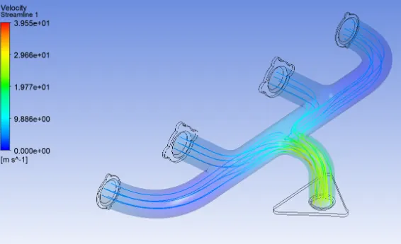
Now due to high velocity at outlet the Reynolds number will also be more. So we know from Nusselt number correlation , it is dependent on Prandlt and Reynolds number. So high Re means high Nusselt number , and which in turn signifies high heat transfer coefficient.