Week 4 - CHT Analysis on Exhaust port
- Give a brief description of why and where a CHT analysis is used.
- Maintain the y+ value according to the turbulence model and justify the results.
- Calculate the wall/surface heat transfer coefficient on the internal solid surface & show the velocity & temperature contours in appropriate areas.
- How would you verify if the HTC predictions from the simulations are right? On what factors does the accuracy of the prediction depend?
PROCEDURE
THE PURPOSE OF CONJUGATE HEAT TRANSFER ANALYSIS IS TO VARIOUS TEMPERATURES CONCERNING SOLIDS AND FLUIDS, DUE TO THERMAL INTERACTION BETWEEN THEM LIKE HEATING WATER IN A PAN OR HEAT TRANSFER FROM THE ENGINE TO THE RADIATOR AND RADIATOR TO ATMOSPHERIC AIR.
STEPS TO BE FOLLOWED
Step 1: Initially, start with importing the geometry to the Ansys workbench
If you check the geometry it has solid volume so we need to extract the fluid volume by following prepare -> volume extract -> select edge selection -> then select all the edges (inlet and outlet ).
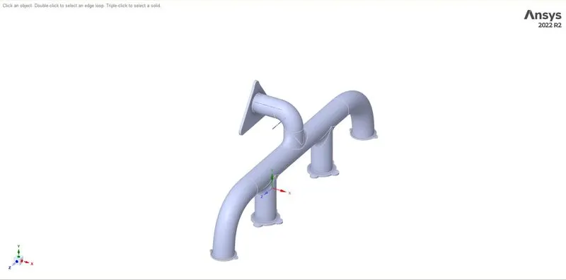
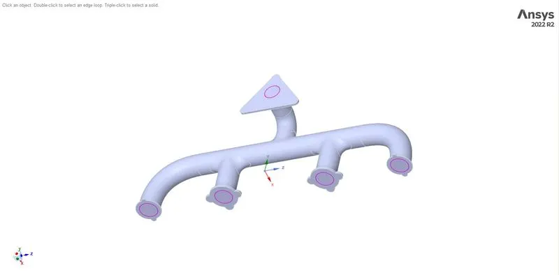
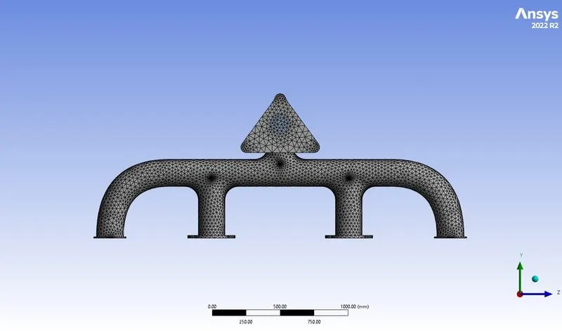
Step 2: From the geometry create two kinds of mesh (coarse mesh and fine mesh) to perform grid independent study
1 coarse mesh
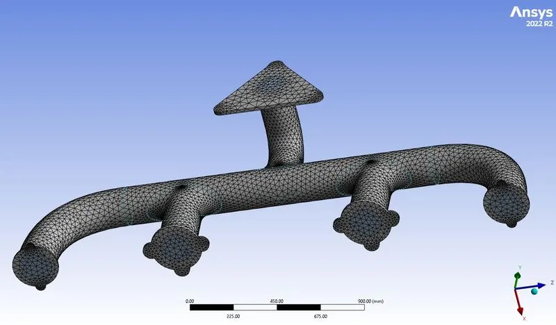
2 Fine mesh
The fine mesh has been created with an inflation layer according to the turbulence model and refined the mesh size of fluid volume has to get a more accurate result
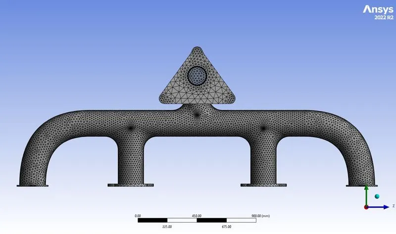
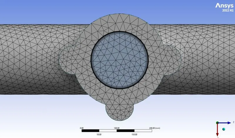
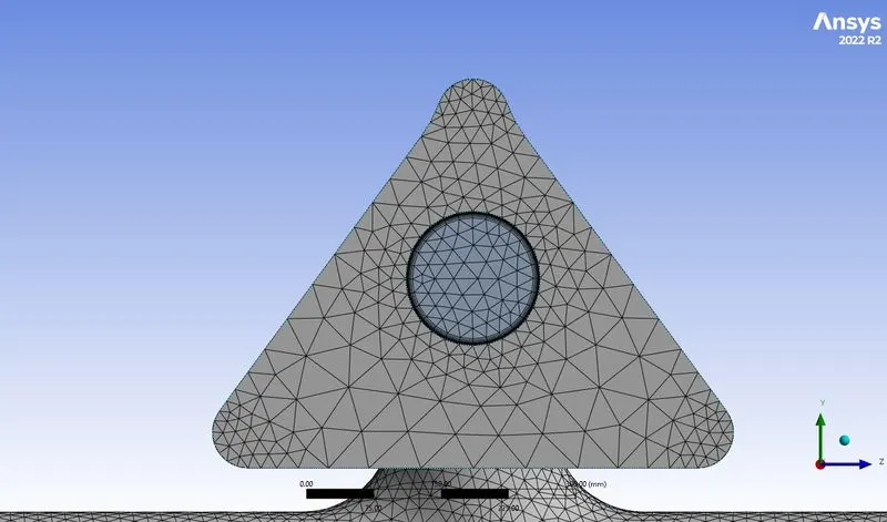
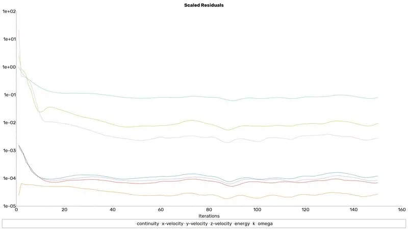
After generating the mesh, the number of nodes and elements is investigated using the statistics option. Then the mesh quality is checked by choosing the mesh matrices option in the quality section.
Step 3:In this step, the meshed geometric file has been imported to the fluent module and set the following conditions as follows in the fluent in solving the problem.
This procedure is followed in Ansys fluent
|
SOLVER TYPE |
Pressure based |
|
VELOCITY FORMULATION |
Absolute |
|
TIME |
Steady |
|
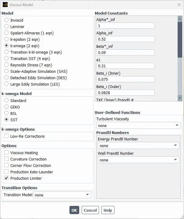
VISCOUS MODEL |
K-omega SST model and enable energy equation to solve the energy equation |
|
MATERIAL |
Fluid: air Solid: aluminium |
|
CELL ZONES |
Fluid flow region: air Solid region: Aluminium |
|
BOUNDARIES (depends on the momentum ratio) |
Inlet (velocity inlet)=5m/s Temperature=700k Outlet(pressure outlet) Internal solid wall=wall Outer wall=wall convection 20 `w/(m^2k)` |
|
Report definition |
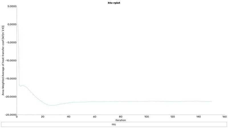
Area weighted average wall flex Surface heat transfer coefficient on the internal pipe wall |
the hybrid scheme is used for the initialization


Results for coarse mesh
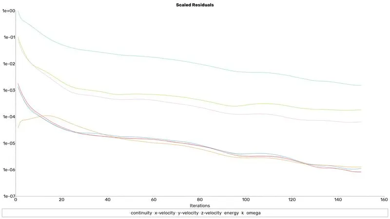
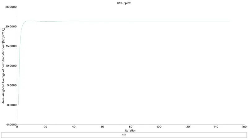
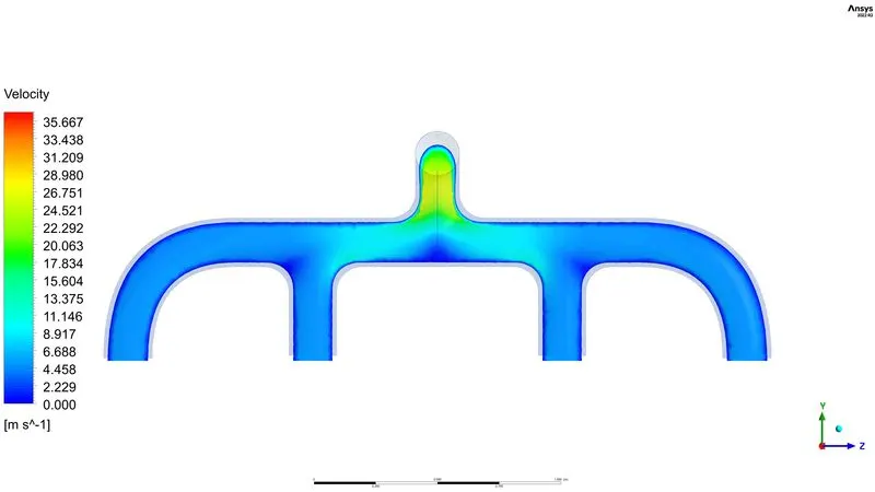
contour plots
Velocity contour
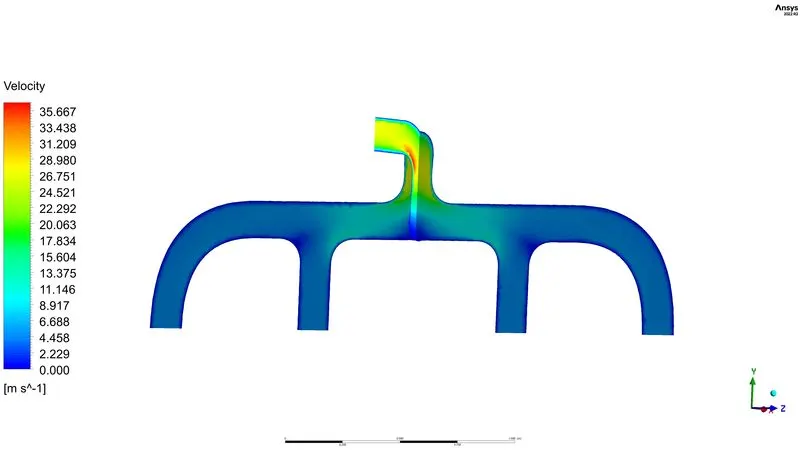
Temperature contour
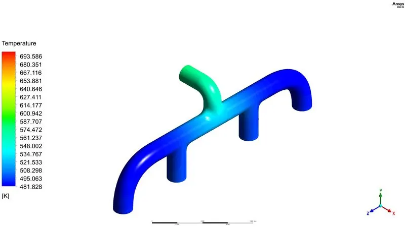
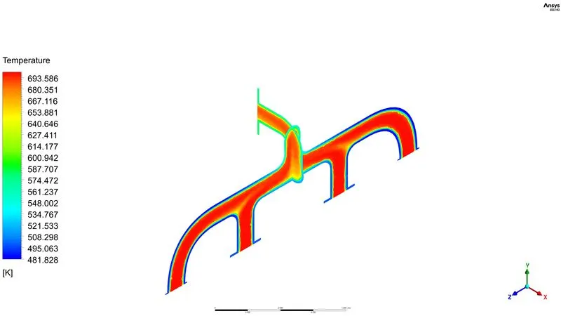
Streamline plot
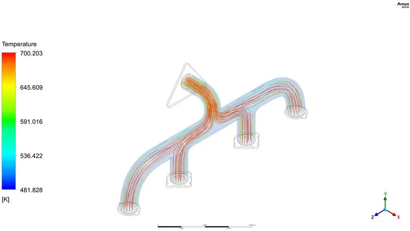
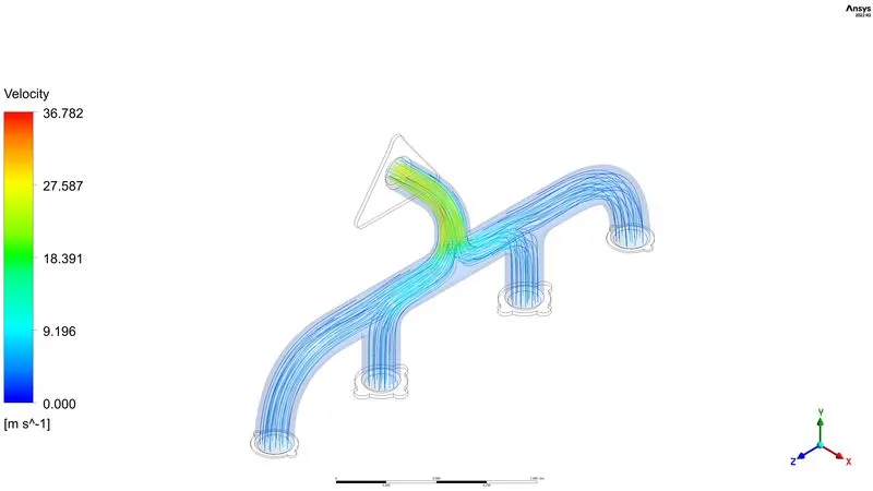
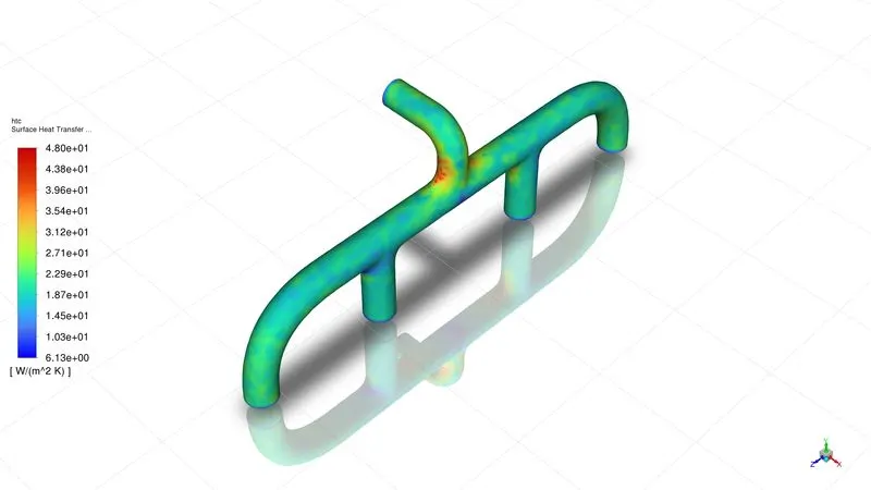
Heat transfer coefficient
Results for fine mesh
contour plots
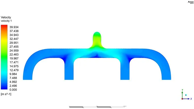
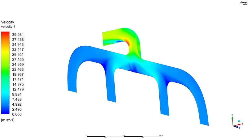
Velocity contour
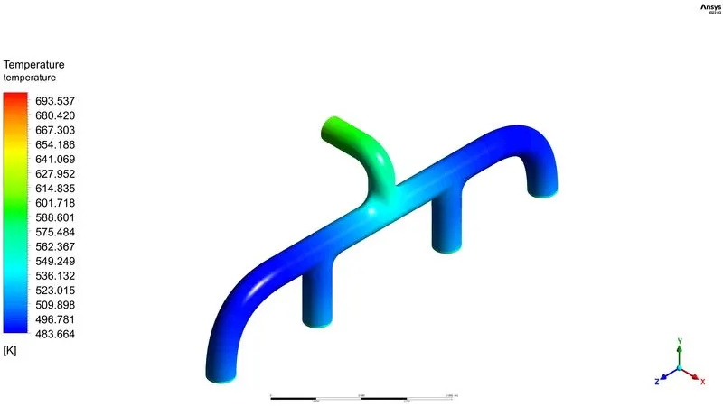
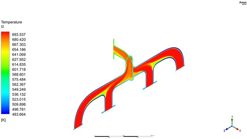
Temperature contour
Streamline plot
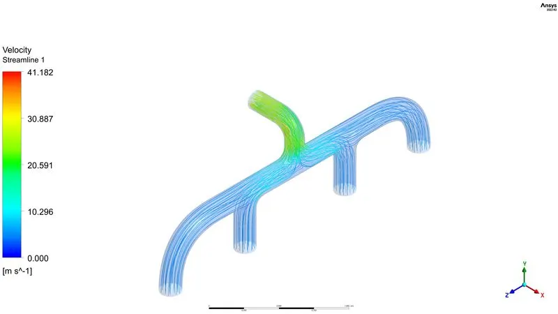
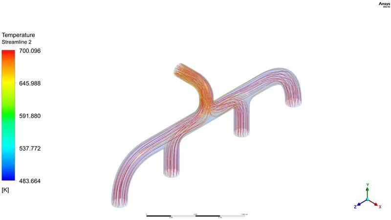
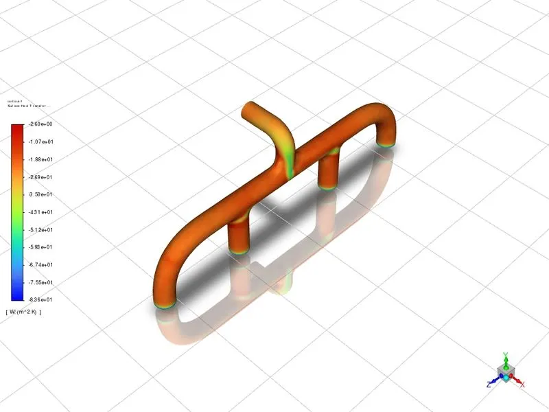
- By observing the velocity plot it will be apparent that velocity is maximum at the outlet than the inlet because the mass outlet is 4 times the mass of the inlet (due to 4 inlets and 1 outlet) and the contour shows velocity is varying while fluid is approaching from inlet pipe to outlet pipe.
- the heat transfer coefficient is high in the outlet pipe than in the inlet pipe, So that's the reason for the high temperature in the outlet pipe than in the inlet (the high surface temperature at the outlet happens because of the all pipe meeting together)
Verifying the HTC predictions
- According to Bernoulli’s principle in an incompressible flow mass entering the region is equal to the mass leaving the region in other words Bernoulli’s principle, states that the whole mechanical energy of the moving fluid, which includes the gravitational potential energy of elevation, fluid pressure energy, and kinetic energy of fluid motion, remains constant.
As mass is neither created nor destroyed, mass flow rates are also balanced
`Delta m_1+Delta m_2+ Delta m_3 +Delta m_4 =Delta m_(out)`
`Delta m=rho Av Deltat`
The mass flow will be calculated for unit time and the computed results are shown below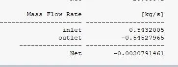
- The Nusselt number is the ratio of convective to conductive heat transfer across a boundary.
`Nu_L=" convective heat transfer"/"conductive heat transfer"=(hL)/k`
Nusselt number is related to the Reynolds number
`Nu=0.023 Re_D^(4/5) Pr^n`
`Re=(rho u l)/mu`From the above equation, it will be clear that heat transfer is directly proportional to the Reynolds number so by changing the velocity of fluid the heat transfer changes with respect to it.