Week 4 - CHT Analysis on Exhaust port
AIM: Simulation of conjugate heat transfer analysis over exhaust port.
Introduction:Here we deal with the exhaust port which have 4 or more inlet & only one outlet for the ehaust gas to flow out.we try to capture the heat flow through the walls of exhaust port & even velocity of exhaust gases through outlet.
Objective: The CHT analyis is always used between the solid & liquid domains,where there is a exchange of thermal energies between two interfaces.
- Theory:
Here the bascially we study the heat transfer of hot gas within the exhaust port ,it occurs because of conduction & convection of hot flu gases withb in the exhaust,this results will be observed at the walls of exhaust ports at outlet,out outlet there will be the maximum velocity & high temperature at the out let where fluid flows with high velocity. this type of heat transfer we can observe in battery cooling methods also & many more applications where heat transfer takes palce between two interfaces.
- Solving & Modelling approach :
- download the model from the source to complete the challange. than create the share topology with the model of solid volume & liquid volume.
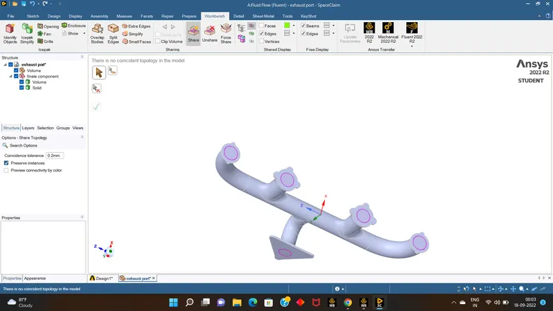
- Than go for Meshing part of the model,firstly do the meshing with random target lengths,than if any possible to refibne the mesh go with it.
- even go with infliation layer at the inlets of the port.
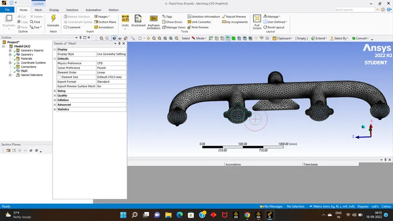
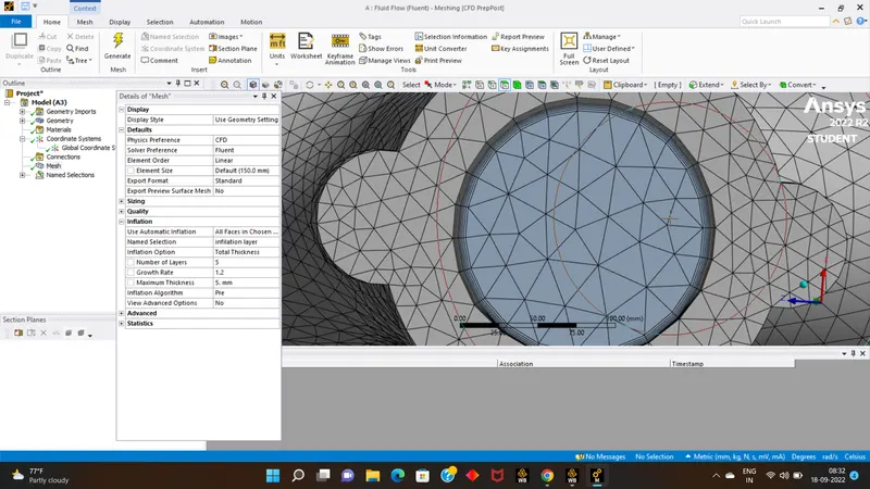
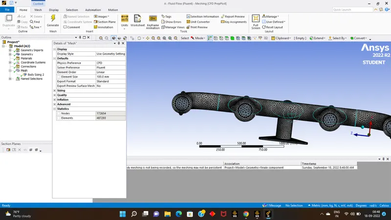
- now we are satisfied with the meshing, so we continue with nxt set up part.
- after seeing results if any changes are required than we can come back to meshing aand change the meshing.
- Pre-processing and solver setting:
- now we will enter into setup par.
- here we will see energy eqn, viscous model will be E-epsilon. materials used will be: fluid-air,solid-aluminium.
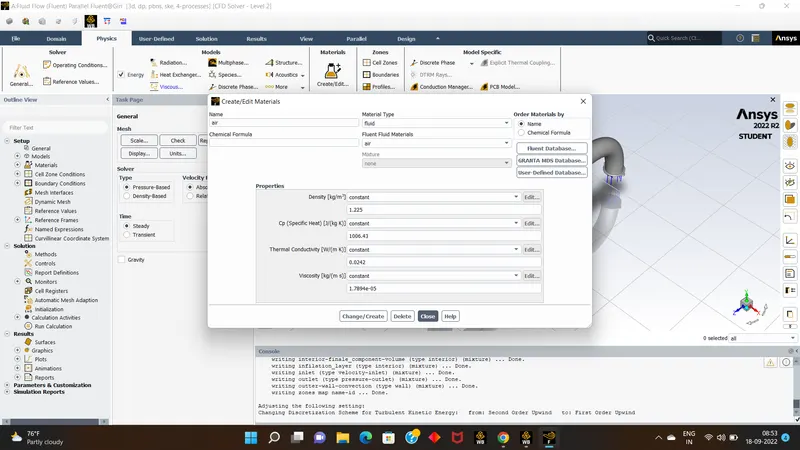
- Than go to boundries and set the inlet velocity as 5 m/s.& temperature as 700k.
- than for outter wall convection set the boundary condition for convection as 20wm/s.
- than initilaise the calculations,than set the contour for temperature, & even set the solution animations.
- than Run the calculations for 150 itriations,wait for results.
- Results:
- as we see the results & temperature contours obtained.
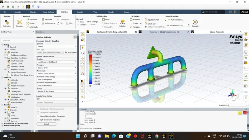
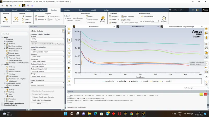
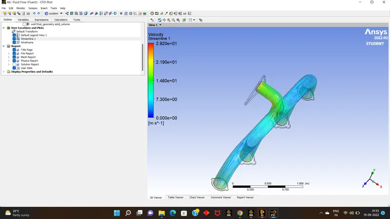
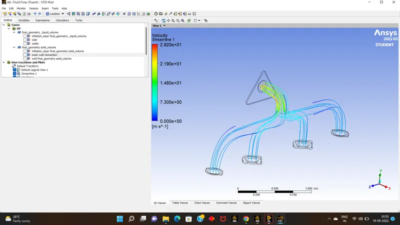
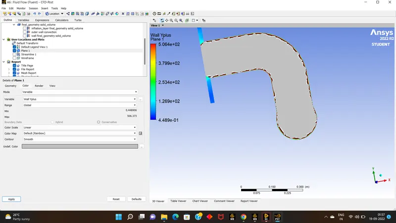
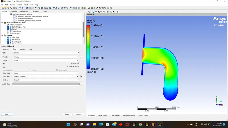
- we can see many results over an single simulation.
- Conclusion :
- from the results we can clearly say that the finer meshing yields good results.
- from the above picture we can say that where the velocity is more there is rise in temperature of exhaust gases.
- at the bottom bend of a plane we can see the high temp& high velocity exhaust gases .