Week 4 Challenge : CFD Meshing for BMW car
Week 4 Challenge : CFD Meshing for BMW car
Aim/Objective:
For the given CAD model of BMW M6 we will check and solve all geometrical errors on half portion and Assign appropriate PIDs. Perform meshing with the given Target length and element Quality criteria. After meshing the half model, Do symmetry to the other side.
Target lengths for the different parts of a model are as follow:
- Body - 3 mm
- Lights - 4 mm
- Grills - 1 mm
- Rims and Tyres - 2 mm
- Optical Rear view mirror - 2 mm
- Window - 2 mm
- Silencer - 3 mm
- Logo - 1 mm
Procedure:
We will be following 4 major steps
STEP 1: Geometry cleanup
STEP 2: PID assignment
STEP 3: Surface Meshing of BMW car
STEP 4: Computational Fluid Flow Domain creation and surface meshing of domain
Each step has a series of sub-steps to be followed, we shall be discussing in detail along with snapshots of the sequences wherever required.
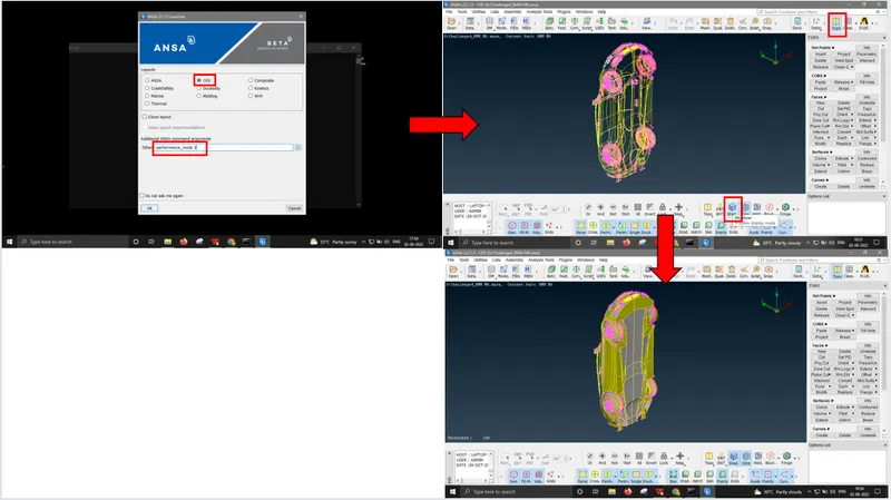
The first step is to open the ANSA in performance 3 mode with CFD enabled. Open the given CAD model of the BMW M6 from FILE > OPEN. Default view of the geometry is wireframe, we shall turn on SHADOW mode for better visibility.Let us start the geometry cleanup.
Since the resolution of the given model is low, we shall use MESH > LENGTH > PERIMETERS to 1 mm length to improve the resolution of the car model.
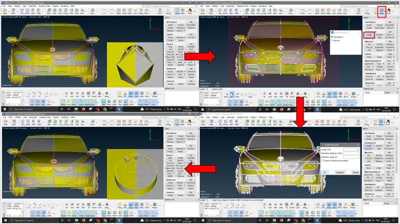
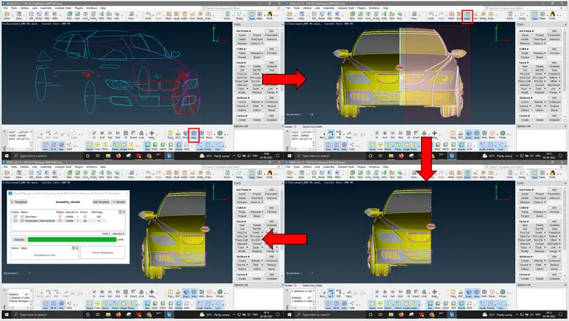
Approach of work: Since the BMW M6 is a symmetrical car along the length, we can delete half of it (except the logo)and work on the other half and copy it to the other side finally. We will start splitting the geometry and work in parts, like first we will finish geometry cleanup of grill, run check manager and assign PID. Similar manner we can complete the model.
STEP 1: Geometry cleanup
GEOMETRY CHECK: Let us start with a geometry check, under the TOOLS > CHECKS MANAGER > GEOMETRY select the geometry to run a geometry check along with the penetration check too. Click on the EXECUTE , it shows all the geometric and penetration errors.
In order to create a water tight model, we need to delete unnecessary volumes inside the fluid flowing region and close all openings. Since our area of interest is the volume outside of the BMW M6 car model, we can simply delete unnecessary volume inside the car model and make the car body as a single water tight model.
FRONT GRILL GEOMETRY CLEANUP:
Front grill area contains 3 grills for simplicity we can name it as grill 1, grill 2 and grill 3.
Grill 1:
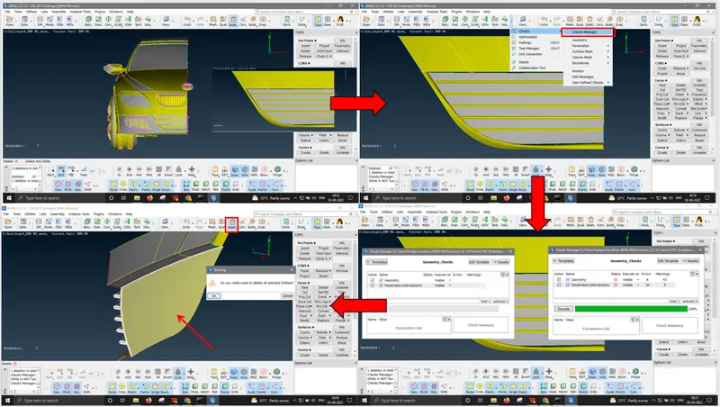
First we isolate the grill 1 from rest of the geometry using FOCUS tools and we will run geometry check from UTILITIES > CHECKS > CHECK MANAGER. So, we now know what to work on, there are unnecessary faces we can delete it.
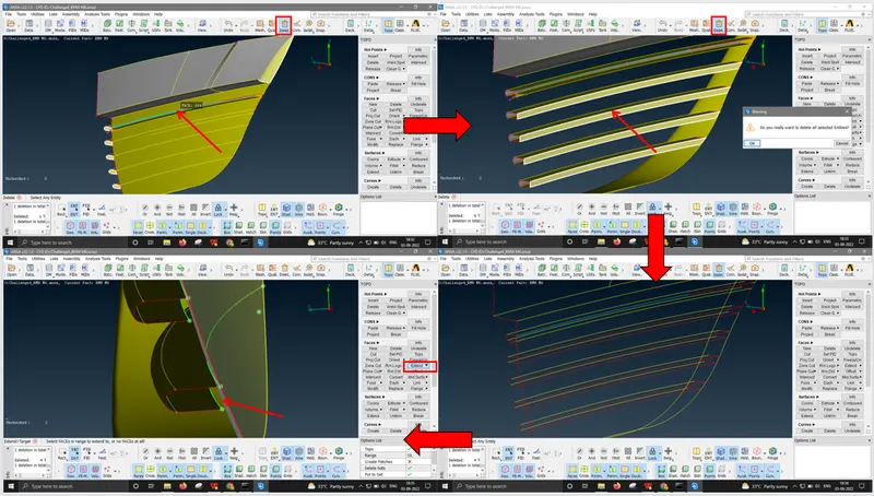
After deleting the unnecessary faces in the grill, we need to connect the grill surface to the closing surface at the inside. So, there are a couple of ways to do that. Either we can PROJECT the single CONS to the back face delete the grill bottom face and create a new face with the newly projected con, PROJECT the grill FACE to the back face, try to INTERSECT the grill face to back face or we can EXTEND the grill face to the back face and the side face to get a clean finish.
In this case we can use EXTEND option, select the single con in grill face middle mouse button and select the back face and do the same for the side face as well. Repeat the same for other grill faces too & delete the unnecessary faces that disrupts the water tight model concept (in this case the unwanted triple CONS).
Once the geometry cleanup is done in grill 1 region, we can run geometry checks again to confirm there is no error.
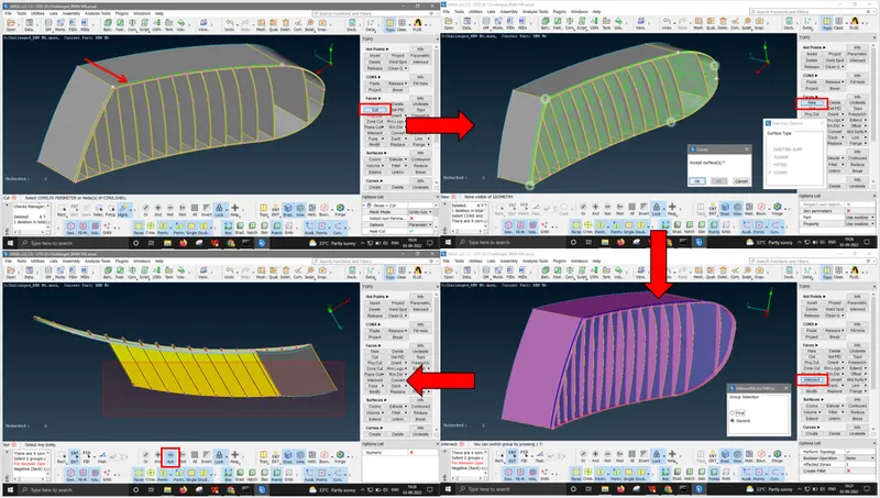
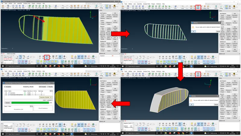
Grill 2:
First we isolate the grill 2 from rest of the geometry using FOCUS tools and we will run geometry check from UTILITIES > CHECKS > CHECK MANAGER.
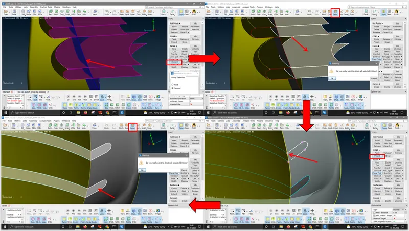
Let us delete unnecessary surfaces on the perimeter of the grill, there are 2 sets we will delete one set and retain another for us to use cut option. On close observation, there is a 0.1 mm mismatch on the interface of each grills left and right faces with the back face. So, inserting a hotpoint on the retained faces using HOTPOINT > PARAMETRIC in distance mode we can insert hotpoints at 0.5 mm or 1 mm closer to the back surface.
Now we can create a cut using FACES > CUT option around the grill, with which we can create a surface using FACES > NEW > COONS option. The idea is to use this newly formed plane as a cutting plane and simply delete unwanted portion of the geometry, that can be done using INTERSECT option. Using intersect and selecting the grills and the newly formed surface should do it. Then, we can manually orient the view to top view and box select to hide out needed surfaces, INVERT the view and box select DELETE unnecessary faces. The approach to geometry clean up is subjective, this method gives clean edges in the output.
Once the geometry cleanup is done in grill 2 region, we can run geometry checks again to confirm there is no error.
Grill 3:
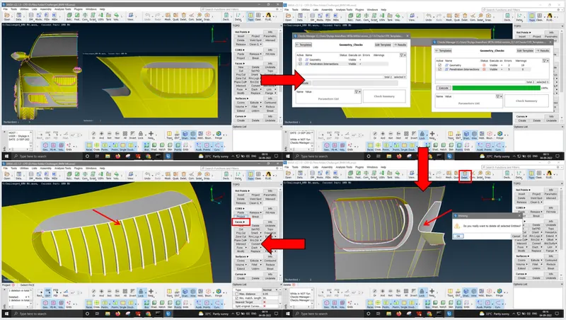
First we isolate the grill 3 from rest of the geometry using FOCUS tools and we will run geometry check from UTILITIES > CHECKS > CHECK MANAGER.
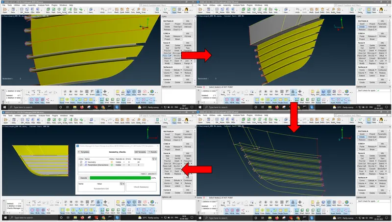
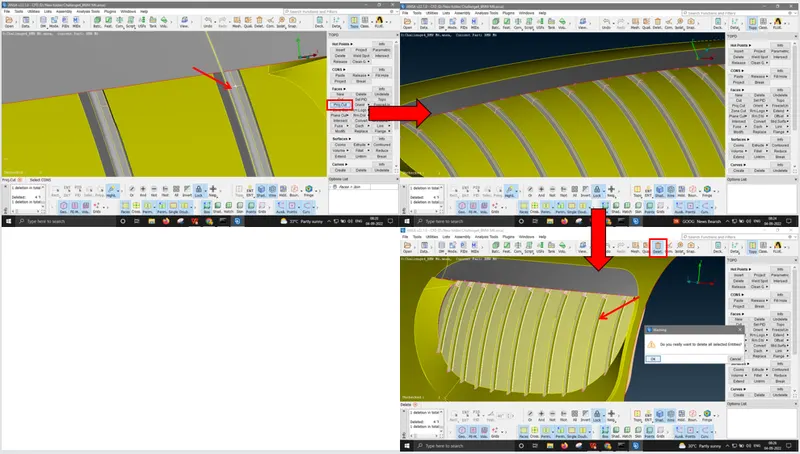
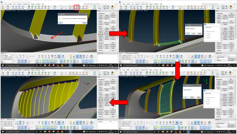
We will start geometry cleanup from deleting unwanted faces, resolve triple CONS. CONS > PROJECT the single CON to the middle surface of individual grill elements. Use PROJECT CUT option to cut along the side faces of each grill.
Now delete the upper portion of each grill that we just used PROJECT CUT and delete the back surface too using universal DELETE option.
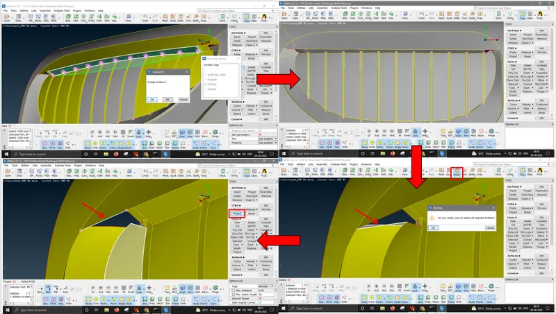
There are very sharp cuts at the bottom of each grill faces, we can use PROJECT CUT to cut perpendicular from the hotpoint and DELETE the sharp face along with the bottom face between each grill.
Create a FACES > NEW > COONS at the space between 2 grills and the surface we created newly at the bottom portion. In a same manner, close all the gaps between and the bottom part of grill to grill.
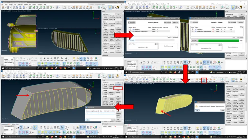
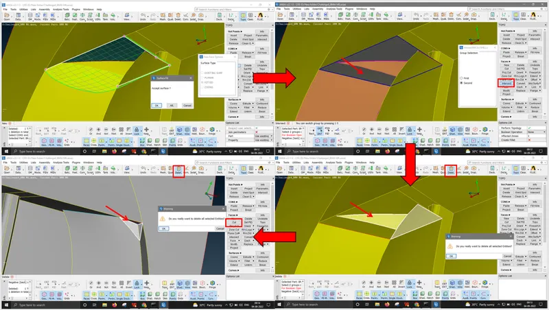
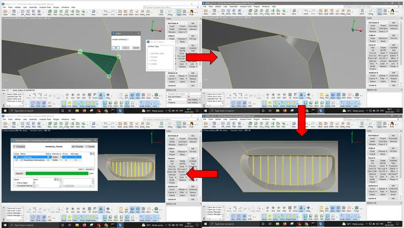
We can use FACES > NEW > FITTED with loop enabled to close the top side gap between the front surface and the grills. For the gap at the intersection of the front outline contour and the grills, we will create a new surface there. Using INTERSECT option, intersect the contour surface and DELETE the unwanted faces. For the front side, there a small triangular surface , we will delete that by making a new CUT and create a new surface there using FACES > NEW > COONS. And repeat the same to the other side as well.
Once the geometry cleanup is done in grill 3 region, we can run geometry checks again to confirm there is no error.
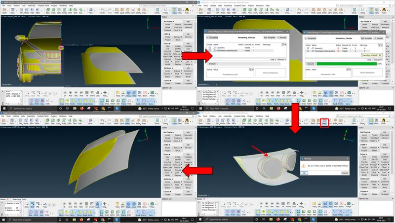
Lights:
First we isolate the lights from rest of the geometry using FOCUS tools and we will run geometry check from UTILITIES > CHECKS > CHECK MANAGER.
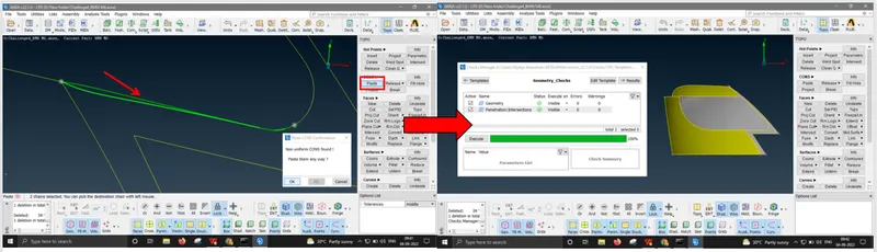
We will hide the lights front surface, the inside surfaces are not required, so we can use box select and DELETE it directly. Unhide the head light front surface, there is a pair of single CON nearby, we can paste them using CONS > PASTE.
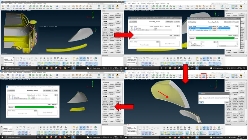
For the tail lights, we can DELETE the unwanted surfaces by isolating them.
Once the geometry cleanup is done in lights region, we can run geometry checks again to confirm there is no error.
Logo:
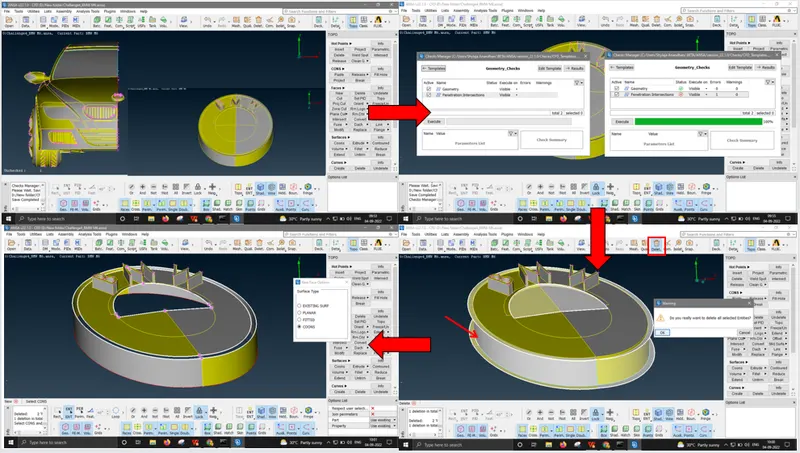
First we isolate the lights from rest of the geometry using FOCUS tools and we will run geometry check from UTILITIES > CHECKS > CHECK MANAGER.
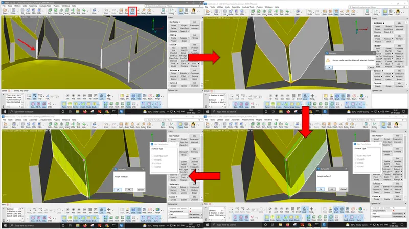
Start by deleting the unwanted surfaces present inside the logo region, using universal DELETE option. Using FACES > NEW > COONS option, we can fill the surface.
There is a very thin strip at the letters M and W, as it can create OFF elements during meshing we can delete the face and its neighbour faces to create a new face instead one by one using FACES > NEW > FITTED
Once the geometry cleanup is done in logo region, we can run geometry checks again to confirm there is no error.
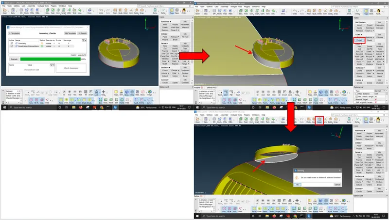
Unhide the hood beneath the logo, using CONS > PROJECT select the single con around the logo and select the hood middle click to project the con onto the hood surface. Now DELETE the face beneath the logo.
Rims and Tyres:
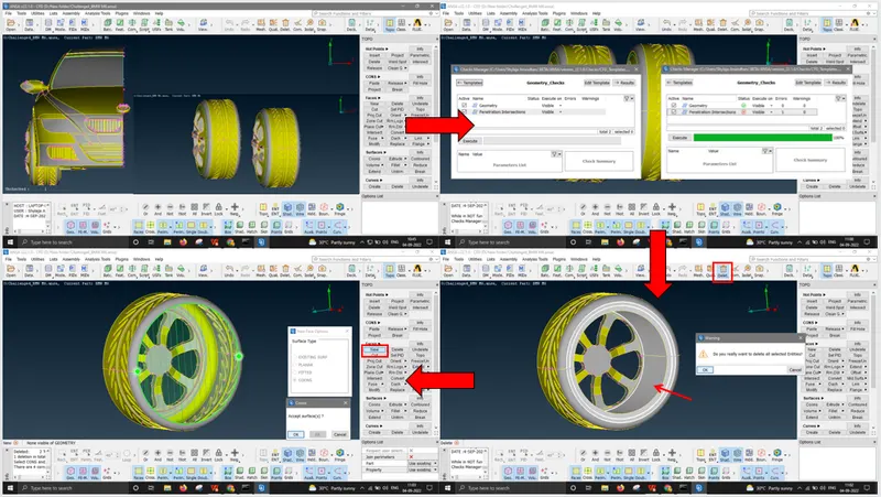
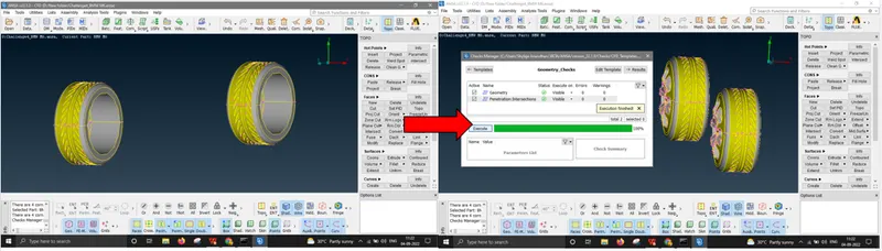
First we isolate the tyres from rest of the geometry using FOCUS tools and we will run geometry check from UTILITIES > CHECKS > CHECK MANAGER.
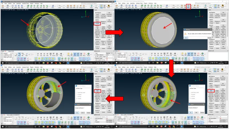
we can start to DELETE unwanted surfaces inside the tyres in order to make it into a single volume. Close the tyre face using FACES > NEW > COONS option, and CONS > PROJECT the single CON near the rim onto the newly formed surface. Using DELETE option , delete the centre circular face. Close the gap between the two single CONS using FACES > NEW > COONS option using ENT mode. Repeat the same for the other tyre as well.
Once the geometry cleanup is done in tyres region, we can run geometry checks again to confirm there is no error.
Silencer:
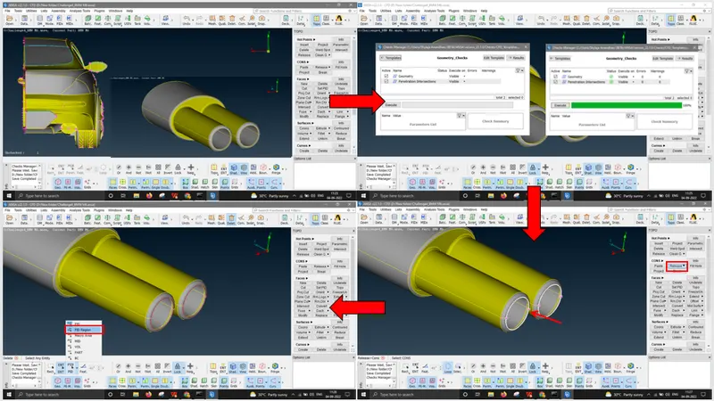
First we isolate the silencer from rest of the geometry using FOCUS tools and we will run geometry check from UTILITIES > CHECKS > CHECK MANAGER.
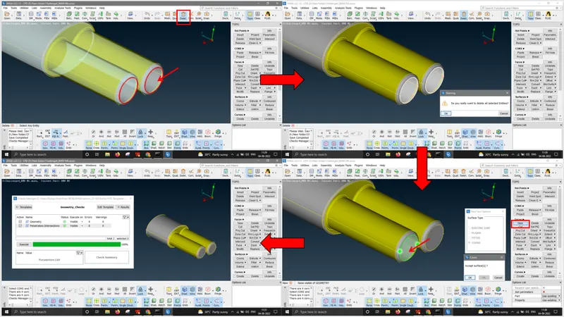
Here, the inside shell is connected to the outside shell by a single edge at the very end. So, disconnecting the single contact using CONS > RELEASE. And deleting the inside shell using universal DELETE option retains only outside shell of the silencer. Using FACES > NEW > COONS we can close the two circular gaps in the silencer.
Once the geometry cleanup is done in silencer region, we can run geometry checks again to confirm there is no error.
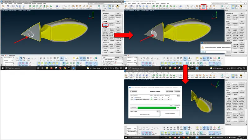
Outside rear view mirror(ORVM):
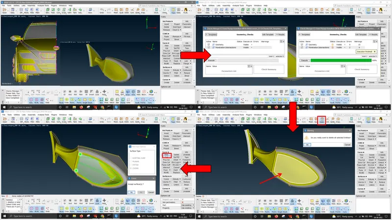
First we isolate the ORVM from rest of the geometry using FOCUS tools and we will run geometry check from UTILITIES > CHECKS > CHECK MANAGER.
There are unwanted surfaces inside the ORVM, and at the interface of ORVM and the windows, that we can DELETE directly. Close the ORVM surface using FACES > NEW > COONS.
Now, CONS > PROJECT the single CON at the ORVM interface to the windows and select the face in the windows, middle mouse click. And DELETE the centre circular face after CON projection.
Once the geometry cleanup is done in ORVM region, we can run geometry checks again to confirm there is no error.
Windows:
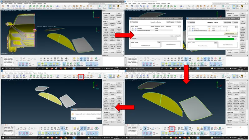
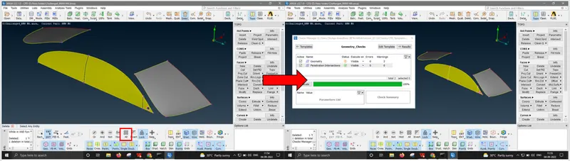
First we isolate the windows from rest of the geometry using FOCUS tools and we will run geometry check from UTILITIES > CHECKS > CHECK MANAGER.
There are unwanted surfaces inside the windows that make up individual volumes, we can hide the required outer surface of the windows using FOCUS tools and box select DELETE the inside unwanted surfaces in a single shot.
Once the geometry cleanup is done in windows region, we can run geometry checks again to confirm there is no error.
Body:
First we isolate the windows from rest of the geometry using FOCUS tools and we will run geometry check from UTILITIES > CHECKS > CHECK MANAGER.
There are many unwanted surfaces in the floor area, we can start deleting one by one. Using CONS2CURVE option at the single CON in the floor converts CONS to curves that can be used as a reference for creating faces.
At the rear wheel area, there are many contour surfaces that can be intersected using INTERSECT option. Then DELETE the faces inside the rear wheel.
There are many small surfaces, overlapping surfaces inside the flooring, we can delete one by one and close the floor using FACES > NEW > COONS.
The region around the front wheel rim has unwanted surface that can be deleted and closed for supporting water tight model, the single CONS can be resolved by creating a CUT and DELETE the small surfaces to create FACES > NEW > COONS there.
Once the geometry cleanup is done in body region, we can run geometry checks again to confirm there is no error.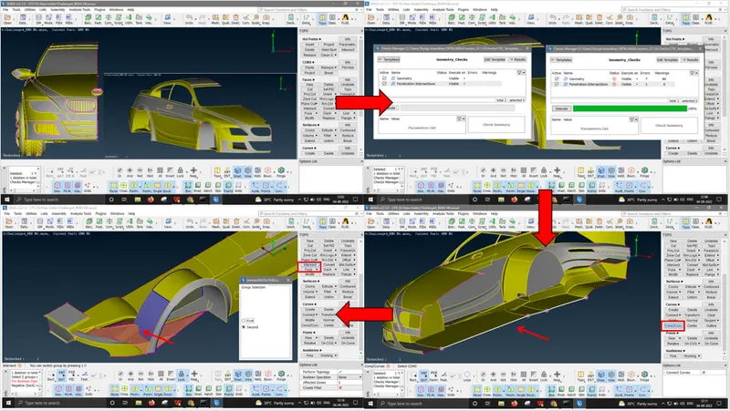
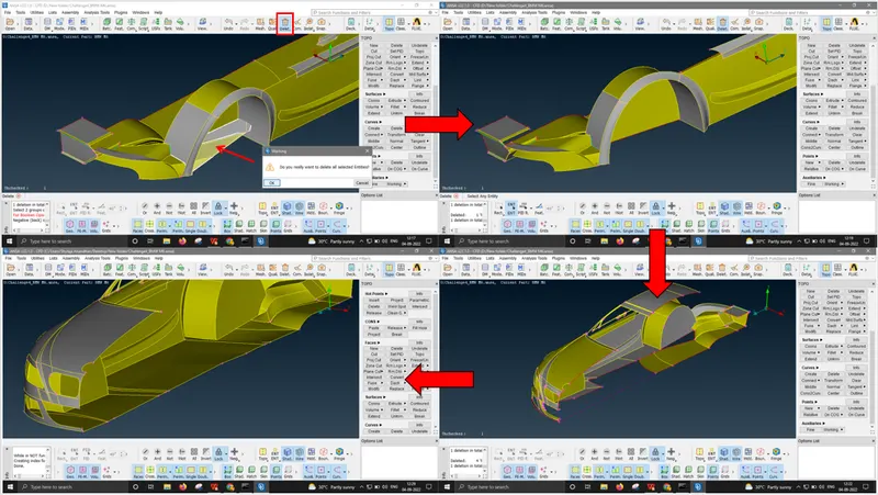
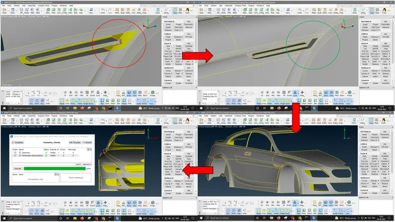
STEP 2: PID Assignment
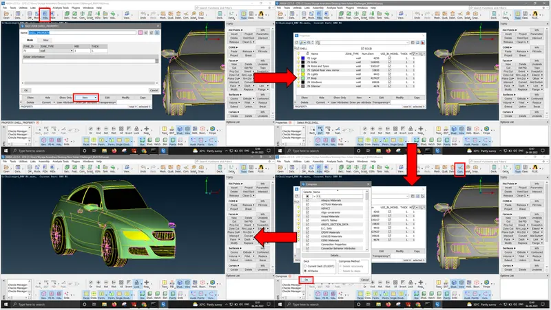
Since the geometry cleanup of all parts is done, we can proceed to assign PIDs as per the given problem statement in any order. We can create a new PID by clicking on the property button and NEW > SHELL_PROPERTY and give names as per the following.
- Body
- Lights
- Grills
- Rims and Tyres
- Optical Rear view mirror
- Window
- Silencer
- Logo
Use COMPRESS option under UTILITIES to delete the dummy PIDs permanently.
TRANSFORM:
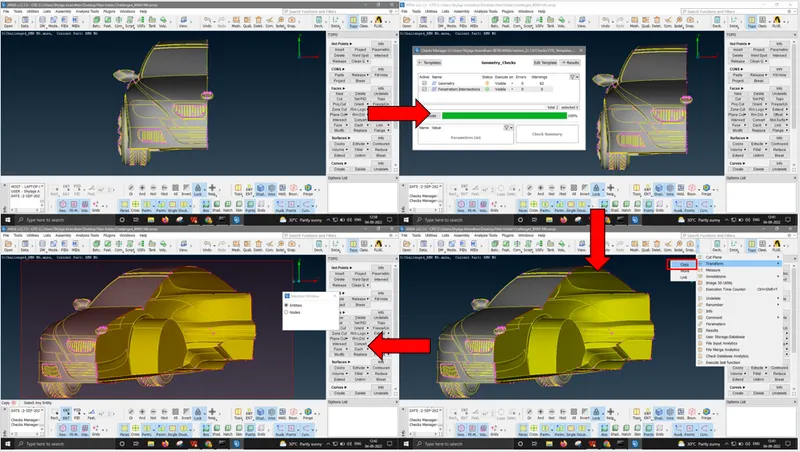
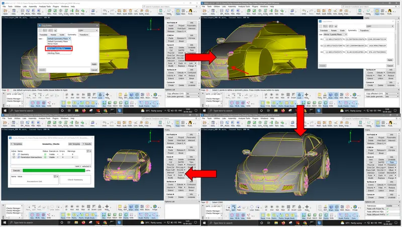
Before using this option, we can run a geometry check once to ensure there is no error in the cleaned up geometry. We have successfully completed half of the car, now we can copy paste to the other half symmetry using transform option under TOOLS > TRANSFORM > COPY a dialog box pops up select all using box select middle click, go to SYMMETRY and select MIRROR 3 POINTS PLANE , select any 3 hotpoints over the body and press middle click. Now we have our full car, we can run a geometry check to ensure no geometry errors after the transformation.
STEP 3: Surface Meshing of BMW car
Considering the length of this report, we are going to see one portion of meshing in detail with images while the same in applicable with other PIDs as well. However we shall cover the mesh parameters in detail for all PIDs.
As per the problem statement, the target mesh length for PIDs are as follows.
- Body - 3 mm
- Lights - 4 mm
- Grills - 1 mm
- Rims and Tyres - 2 mm
- Optical Rear view mirror - 2 mm
- Window - 2 mm
- Silencer - 3 mm
- Logo - 1 mm
Using the PID manager tab, we shall hide all PIDs except Grills and Logo that have 1 mm as their target length.
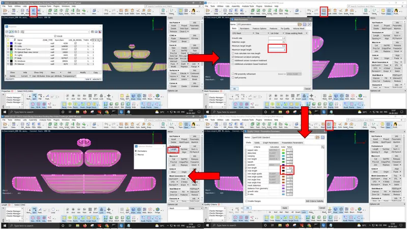
For meshing of Grills and Logo, we need to input mesh details at 4 places. For 1 mm mesh length,
Mesh parameters : min =0.2 & max =2. CFD, Tria, 1st order.
Quality criteria : min =0.2 & max =2.
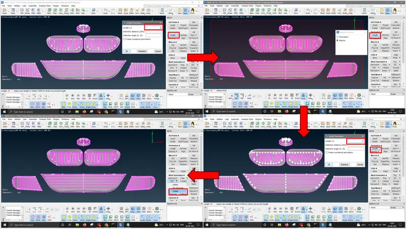
Length > perimeters : target length = 1.
Length > macros : target length = 1.
For Length > perimeters & Length > macros we need to box select the geometry before input of target length.
Now, clicking on MESH GENERATION > CFD > VISIBLE creates mesh of 1 mm length over the Grill and the Logo region. Here we have taken min as 0.2 because of the delicate letterings in the logo.
Clicking on the HIDDEN option in view controls, shows OFF elements. We can right click and IMPROVE automatically or use SPLIT option when automatic improve fails on some elements. Ensure we have zero off elements at all stages of meshing.
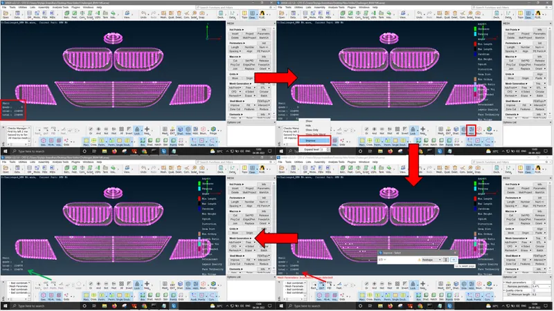
After meshing the Grill and Logo part, we shall use FREEZE option to freeze the mesh parameters and quality criteria of the grill and logo. So that while performing meshing in other PIDs, it won’t affect the grill and logo mesh.
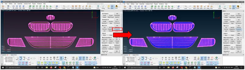
For meshing of Rims and tyres, Optical rear view mirrors and Windows, we need to input mesh details at 4 places. For 2 mm mesh length,
Mesh parameters : min =0.2 & max =3. CFD, Tria, 1st order.
Quality criteria : min =0.2 & max =3.
Length > perimeters : target length = 2.
Length > macros : target length = 2.
For Length > perimeters & Length > macros we need to box select the geometry before input of target length.
Now, clicking on MESH GENERATION > CFD > VISIBLE creates mesh of 2 mm length over the Rims and tyres, Optical rear view mirrors and Windows region. we shall use FREEZE option here as well.
For meshing of Body and Silencer, we need to input mesh details at 4 places. For 3 mm mesh length,
Mesh parameters : min =0.2 & max =4. CFD, Tria, 1st order.
Quality criteria : min =0.2 & max =4.
Length > perimeters : target length = 3.
Length > macros : target length = 3.
For Length > perimeters & Length > macros we need to box select the geometry before input of target length.
Now, clicking on MESH GENERATION > CFD > VISIBLE creates mesh of 3 mm length over the Body and Silencer region. we shall use FREEZE option here as well.
For meshing of Lights, we need to input mesh details at 4 places. For 4 mm mesh length,
Mesh parameters : min =0.2 & max =5. CFD, Tria, 1st order.
Quality criteria : min =0.2 & max =5.
Length > perimeters : target length = 4.
Length > macros : target length = 4.
For Length > perimeters & Length > macros we need to box select the geometry before input of target length.
Now, clicking on MESH GENERATION > CFD > VISIBLE creates mesh of 3 mm length over the Lights region.
Now, UNFREEZE all and zoom in to view the quality of the mesh in the interface regions, we can use MEASURE tool to check the mesh length at various PIDs. Make sure that we have zero off elements after complete meshing process.
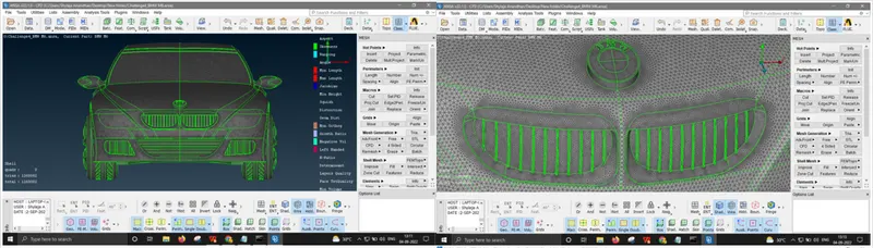
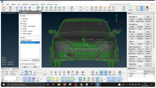
STEP 4: Computational Fluid Flow Domain creation and surface meshing of domain
CREATING THE COMPUTATIONAL FLUID FLOW DOMAIN:
The general dimensional requisite for creating a computational fluid flow domain around a geometry is described in the image below.
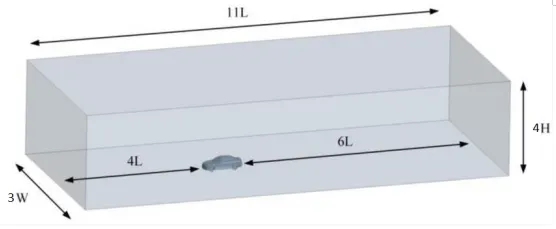
Here, L is length of the car, W is width of the car and H is height of the car.
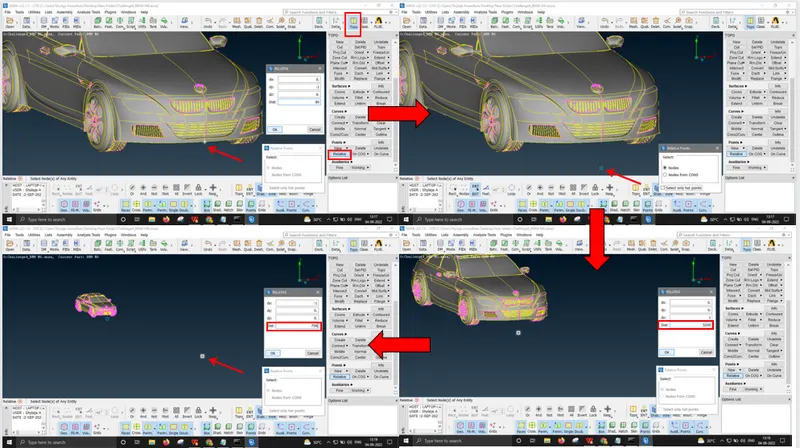
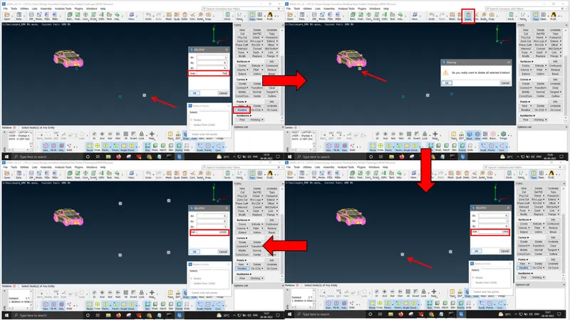
To create the computational fluid flow domain, we will create 3D points using RELATIVE method in TOPO module. From the floor of the car, we can select a hotpoint to create a 3D point relative. Our BMW car dimensions can be measured using MEASURE tool and selecting nodes across the car, for simplicity purpose we can round off the values as well.
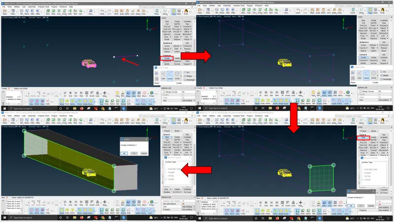
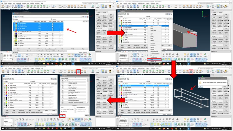
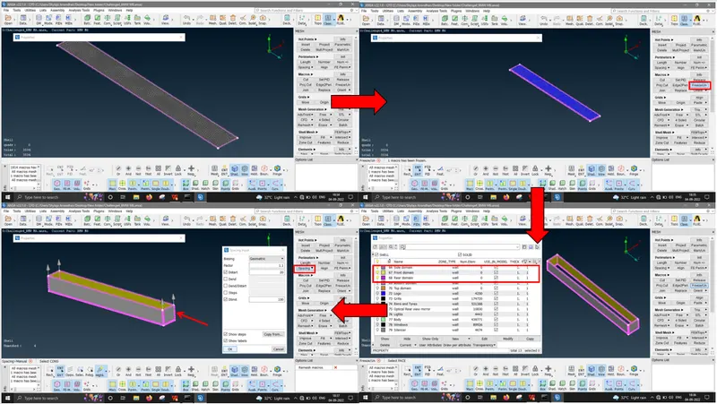
We shall consider L as 1300 mm, W as 500 mm, H as 350 mm. So the overall computational fluid flow domain size will be 14300 * 1500 * 1500. so, after creating 3D points we can use CREATE > CURVE option and connect all the 3D points so as to create the computational fluid flow domain. Then use FACES > NEW > COONS option to close all the faces. After this we will assign PIDs as top domain, bottom domain, side domain, front domain and rear domain.
SURFACE MESHING OF COMPUTATIONAL FLUID FLOW DOMAIN:
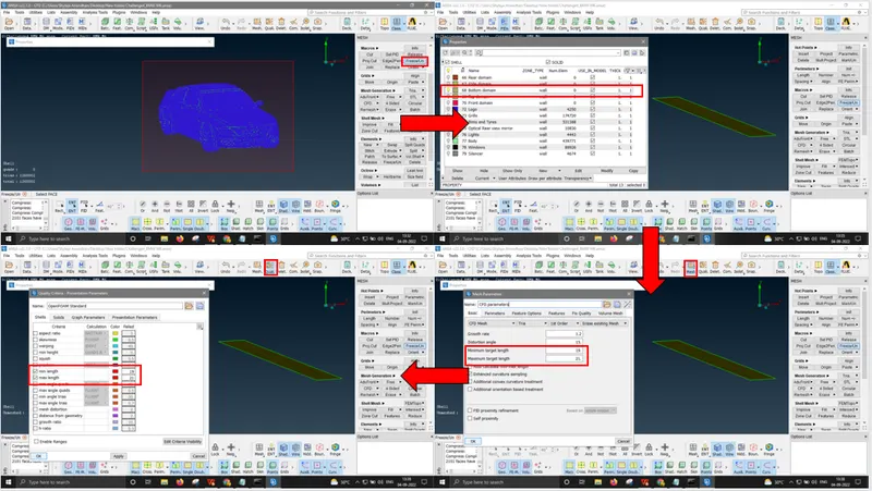
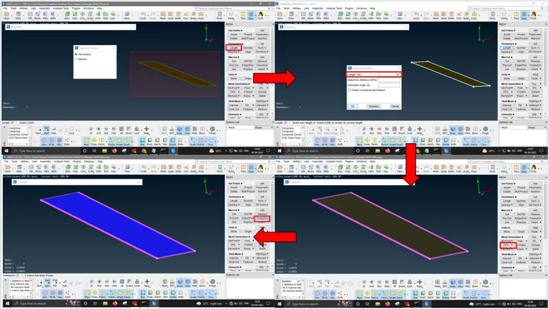
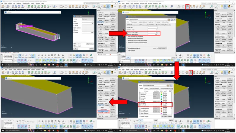
We intend to create very fine mesh near the interface of flowing fluid and the car outer surface, so we can create fine mesh along the bottom part and coarse mesh along the top part of the computational fluid flow domain. We will consider 20 mm target length in bottom part and 100 mm target length in top part.
For meshing of Bottom domain, we need to input mesh details at 4 places. For 20 mm mesh length,
Mesh parameters : min =19 & max =21. CFD, Tria, 1st order.
Quality criteria : min =19 & max =21.
Length > perimeters : target length = 20.
Length > macros : target length = 20.
For Length > perimeters & Length > macros we need to box select the geometry before input of target length.
Now, clicking on MESH GENERATION > CFD > VISIBLE creates mesh of 20 mm length over the Bottom domain. we shall use FREEZE option here.
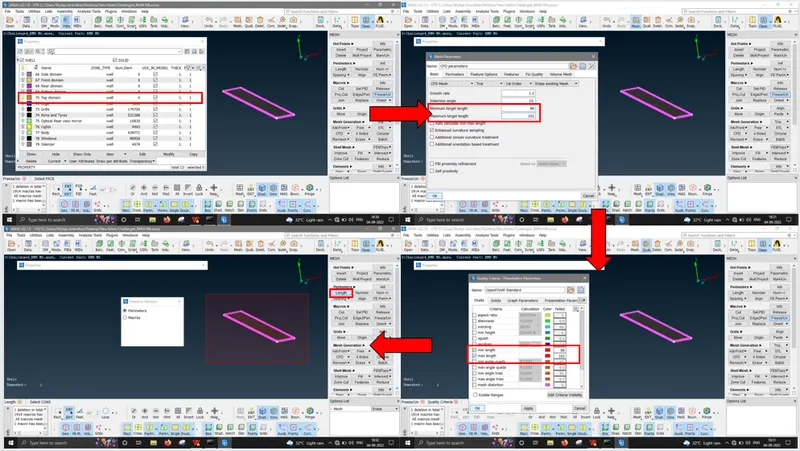
For meshing of Top domain, we need to input mesh details at 4 places. For 100 mm mesh length,
Mesh parameters : min =98 & max =102. CFD, Tria, 1st order.
Quality criteria : min =98 & max =102.
Length > perimeters : target length = 100.
Length > macros : target length = 100.
For Length > perimeters & Length > macros we need to box select the geometry before input of target length.
Now, clicking on MESH GENERATION > CFD > VISIBLE creates mesh of 100 mm length over the Top domain. we shall use FREEZE option here.
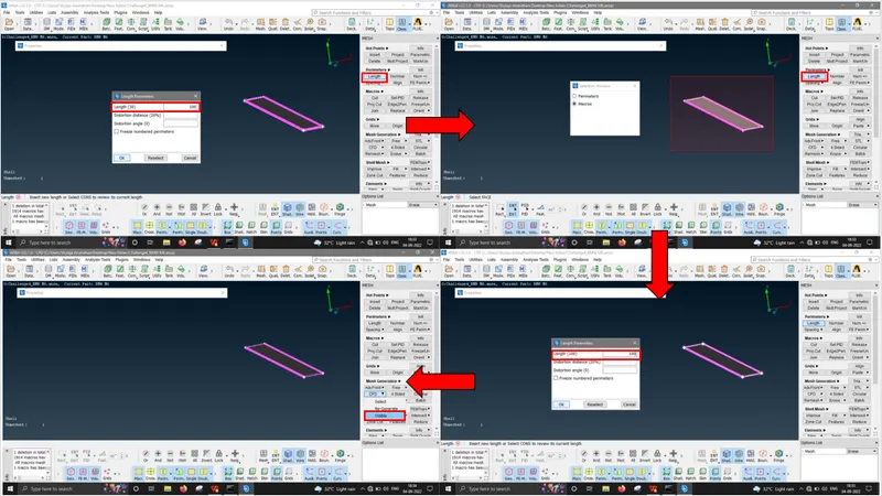
Since we want a gradual increase of mesh element from 20 mm to 100 mm from bottom to top domain, we shall use SPACING option in mesh module.
Factor shall be 1.1
Dmin shall be 20
Dlimit shall be 100
And select the four edges connecting the side domain with the front and rear domains.
For meshing of Side , front and rear domain using spacing, we need to input mesh details at 2 places. For gradual increase of mesh element from 20 mm to 100 mm length,
Mesh parameters : min =18 & max =102. CFD, Tria, 1st order.
Quality criteria : min =18 & max =102.
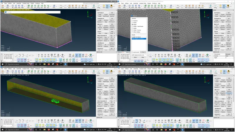
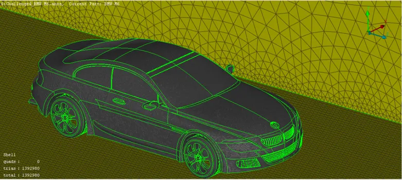
Now, clicking on MESH GENERATION > CFD > VISIBLE creates mesh that gradually increases from bottom to top, we can use MEASURE tool to verify. Now, unhiding all PIDs and use FREEZE option again with right click unfreezes all PIDs. There we have our BMW M6 in a computational fluid flow domain.
Learning outcome:
- Using Symmetry option to reduce geometry cleanup and transforming later is a good option to work with very large geometry cleanups.
- Solving convex concave CONS by splitting the surface or by deleting and creating a new one is useful.
- Cons2curve option is a life saver.
- Exploring various options to solve geometry cleanup at grill areas is interesting like we can use extend, intersect, face project, CON project. It is subjective.
- Being thoughtful and editing small surfaces in logo area prior to meshing is useful.
- Using CONS release in silencer to delete floating inside shells was interesting.
- Freezing the top and bottom domains in computational fluid flow domain while meshing saves time and computational stress as well.
Result:
Thus the geometry cleanup, surface meshing and creation & meshing of computational fluid flow domain is successfully completed as per the respective target mesh lengths given.
Conclusion:
The overall process of geometry cleanup and surface meshing of the BMW M6 car was quite challenging and interesting, some new tools were used, some alternate approach to geometry cleanup were explored as well. The meshing part was challenging for the computational fluid flow domain, but using some smart approach of meshing in parts and using freeze also reduced the computational time from hours to minutes. Hence, the week 4 challenge is successfully completed & ANSA file is shared via gdrive link.
https://drive.google.com/file/d/1b2ifKMXdt0adp2J5Ut_JA2K8D-6bYomq/view?usp=sharing