Week 3 Challenge : CFD meshing on Turbocharger
Week 3 Challenge : CFD meshing on Turbocharger
Aim/Objective:
For the given CAD model of Turbocharger, check for the geometrical errors, Create and assign PIDs, Perform surface mesh with the following target lengths as per PIDs.
- Blade stage-1 = 1 mm
- Blade stage-2 = 1 mm
- Impeller = 2 mm
- Shaft rotor = 1 mm
- Turbo casing = 5 mm
- Compressor casing = 5 mm
- Inlet casing cover = 5 mm
And perform volumetric mesh for the required volumes.
Procedure:
We will be following 4 major steps
STEP 1: Geometry cleanup
STEP 2: PID assignment
STEP 3: Surface Meshing
STEP 4: Volumetric meshing
Each step has a series of sub-steps to be followed, we shall be discussing in detail along with snapshots of the sequences wherever required.
The first step is to open the ANSA in performance 3 mode with CFD enabled. Open the given CAD model of the Turbocharger from FILE > OPEN. Default view of the geometry is wireframe, we shall turn on SHADOW mode for better visibility.
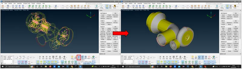
Let us start the geometry cleanup.
STEP 1: Geometry cleanup
GEOMETRY CHECK: Let us start with a geometry check, under the TOOLS > CHECKS MANAGER > GEOMETRY select the geometry to run a geometry check along with the penetration check too. Click on the EXECUTE , it shows all the geometric and penetration errors.
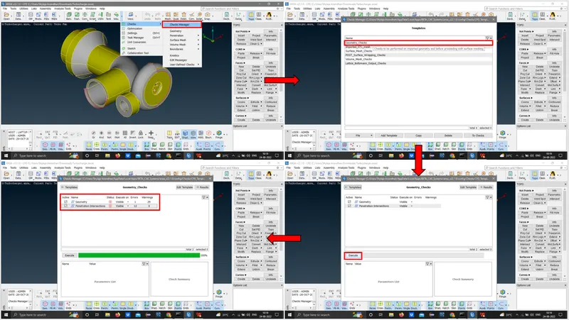
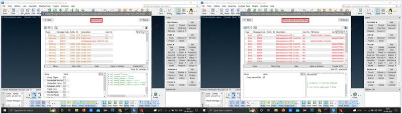
We can now start our geometry cleanup like fixing of single CONS, triple CONS, missing faces, closing openings, intersection and penetration errors.
*NOTE: Do not get confused with the geometry option available outside the CHECK MANAGER drop down, it does not include penetration errors. Since we are performing volumetric mesh, we need to cleanup the penetration errors too.*
FIXING GEOMETRY ERRORS: Geometry errors include single CONS, triple CONS, cracks, missing surfaces, overlapping surfaces etc,…in this case we can see that an additional PID is overlapping on the outer casing (since we haven’t assigned PID names as per the problem statement, let us now stick with outer casing instead of Turbo casing), we can simply delete that overlapping PID from PROPERTY dialog box under LISTS tool bar.
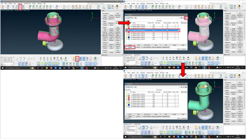
*We are going to fix all geometric errors eventually, in this report we shall cover the important ones that are hard to fix, or the ones on which we have used new functions.*
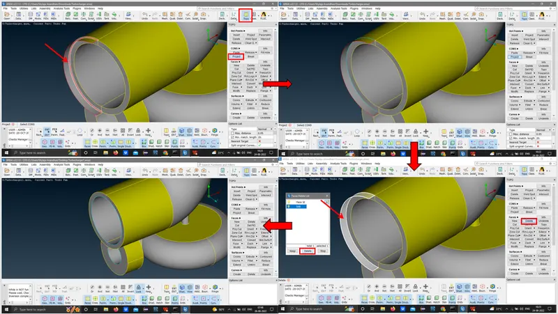
There is an extra projected surface at the mouth of one end of outer casing, we cannot delete that in one go, so we shall first PROJECT the CONS of the outer circular face onto the outer surface of the outer casing using TOPO > CONS > PROJECT. Using FACES > DELETE or by using UNIVERSAL DELETE we can now delete the additional unnecessary projection alone by left click and middle mouse button.
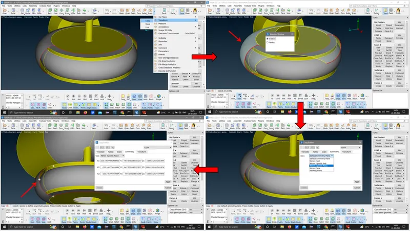
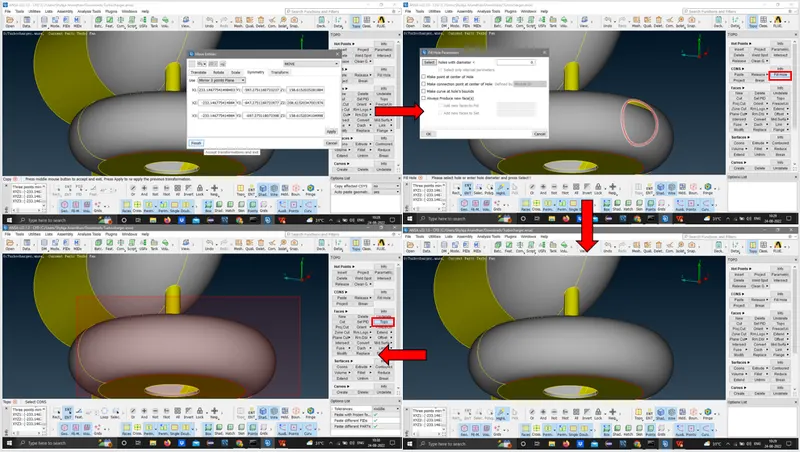
We have a missing surface on the Compressor casing, solving this is subjective but the easy way is to simply copy the existing surface by using TRANSFORM tool. To use this tool we need 3 HOTPOINTS on the cross section side single CONS, so we shall insert a new hotpoint using HOTPOINT > INSERT. Now, under UTILITIES > TRANSFORM > COPY select the existing half portion of the compressor casing with ENTITIES selected in the popup dialog box and click middle mouse button. Another dialog box appears now, select SYMMETRY > MIRROR 3 POINT PLANE in the drop down. Now select the 3 hotpoints on the single CONS we inserted earlier click middle mouse button, popup appears select OK, click FINISH.
We have copied the surface onto the missing surface area. We have a hole here, we can simply use FILLHOLE option and close it. It can be noticed we have single CONS here, we can perform TOPO operation to fix it.
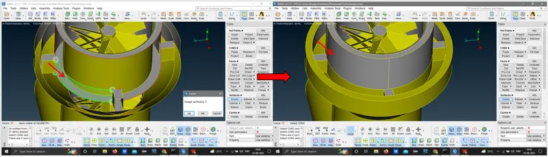
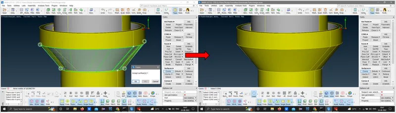
There is a missing surface at the outer casing near to the blade 1 region, we can use NOT function in focus tool section to have a better view of it. We shall use FACES > NEW > COONS or SURFACES > COONS to fix it (to use the function just left click on the function and select the single CONS using left mouse button and check the preview, if not satisfied click the ALT, finally press middle mouse button) but this fix requires 2 steps. First we fix the surface on the 2 supports and the use LOOP to select the remaining single CONS to fix it.
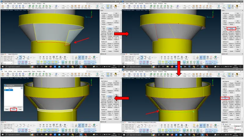
FIXING PENETRATION ERRORS: On the interface of the conical section to cylindrical section on the outer casing, we have an intersection error. We cannot create an intersection there, since the intersection is not uniform. So, we can either delete both surfaces or delete conical one and edit the cylindrical one to match the neighbouring surfaces (again, this is subjective - fix varies on each ones perspective) and create a new conical surface.
We will edit the delete the conical surface using FACES > DELETE. Edit the cylindrical surface by using HOTPOINT > PROJECT make a cut at the extra projected area, and delete the unnecessary portion using FACES > DELETE. Now, create a new conical face using FACES > NEW > COONS with LOOP option enabled.
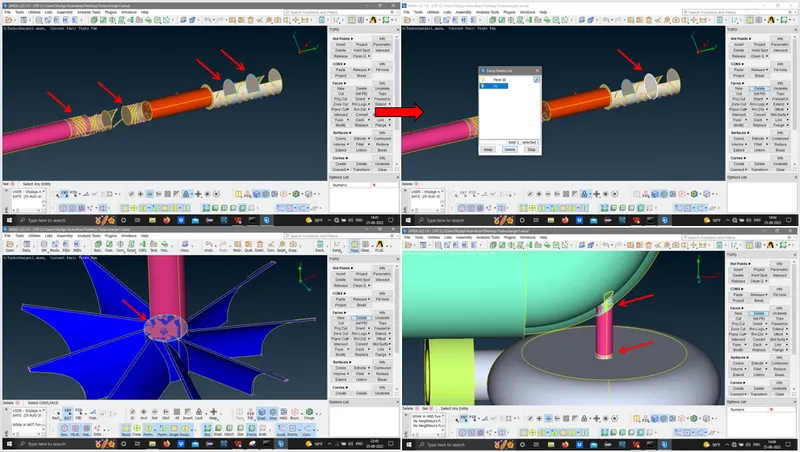
Deletion of overlapping surfaces in the rotor shaft & outer casing interface and compressor casing & rotor shaft interface. Inside the blades and shafts, at the interface of impeller and rotor shaft are to be deleted. We will be using FOCUS commands extensively here, CONS > PROJECT, FACES > DELETE, TOPO operations are used.
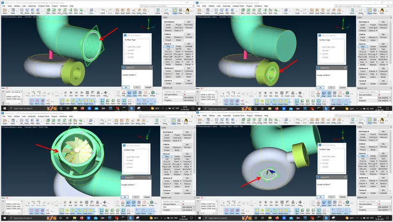
Closing of the open surfaces, there are open faces at outer casing inlet and outlet, compressor casing inlet and outlet which are to be closed by FACES > NEW > FITTED option. (We can use either of the options such as planar, fitted, coons by trial and error with the geometry checks)
Once the geometry cleanup is done, we will run geometry check once again to ensure all the errors are resolved. Some triple CONS are needed, excluding them all other errors are to be resolved. (NOTE: The baffle region inside the interface of compressor casing and inlet casing cover is isolated from the geometry, we can either delete it completely or resolve it to proceed further).
STEP 2: PID assignment
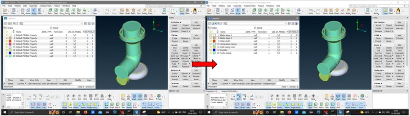
PIDs are already available In this geometry, we just have to check with the viewport model and rename it accordingly. As per the given problem statement, we will name them as following,
1.Blade stage-1
2.Blade stage-2
3.Impeller
4.Shaft rotor
5.Turbo casing
6.Compressor casing
7.Inlet casing cover
After the assignment of PIDs, the DEFAULT SHELL PROPERTY is invalid now, we can delete it using COMPRESS option in UTILITIES tool bar.
STEP 3: Surface Meshing
As per the problem statement, we have to mesh the respective PIDs with varying mesh element sizes as follows,
1.Blade stage-1 = 1 mm
2.Blade stage-2 = 1 mm
3.Impeller = 2 mm
4.Shaft rotor = 1 mm
5.Turbo casing = 5 mm
6.Compressor casing = 5 mm
7.Inlet casing cover = 5 mm
We will start meshing in MESH module from smaller mesh element size PIDs first, using NOT function or from PROPERTY DIALOG BOX we shall hide outer casing, compressor casing, inlet casing cover, and impeller. We will be left with Blade stage 1 & 2 along with shaft rotor, all three have common mesh element size of 1 mm.
For meshing, we need to input mesh details at 4 places. For 1 mm mesh length,
Mesh parameters : min =0.5 & max =2. CFD, Tria, 1st order.
Quality criteria : min =0.5 & max =2.
Length > perimeters : target length = 1.
Length > macros : target length = 1.
For Length > perimeters & Length > macros we need to box select the geometry before input of target length.
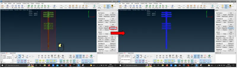
Now, clicking on MESH GENERATION > CFD > VISIBLE creates mesh of 1 mm length over the Blade stage 1 & 2 and shaft rotor region. Since the impeller is connected to the same geometry but we need different mesh length of 2mm over it, we can now use FREEZE option left box select the newly generated mesh to freeze its mesh settings. This function enables us to use varying mesh length within the same geometry without affecting its neighbouring surfaces.
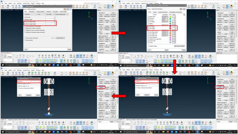
For meshing of impeller, we shall use the following. For 2 mm mesh length,
Mesh parameters : min =0.5 & max =3. CFD, Tria, 1st order.
Quality criteria : min =0.5 & max =3.
Length > perimeters : target length = 2.
Length > macros : target length = 2.
Now, clicking on MESH GENERATION > CFD > VISIBLE creates mesh of 2 mm length, now we need to unfreeze using FREEZE and right box select. Again freeze with blade stage 1 & 2, shaft rotor, and impeller also. So, when we mesh the outer parts, these inner parts stay unaffected.
For meshing of Turbo casing, inlet casing cover and compressor casing, we shall use the following. For 5 mm mesh length,
Mesh parameters : min =0.5 & max =7. CFD, Tria, 1st order.
Quality criteria : min =0.5 & max =7.
Length > perimeters : target length = 5.
Length > macros : target length = 5.
Now, clicking on MESH GENERATION > CFD > VISIBLE creates mesh of 5 mm length.
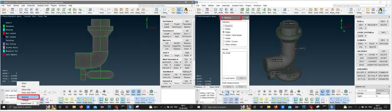
We can always verify mesh element size from MEASURE option in utilities.
Clicking on the HIDDEN option in view controls, shows OFF elements. We can right click and IMPROVE automatically or use SPLIT option when automatic improve fails on some elements.
STEP 4: Volumetric Meshing
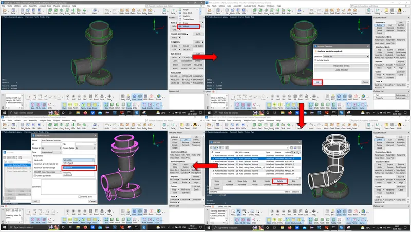
After surface meshing, expanding the right arrow near the module selection region drops down an option called VMESH clicking on that shows volumetric mesh module. In this case, we shall be generating TetraCFD type mesh elements.
First step in volumetric meshing is to define the volumes, clicking on VOLUME > DEFINE automatically defines the existing volumes. Since our focus is in CFD, we can delete the solid volumes (the volume between outer and inner shells) and focus on fluid volumes (the volume within inner shell where fluid flows). In this case we have 3 fluid volumes, one inside turbo casing, one in compressor casing, one in inlet casing cover.
Now, double clicking on the fluid volume pops up a dialog box, in which we will select the mesh type as TetraCFD. Similarly, we shall do for other two as well.
(Opening the property dialog box, we can see the newly generated volumes as FLUID type while other PIDs as WALL type).
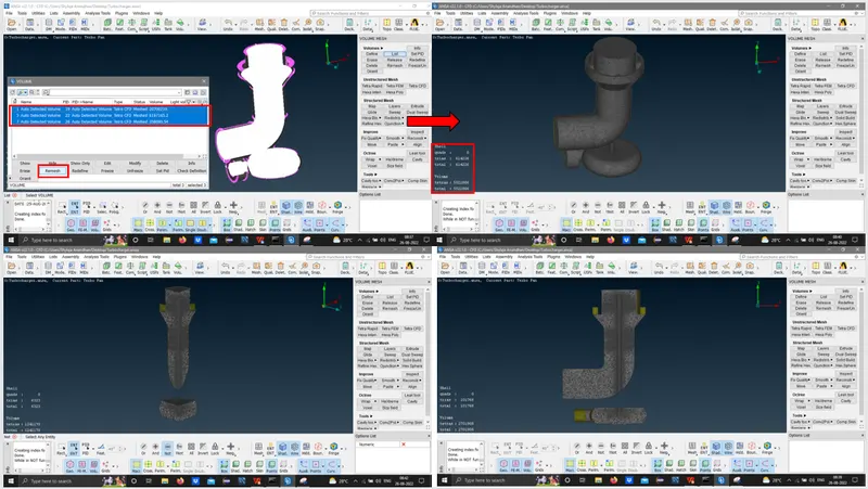
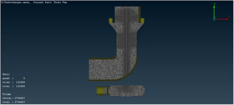
Now, Selecting all 3 volumes and clicking on REMESH generates volumetric mesh on the fluid volumes. We can use a CUTPLANE under UTILITIES and select desired plane for viewing the volumetric mesh or simply use NOT function in ENTITIES mode and box select half of the geometry to view the volumetric mesh.
Learning outcome:
- Use of FREEZE function drastically reduces confusion while surface meshing.
- Use of PROJECT function at impeller region and shaft overlap region eases the unwanted face deletion.
- TRANSFORM function usage to reduce time in geometry cleanup
- PID wise deletion to save time in geometry cleanup
- Defining fluid volumes and differentiating them from solid volumes.
- How smaller surface mesh length affects the volumetric mesh near to the surfaces is understood. The nodes in surface mesh becomes the connecting points for volumetric meshes is observed by cross section of the volumetric mesh.
- Using HIDDEN to show OFF elements and improving using SPLIT in worst cases.
Result:
Thus the geometry cleanup, surface meshing and volumetric meshing of the given turbocharger model is performed as per the given respective target mesh lengths.
Conclusion:
The overall process of volumetric meshing and its relation to surface meshing is observed by the cross section where we come to know that the surface mesh nodes are the connecting points to the volumetric mesh. Hence, the week 3 challenge is successfully completed & ANSA file is shared via gdrive link.
https://drive.google.com/file/d/1VU-T11vHcC7WB0g17YZxdZ1RdqcGSEqR/view?usp=sharing