Week 2 Challenge : Surface meshing on a Pressure valve
Week 2 Challenge : Surface meshing on a Pressure valve
Aim/Objective:
To perform geometry cleanup and surface meshing of given pressure valve CAD model with tria type mesh of length 1 mm, 3 mm & 5 mm respectively.
Procedure:
Let us open the given CAD model of the pressure valve in ANSA with performance 3 mode and CFD mode on.
The default file opening view is in wireframe, so switch on SHADOW mode.
STEP 1: Geometry cleanup
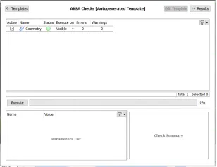
To get a better idea about the geometry flaws,let us first run a quick geometry check under CHECK MANAGER > GEOMETRY. Make sure to select single CONS as well, click EXECUTE.
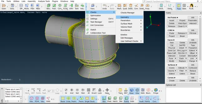
Once the geometry check is done, it should look like this.
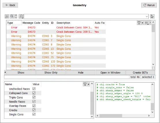
Now,we can either select the warning in the geometry check pop updialog box with PICK option enabled, the selected warning will be highlighted in the viewport.
Or, we can simply disable the double CONS, triple CONS in the view menu with only single CONS enabled and also disable SHADOW. This shows only the single CONS in the viewport. It should look something like this,.
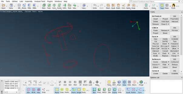
So, we now know what are the single CONS to be fixed.
FIXING single CONS: The single CONS that we know from the geometry check need to be fixed, here fixing means we need to close all the open surfaces either by deletion and adding a new face or by introducing a new face in open ends (eg, inlet/outlet openings).
Inorder to close an open surface, we can use
(method 1) FACE > NEW > COONS select the open surface by either selecting individual single CONS in ENTITY mode or by enabling LOOP option and simply selecting any single CONS of the open surface.
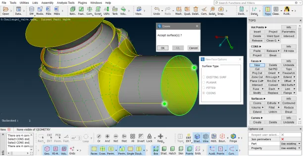
(method 2) FILL HOLE option, click and select on the open surfaces (for many small cracks nearby we can even use box select) now clicking middle mouse button the open surfaces will be closed.
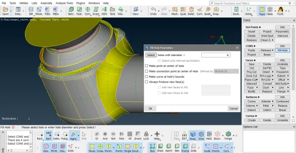
NOTE: We can use any method as per the outcome and the relevance to the outcome in the preview of the function. Difference is, in FILLHOLE command there is double CONS present in the closed surfaces whereas in FACE > NEW option we will have double CONS present in the newly formed surfaces.
USE OF FOCUS TOOLS: While we are fixing the single CONS, we will be using focus tools like or, and, not, all, invert tools. The following comparison shows use of not tool for hiding out an outer surface so as to view the inner single CONS to fix it.
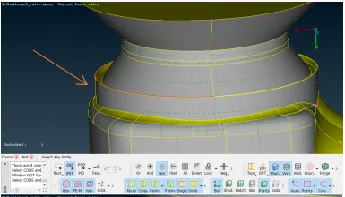
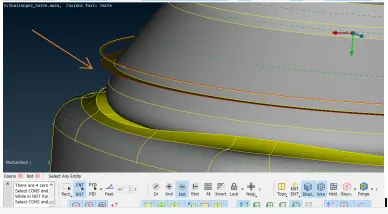
In a similar manner, we will be closing all the single CONS identified from geometry check and introduce new surfaces in the inlet, outlet and the bottom cap regions too.
To verify all the single CONS are fixed we can simply press ctrl and shift to view in wireframe mode or rerun the geometry check again.
Geometry cleaned wireframe model should look like this,(Triple CONS is turned OFF here, since the bottom cap triple CONS is required. This triple CONS should not be considered as a geometric flaw)
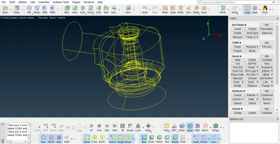
The geometry check results after the geometry cleanup will look like this (triple CONS disabled)
STEP 2: Assigning PID’s to the geometry
Now that the geometry cleanup is done, we can start assigning PID’s.
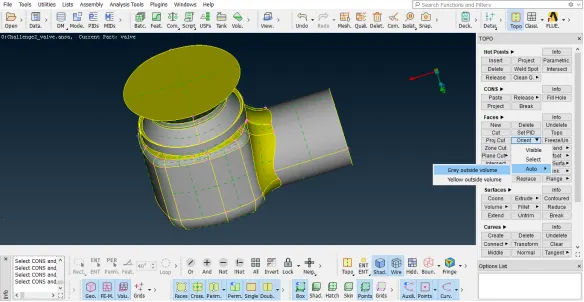
Optional step ( since the geometry looks yellow and grey surfaces mixed together in both outside the geometry and inside the geometry, we can fix it using ORIENT > AUTO > GREY OUTSIDE VOLUME option in TOPO.)
Note: GREY colour represents POSITIVE face, YELLOW colour represents NEGATIVE face.
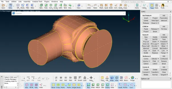
Unassigned PID SHELL geometry should look like this, with changing from ENTITY to PID option in view control box.
And clicking on the PIDs option in the tool bar, it shows only one default SHELL property.
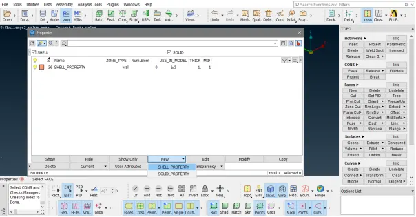
To assign new PIDs, simply right click on the property dialog box, or use the NEW option available in the dialog box. NEW > SHELL PROPERTY, a new dialog box pops up asking for a name, and other details. Input the name and click OK and save it. We can use distinguishing colours for each PIDs for better visibility as well. Good practice is, creating the required no: of PIDs before assigning and assigning one by one. Once this step is done, it should look like this.
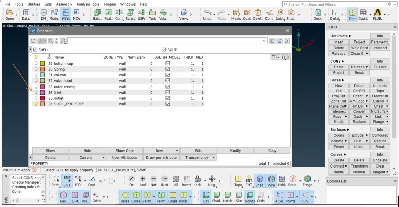
Note: Here, unassigned PIDs will have a WHITE bulb, visible PIDs will have YELLOW bulb, assigned PIDs will have GREY bulb. We can click on the bulb to turn ON/OFF the visibility of the respective PIDs, box select and use the same for the selected set of PIDs also.
During PID assignment, there is a wide scope of usage of the focus tools like NOT,OR,INVERT,ALL tools.
After PID assignment, all the bulbs in the property ID should either be grey if hidden or should be yellow. Also, the default shell property that was originally present is non existent now we can delete that using the COMPRESS function.
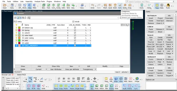
Once the PID assignment is done, it should look like this.
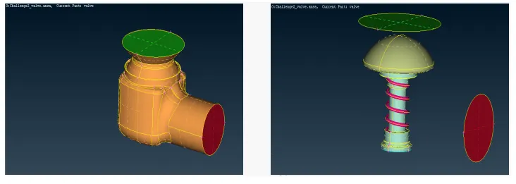
STEP 3: SURFACE MESHING OF THE PRESSURE VALVE
After assigning PIDs, we can proceed with meshing operation. Since we are having 3 cases of mesh lengths in the challenge statement, we shall discuss in detail for first case I.e,. mesh length of 1mm. Other two cases follow the same steps but with minor change in the input mesh length alone of 3mm and 5mm in respective cases.
Before meshing, under MESH Module we can start joining very sharp faces, very small surfaces into the neighbouring surfaces so as to improve the mesh quality. For joining, under MESH module In MACROS select CUT and right click on the CONS to be removed.
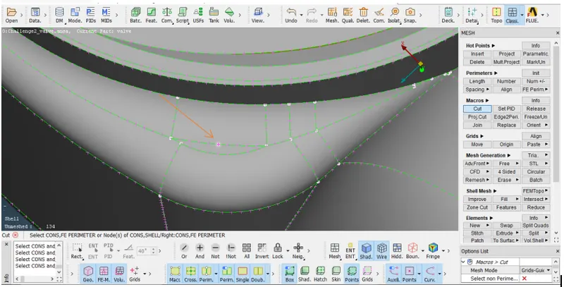
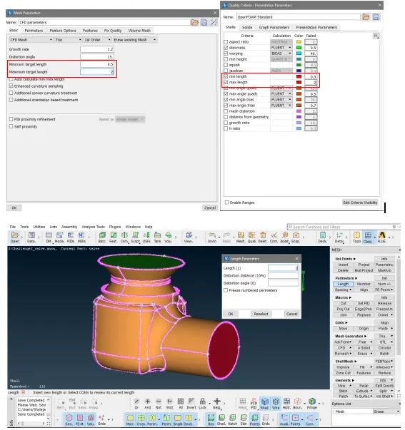
Once that is done, we can start to input mesh length in Quality criteria, Mesh parameters(use CFD mesh with tria type, 1st order), and in Perimeter and Macros of LENGTH command. In our first case it is 1mm target length, so we will be using 0.5mm as min length and 2mm as max length in mesh parameters and quality criteria and target length 1mm in length > perimeter and length > macros.
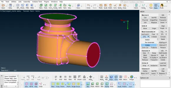
After preparing for meshing, we can mesh the geometry now using Mesh Generation > CFD > Visible function.
After meshing, the geometry looks like this on the inside and outside.
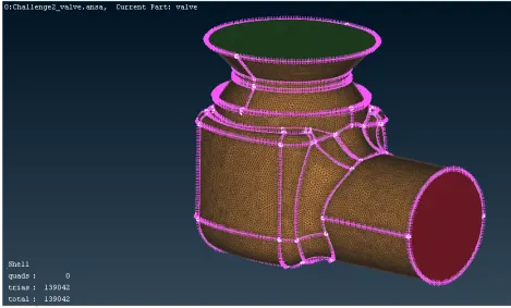
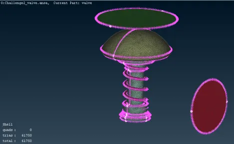
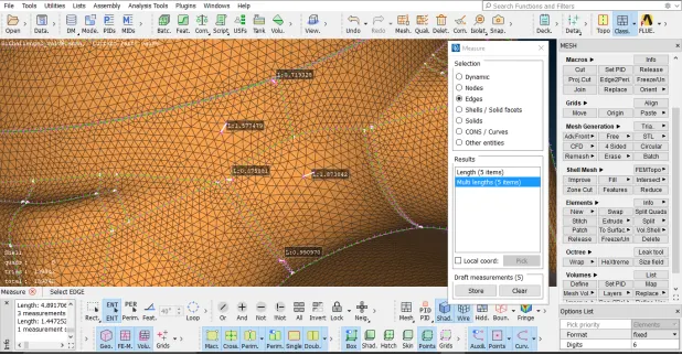
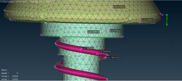
We can use MEASURE tool to check the mesh length in all the PIDs also. Measurement of mesh in all PIDs is provided with the ANSA file attached for all 3 cases. In all 3 cases spring mesh length is maintained as 1mm, since its diameter is very small when compared to the 3mm and 5mm target lengths.
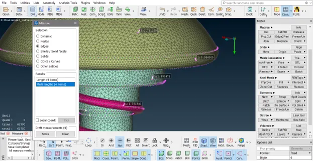
Fully meshed and measured mesh geometry looks like this, a closer view is also provided to understand the meshing algorithm and the use of join operation performed earlier.
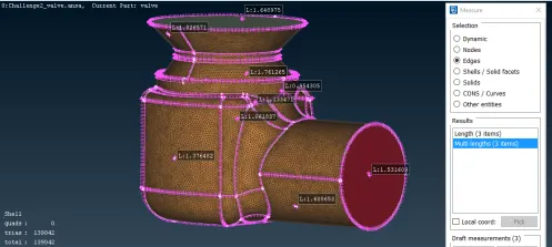
For case 2, I.e,. Mesh target length 3mm. We can change the min max lengths in mesh parameters and quality criteria to 0.5 min and 4 max. In length parameters and macros, input target length as 3mm. Erase the existing 1mm mesh and perform CFD mesh again with the new inputs in place.
We should be getting something like this.
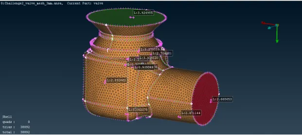
For case 3, I.e,. Mesh target length 5mm. We can change the min max lengths in mesh parameters and quality criteria to 0.5 min and 7 max. In length parameters and macros, input target length as 5mm. Erase the existing 1mm mesh and perform CFD mesh again with the new inputs in place.
We should be getting something like this.
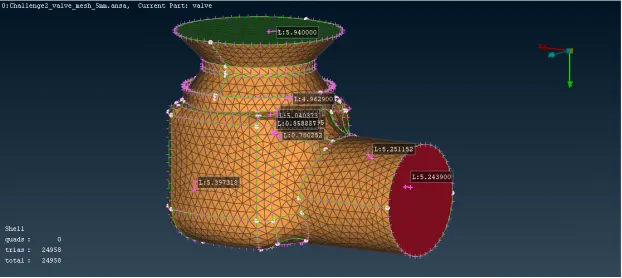
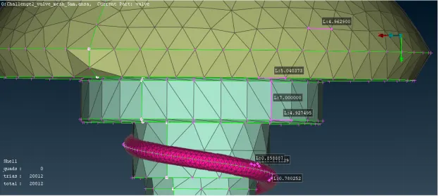
We have successfully meshed the given pressure valve model for all 3 cases of mesh length 1mm, 3mm and 5mm.
LEARNING OUTCOMES:
- The target mesh length depends on the dimensions of the geometry on which the mesh is to be applied.
- Joining of CONS is very important to get a uniform and clean mesh.
- As we reduce the mesh target length finer mesh is obtained (obviously), all the contours in the surfaces are captured accurately.
- As the target length reduces, more computational time, more no of trias, more the size of the ANSA file as well.
RESULT:
The Surface meshing of the given pressure valve CAD model is completed for all 3 cases. It is observed that lesser the mesh target length, finer the mesh, longer the computational time(incase of very large geometry like an airplane), more number of discrete elements(trias) in lesser target length. Also, the part dimensions decide what target length to be used (spring dimensions reference in this case). Overall result produces very good mesh for 1mm target length (case 1), average results for 3mm target length (case 2), and ok result for 5mm target length (case 3).
CONCLUSION:
Hence, the challenge is successfully completed and all 3 ANSA files are shared with gdrive link.
https://drive.google.com/file/d/1D2hxQJPcwPV2TCLeD1Ixc3-VocKgTJtl/view?usp=sharing