Project 1 : CFD Meshing for Tesla Cyber Truck
Project 1 : CFD Meshing for Tesla Cyber Truck
Aim/Objective:
For the given CAD model of Tesla Cyber Truck we shall check and solve all geometrical errors and Assign appropriate PIDs, Perform meshing with the appropriate Target length and element Quality criteria. And create a computational fluid flow domain, surface mesh the flow domain as well.
Procedure:
We will be following 4 major steps
STEP 1: Geometry cleanup
STEP 2: PID assignment
STEP 3: Surface Meshing of Tesla Cyber Truck
STEP 4: Computational Fluid Flow Domain creation and meshing
Each step has a series of sub-steps to be followed, we shall be discussing in detail along with snapshots of the sequences wherever required.
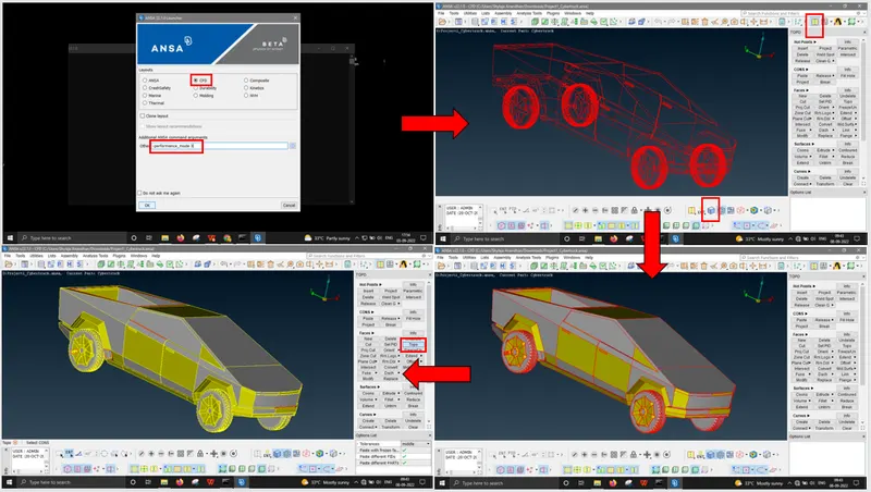
The first step is to open the ANSA in performance 3 mode with CFD enabled. Open the given CAD model of the Tesla Cyber Truck from FILE > OPEN. Default view of the geometry is wireframe, we shall turn on SHADOW mode for better visibility.Let us start the geometry cleanup. Since the model is fully in single CONS view while opening, we can use TOPO once to clear it.
STEP 1: Geometry cleanup
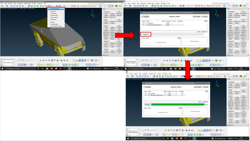
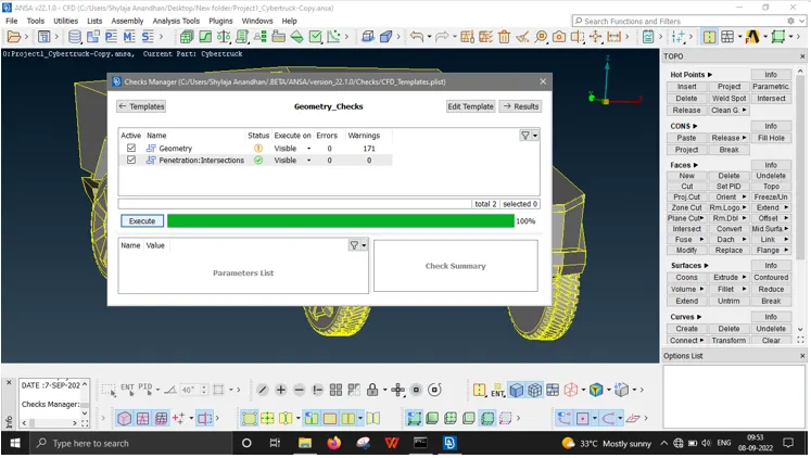
GEOMETRY CHECK: Let us start with a geometry check, under the TOOLS > CHECKS MANAGER > GEOMETRY select the geometry to run a geometry check along with the penetration check too. Click on the EXECUTE , it shows all the geometric and penetration errors.
In order to create a water tight model, we need to delete unnecessary volumes inside the fluid flowing region and close all openings. Since our area of interest is the volume outside of the Tesla Cyber Truck model, we can simply delete unnecessary volume inside the car model and make the car body as a single water tight model.
Resolving single CONS:
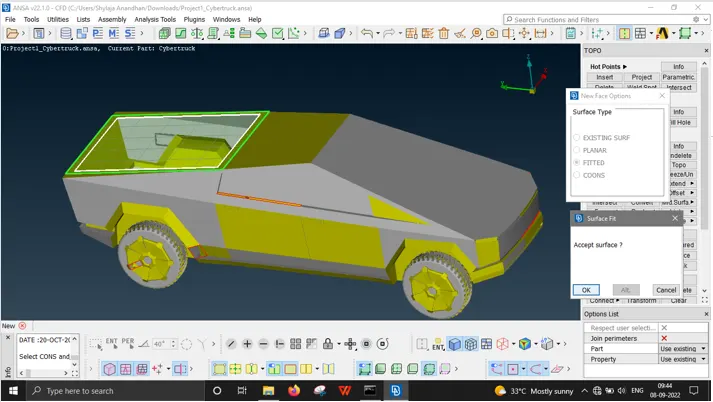
There a single CONS, and open surfaces in the Tesla Cyber Truck model. We can either view it from the geometry check or we can turn off double CONS and triple CONS in the view options with only single CON enabled it is easy for us to view all the single CONS in the viewport.
Resolving the single CONS in this case is very easy, all are missing surfaces. So using FACES > NEW > FITTED option and selecting the single CONS one by one and closing the surfaces should do.
Resolving penetration error:
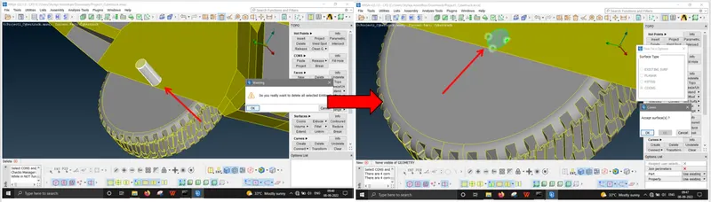
There are a few penetration error, that is unwanted surface cross overs. We can get rid of them by intersecting those surfaces using INTERSECT option and deleting using universal DELETE option. Or by simply identifying whether the surface is necessary or not and deleting it from the geometry. In this case, we can delete the cylindrical projections fro the tyres into the body and create tyres as a separate volume from the body.
In this case, we have intersection error at the front bumper areas, and at the front mid portion. We can use the above discussed methodology to resolve them.
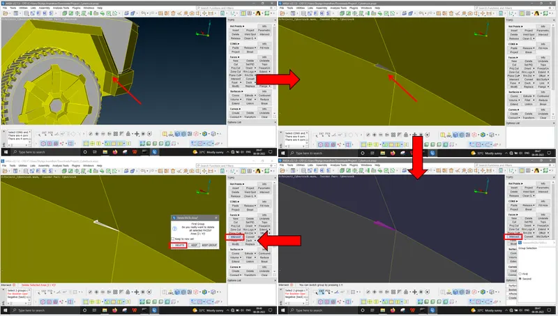
Once we are done with geometry cleanup, run a geometry check to confirm it. In this case, we can ignore the warnings in geometry checks regarding the convex, concave and mixed CONS. Ensure we have zero penetration errors. So, we are good to go to PID assignment.
STEP 2: PID Assignment
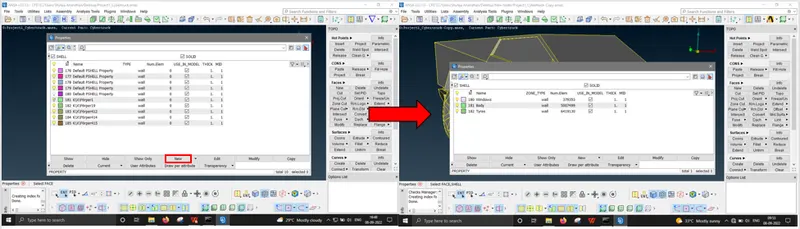
Since the geometry cleanup of all parts is done, we can proceed to assign PIDs. We can create a new PID by clicking on the property button and NEW > SHELL_PROPERTY and give names as per the following.
- Body
- Tyres
- Window
Right click on created PID and click assign and select the faces for PID assignment. We can use box select wherever required. Once we are done with PID assignment, there will be dummy PIDs left, we can use COMPRESS option under UTILITIES to delete the dummy PIDs permanently.
STEP 3: Surface Meshing of Tesla Cyber Truck
For the Tesla Cyber Truck model we shall consider the following target length for surface meshing. The target length can be decided based on the smallest face or distance available on the respective PID. Say for example, in tyres we can measure smallest distance to be 3.5 mm, so we can consider 1 mm or 2 mm as target length. Considering the computational time, we shall use 2mm for tyres as target length.
The target mesh length for PIDs are as follows.
- Body - 4 mm
- Tyres - 2 mm
- Window - 5 mm
Using the PID manager tab, we shall hide other PIDs except Windows that have 5 mm as its target length.
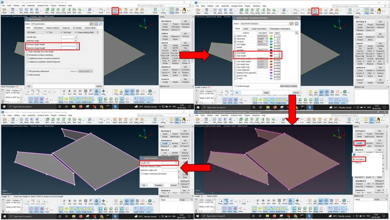
For meshing of Windows, we need to input mesh details at 4 places. For 1 mm mesh length,
Mesh parameters : min =4 & max =6. CFD, Tria, 1st order.
Quality criteria : min =4 & max =6.
Length > perimeters : target length = 5.
Length > macros : target length = 5.
For Length > perimeters & Length > macros we need to box select the geometry before input of target length.
Now, clicking on MESH GENERATION > SPOTMESH > VISIBLE creates mesh of 5 mm length over the Window region. Here we have taken min as 4 because of the smooth transition between the body of target length 4 mm.
Clicking on the HIDDEN option in view controls, shows OFF elements. We can right click and IMPROVE automatically or use SPLIT option when automatic improve fails on some elements. Ensure we have zero off elements at all stages of meshing. In general, we also allow 1% off elements.
After meshing the Window part, we shall use FREEZE option to freeze the mesh parameters and quality criteria of the window. So that while performing meshing in other PIDs, it won’t affect the window mesh.
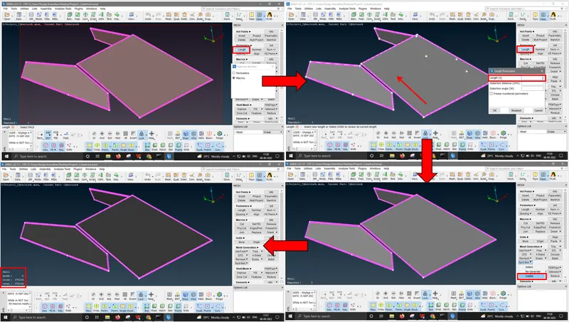
In a similar manner, we shall mesh other PIDs as well.
For meshing of Body, we need to input mesh details at 4 places. For 4 mm mesh length,
Mesh parameters : min =0.5 & max =5. CFD, Tria, 1st order.
Quality criteria : min =0.5 & max =5.
Length > perimeters : target length = 4.
Length > macros : target length = 4.
For Length > perimeters & Length > macros we need to box select the geometry before input of target length. We are using 0.5 as min value because of very small and sharp edges in the body, as this is a boxy design as well.
Now, clicking on MESH GENERATION > SPOTMESH > VISIBLE creates mesh of 4 mm length over the body region. we shall use FREEZE option here as well.
For meshing of Tyres, we need to input mesh details at 4 places. For 2 mm mesh length,
Mesh parameters : min =1 & max =3. CFD, Tria, 1st order.
Quality criteria : min =1 & max =3.
Length > perimeters : target length = 2.
Length > macros : target length = 2.
For Length > perimeters & Length > macros we need to box select the geometry before input of target length.
Now, clicking on MESH GENERATION > SPOTMESH > VISIBLE creates mesh of 2 mm length over the Tyres region. we shall use FREEZE option here as well.
We can use MEASURE tool to measure the mesh at all regions.
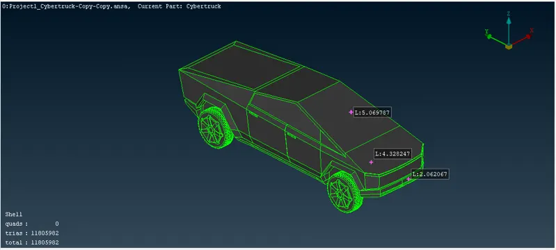
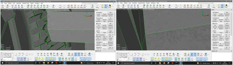
STEP 4: Computational Fluid Flow Domain creation and meshing
CREATING THE COMPUTATIONAL FLUID FLOW DOMAIN:
The general dimensional requisite for creating a computational fluid flow domain around a geometry is described in the image below.
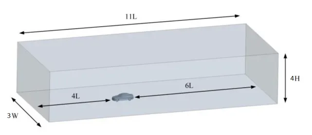
Here, L is length of the car, W is width of the car and H is height of the car.
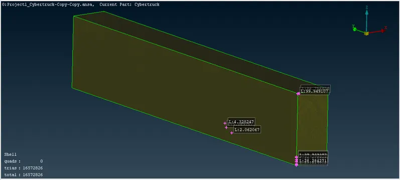
To create the computational fluid flow domain, we will create 3D points using RELATIVE method in TOPO module. From the floor of the car, we can select a hotpoint to create a 3D point relative. Our Tesla Cyber Truck dimensions can be measured using MEASURE tool and selecting nodes across the car, for simplicity purpose we can round off the values as well.
We shall consider L as 6000 mm, W as 2100 mm, H as 3200 mm. So the overall computational fluid flow domain size will be 66000 * 6500 * 12800. so, after creating 3D points we can use CREATE > CURVE option and connect all the 3D points so as to create the computational fluid flow domain. Then use FACES > NEW > COONS option to close all the faces. After this we will assign PIDs as top domain, bottom domain, side domain, front domain and rear domain.
MESHING OF COMPUTATIONAL FLUID FLOW DOMAIN:
We intend to create very fine mesh near the interface of flowing fluid and the car outer surface, so we can create fine mesh along the bottom part and coarse mesh along the top part of the computational fluid flow domain. We will consider 20 mm target length in bottom part and 100 mm target length in top part.
For meshing of Bottom domain, we need to input mesh details at 4 places. For 20 mm mesh length,
Mesh parameters : min =18 & max =22. CFD, Tria, 1st order.
Quality criteria : min =18 & max =22.
Length > perimeters : target length = 20.
Length > macros : target length = 20.
For Length > perimeters & Length > macros we need to box select the geometry before input of target length.
Now, clicking on MESH GENERATION > SPOTMESH > VISIBLE creates mesh of 20 mm length over the Bottom domain. we shall use FREEZE option here.
For meshing of Top domain, we need to input mesh details at 4 places. For 100 mm mesh length,
Mesh parameters : min =98 & max =102. CFD, Tria, 1st order.
Quality criteria : min =98 & max =102.
Length > perimeters : target length = 100.
Length > macros : target length = 100.
For Length > perimeters & Length > macros we need to box select the geometry before input of target length.
Now, clicking on MESH GENERATION > SPOTMESH > VISIBLE creates mesh of 100 mm length over the Top domain. we shall use FREEZE option here.
Since we want a gradual increase of mesh element from 20 mm to 100 mm from bottom to top domain, we shall use SPACING option in mesh module.
Factor shall be 1.1
Dmin shall be 20
Dlimit shall be 100
And select the four edges connecting the side domain with the front and rear domains.
For meshing of Side , front and rear domain using spacing, we need to input mesh details at 2 places. For gradual increase of mesh element from 20 mm to 100 mm length,
Mesh parameters : min =18 & max =102. CFD, Tria, 1st order.
Quality criteria : min =18 & max =102.
Now, clicking on MESH GENERATION > SPOTMESH > VISIBLE creates mesh that gradually increases from bottom to top, we can use MEASURE tool to verify. Now, unhiding all PIDs and use FREEZE option again with right click unfreezes all PIDs. There we have our Tesla Cyber Truck in a computational fluid flow domain.
Learning outcome:
- Working on the life size model is a good experience and gives a better perspective on how the software behaves.
- Meshing of such a boxy design puts a computational strain over the computer, so using various approaches to overcome it, is challenging.
- New experience on meshing a life size computational fluid flow domain.
Result:
Thus the geometry cleanup, surface meshing of Tesla Cyber Truck and creation & meshing of computational fluid flow domain is successfully completed with appropriate target mesh lengths.
Conclusion:
The overall process of geometry cleanup and surface meshing of the Tesla Cyber Truck was challenging in meshing part. The meshing part was challenging for the computational fluid flow domain as well, but using some alternate approach of meshing in parts and using freeze also reduced the computational time from hours to minutes. Hence, the Project 1: Surface Meshing of Tesla Cyber Truck is successfully completed & ANSA file is shared via gdrive link.
https://drive.google.com/file/d/1ejlp2PMDUy1TdH2TGWgdSR-7utxTDP52/view?usp=sharing