Week 4 Challenge : CFD Meshing for BMW car
Aim:
For the given model, check and solve all geometrical errors on half portion and Assign appropriate PIDs. Perform meshing with the given Target length and element Quality criteria. After meshing the half model, Do symmetry to the other side.
- Target lengths for the different parts of a model are as follow:
- Body - 3 mm
- Lights - 4 mm
- Grills - 1 mm
- Rims and Tyres - 2 mm
- Optical Rear view mirror - 2 mm
- Window - 2 mm
- Silencer - 3 mm
- Logo - 1 mm
- Solution:
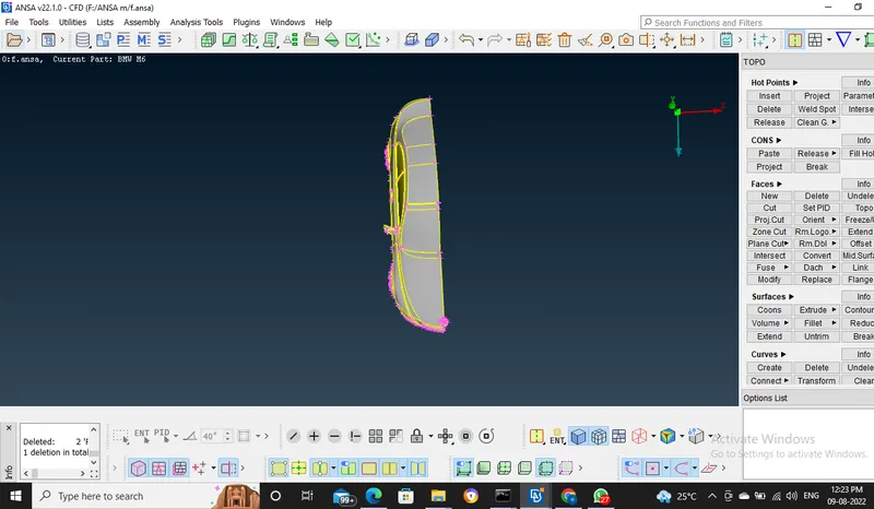
- first of all import the given geometry on ANSA The given geometry is symmetry so that's why we cut the whole geometry into two parts for convenience meshing.
- When the given car geometry is imported to ANSA, the small features of the car geometry are not captured accurately. This is because the mesh resolution is higher than some geometry features. To resolve this problem, Mesh> perimeters> length= 1mm
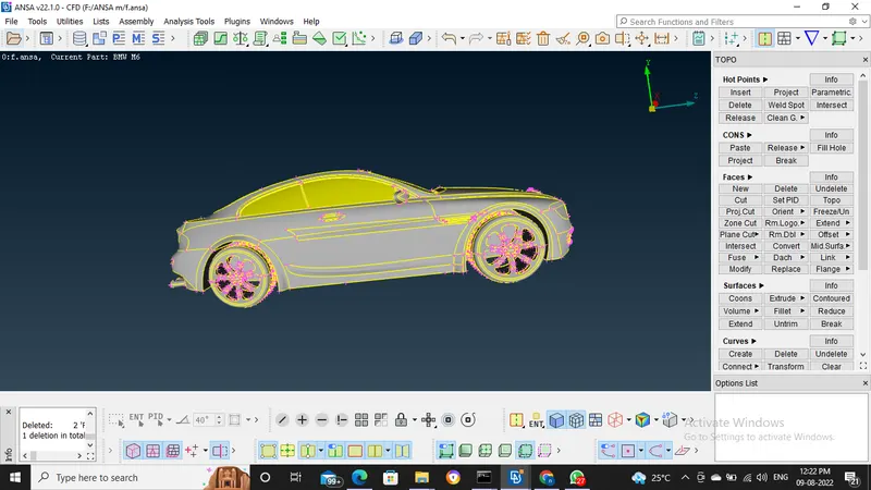
- The topo is cleaned by deleting unnecessary faces in the model, all triple cons are converted into double cones and single cones into double
- we have to clean every component one by one after that we have to assign the PIDs to every component
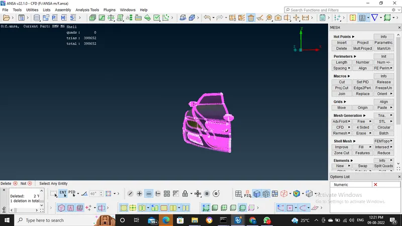
- Once all the geometric errors were resolved, the surface mesh is deployed on different car components with their respective mesh target lengths. In this problem, only triad elements are used.
- The surface mesh is first deployed on the smaller components, which are not in contact with other parts/PIDs, then it is done on the remaining components.
- Once all the surfaces have meshed, we must check whether or not the generated mesh satisfies the mesh quality criteria or not. If not then the surface mesh must be reconstructed. For the mesh quality criteria for the car components
- according to the quality we have to change the range of parameters.
- then cfd mesh are generated by using the cfd meshing command.
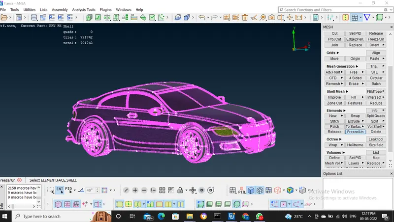
- the mesh is generated on all the regions of the car model, we can now generate the complete car model. This is done by the use of the symmetry option. Transform> copy> entities> symmetry> mirror 3 point plane, then select any 3 points on the symmetric plane.
- Then, all the entities will get copied to the other side of the symmetric plane. The geometry show some single cons once this is done, this can be rectified by performing topological checks. Topo> faces> topo
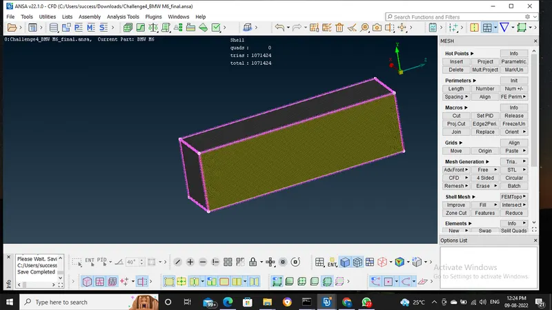
- then the car geometry must be enclosed in a box (virtual wind tunnel) to perform external aerodynamic simulations. If the length of the car is 'L' meters then, the virtual wind tunnel dimensions are as follows:
-
Distance from the wind tunnel inlet to the front of the car= 4x
Distance from the aft of the car to the wind tunnel outlet= 6x
Distance from the sides of the car to its respective wind tunnel sides= x
Distance from the floor to the top surface of the wind tunnel= 3x
- Now a surface mesh must be generated on the wind tunnel surface. Since we want finer volume mesh near the surface of the car, which is resting on the floor of the wind tunnel
- To achieve this first the wind tunnel floor and top surfaces are meshed separately with triad mesh elements and the mesh target length of 20mm and 100mm respectively.
- after that to mesh the other faces in a gradually increasing manner, go to mesh> perimeters> spacing, select the 4 edges, take biasing as geometric (1.1), and dmin= 20, dlimit= 100.
- Then, the geometry using spot mesh, and check for quality criteria errors if any. If there are any errors, it can be rectified mesh> shell mesh> reconstruct.
- after that surface mesh is generated on all the components, the volumetric mesh can be created. In volume mesh> define> auto-detect> whole database.
- then delete all the unwanted components, ie, the volumes enclosed by the solid surfaces
- then right-click on the fluid volume detected and click on re-mesh using tetra CFD mesh, and the required mesh will be generated.
Drive link of model:
https://drive.google.com/file/d/10lVaYCvbB_mvw3He1m1xipdgEIb4vj3m/view?usp=sharing