Week 3 Challenge : CFD meshing on Turbocharger
AIM: For the given model, check for the geometrical errors to make appropriate volumes. Create and assign PIDs. Perform surface mesh with the given target lengths as per PIDs
- Blade stage-1 = 1 mm
- Blade stage-2 = 1 mm
- Impeller = 2 mm
- Shaft rotor = 1 mm
- Turbo casing = 5 mm
- Compressor casing = 5 mm
- Inlet casing cover = 5 mm
Perform Volumetric mesh for the required volumes as shown in the videos.
Write a detailed report on your surface meshing & Volume meshing process.
PROCEDURE:
-
First of all, we open the ansa file of the turbocharger in the ASA software then we have to clear all the errors, there are many cracks, and glitches in the diagram of the turbocharger so we clear all the unwanted components and the hot points and the coons.
- then we varify the whole model by using the geometry check command and we found some errors are there, like triple coons the single coons
- we resolved all that errors and again check in the geometry check so we found our diagram is neat and clean
- The next phase is to assign the PIDs. this is used to differentiate each component with the different names and colors, so that's why we assign every ent into PIDs to make our work easy
- then after creating the PIDs, we have to combine all PIDs for the surface meshing
- then we went to the mesh interface and mesh every single component of the turbo charger as the given target of length and macros.
- after completing the surface mesh next to doing the volume mesh, we clicked the v-mesh option, then we have to define the volume to be meshed by clicking the Define option in the volume.
- then we get the list of unmeshed components in the v_mesh interface
- we have to rectify it and we delete some parts because they are unwanted.
- we select the volumes which suit those and remove remaining
- then in the next step various types of volume Meshes are shown in the Unstructured Mesh Section, from which a required type of Volume Mesh is selected. Here, we need to do a Mesh for CFD Analysis, so we choose the Mesh option Tetra CFD. Then select the whole component and press the middle click button on the mouse to perform Volume Mesh
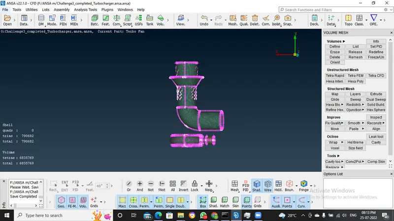
- After Volumetric Mesh is done, let's examine the meshing by removing some parts in the Meshing. In this, we can see that in the boundaries of components such as turbine impeller, compressor two stage blades, and compressor casing there was the coarse mesh, and in the surfaces away from these boundaries, we have very fine meshing. and CFD meshing is done successfully.
Drive link : https://drive.google.com/file/d/1dG27LTyLqjYtxgIAksH7TLDwcQp0xJ3-/view?usp=sharing