Week 4 Challenge : CFD Meshing for BMW car
TITLE : - CFD meshing of BMW car
Aim : - To perform CFD meshing with given target lengths on BMW car model.
Problem Statement : -
For the given model, it is required to check and solve all geometrical errors on half portion of the car and to assign appropriate PIDs. Further, it is required to perform meshing with the given target length and element quality criteria. After meshing the half model, do the symmetry to the other side.
Target lengths for the different parts of a model are as follow:
- Body - 3 mm
- Lights - 4 mm
- Grills - 1 mm
- Rims and Tyres - 2 mm
- Optical Rear view mirror - 2 mm
- Window - 2 mm
- Silencer - 3 mm
- Logo - 1 mm
Procedure : -
For the given model, geometric cleanup is to be done so that it is possible to create the required volumes for volumetric mesh. Thus for given geometrical model, it is required initially to do geometrical cleanup.
GEOMETRY CLEANUP
1. Import the model into the ANSA software. Then change the view mode from ENT to PID. Thus all the CONS are visible. As single CONS are present, use TOPO in faces and select the complete model and confirm. This will convert maximum possible single CONS into double and triple CONS.

Figure 1:- Model import and using TOPO to convert maximum possible single CONS to double and triple CONS
2. It can be observed that the model has some shapes to be irregular, thus CONS resolution is to be increased. Switch the mode from TOPO to Mesh, perimeters> Length> Perimeter> Select whole model> Length= 1; and same for macros. This will fine the model properly. CONS resolution is increased to fine the faces of model. Again switch the mode from Mesh to TOPO. Thus it can be observed that the model is now proper (fine model).
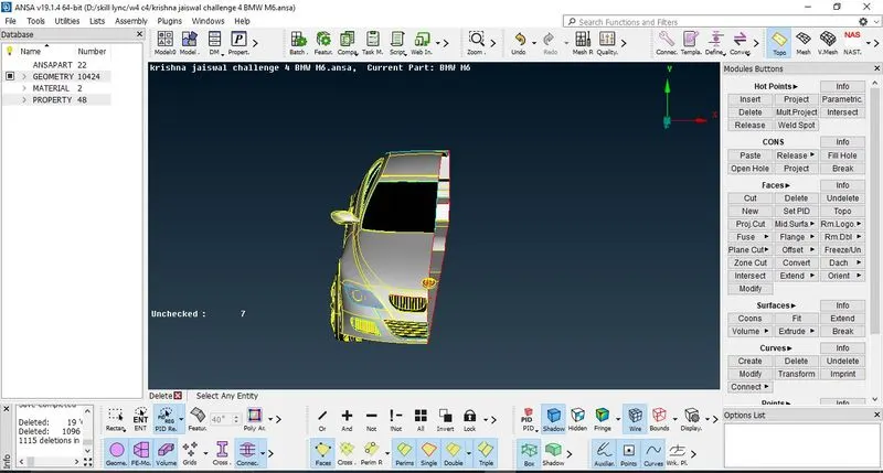
Figure 2 : - Model is fined properly and half model symetrically is deleted (excluding the logo)
3. As the BMW car is a symmetric model, thus it is possible to perform cleanups and meshing on one side and reflect the same on the other side. Thus here delete half of the model symmetrically. Keep the symbol of car as it is not symmetrical.
4. As the inside surfaces are not necessary since the wind tunnel and the flow will be at the outer feature of car model, thus initially geometrical cleanup must be done.
5. Delete the inside surfaces of model to remove the triple CONS. Now use paste option to join single CONS so that it will form double CONS. Delete overlapped surfaces and unnecessary surfaces so that maximum of triple CONS are removed. 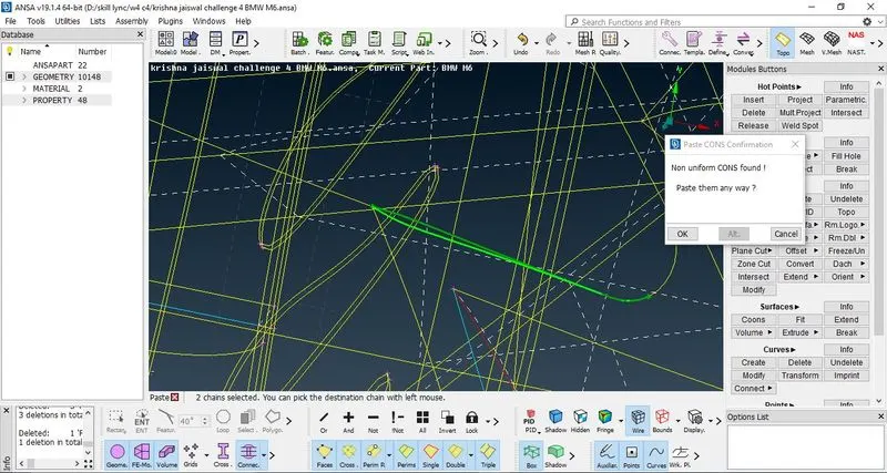
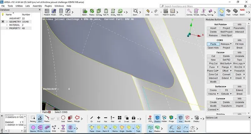
Figure 3: - Using paste option to join two single CONS to form double CONS
6. Use I-Not option to isolate the surfaces on which topology cleanup is to be performed step by step. Lock the view so that only required geometry is visible and cleanup can be performed. Now delete the unnecessary hot points, then project the Single CONS onto the face and then delete the unnecessary surface, then use TOPO to make single CONS into double CONS.
7. Try to Delete the surfaces which are not patched thus deleting and then creating new faces with PID definition will allow to make surfaces proper and single CONS will be removed.
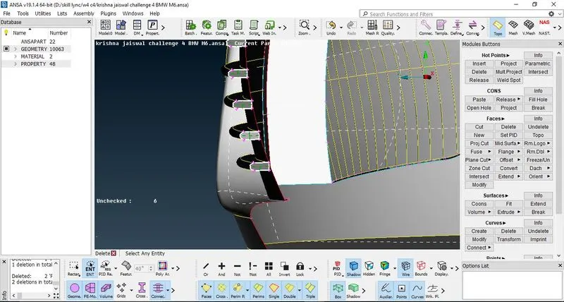
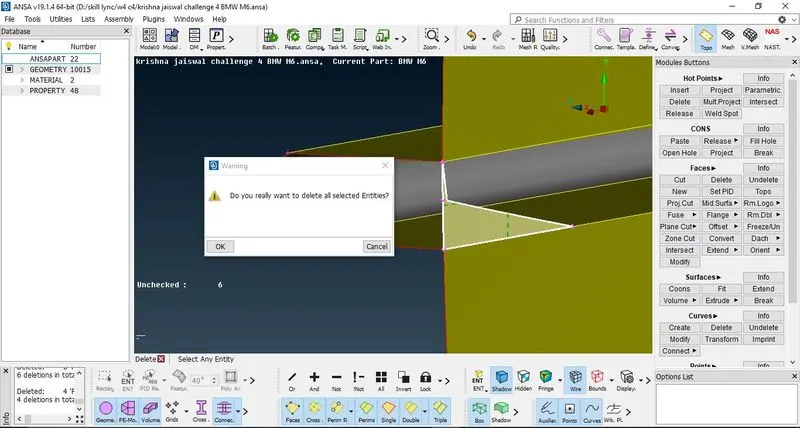
Figure 4: - Deleting the unnecessary surfaces step by step and performing cut and release opertaion so as to delete the required surface only
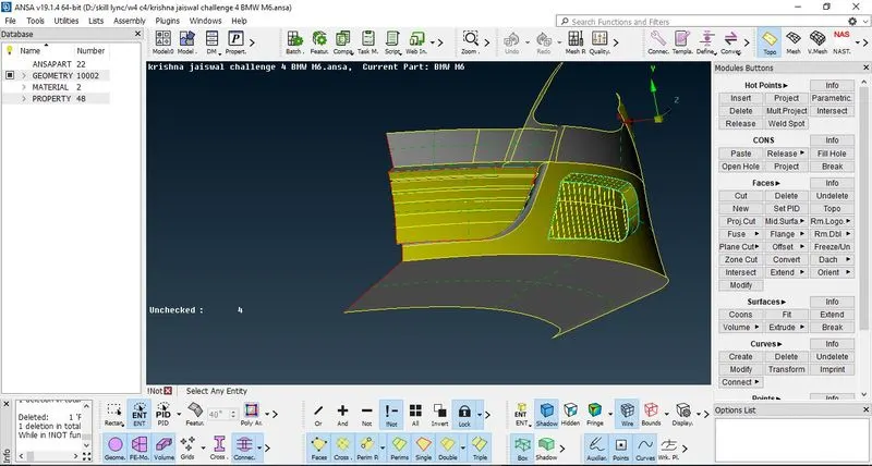
Figure 5: - Using the I-Not option in the focus menu to isolate the grills on which geometric cleanup is to be performed
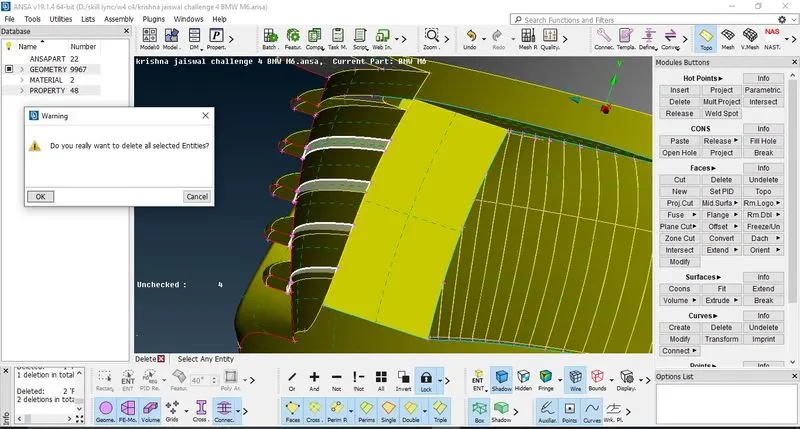
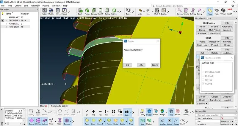
Figure 6: - Deleting the unnecessary surfaces and creation of new surfaces
8. Use project option in CONS to project the single CONS over the surface.
9. Now use the EXTEND option to extend the surfaces (this option is only good when worked on SINGLE CONS>select single cons> then select the target face on which surfaces is to be extended> press scroll to confirm. This will extend the CONS which are to be joined.
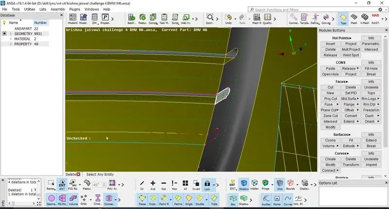
Figure 7:- Projecting CONS over the face
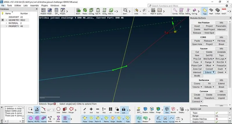
Figure 8:- Use of Extend option to extend the CONS on the surface to join them
10. Now further, release the CONS and try to fix the single CONS by creating the hot points and then performing the operation. Faces> Topo. Thus all the single CONS are removed and only double CONS are present.
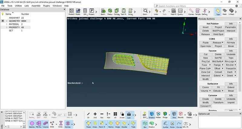
Figure 9: - Isolating the grills and ribs (geometrical cleanup done on grills)
Thus this completes the cleanup of Grills and headlights of BMW model. Now turn off the LOCK view and click on ALL to see the complete half model of car.
11. Now we again use the I-Not option to isolate the second grills so that geometric cleanup is to be performed. Then Lock the view.
12. It is observed that the presence of triple CONS which will create unnecessary volumes is to be removed so that the whole grill remains a single volume. For this delete the unnecessary surfaces.
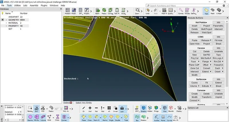
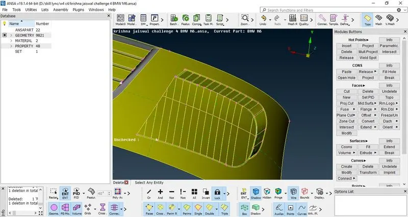
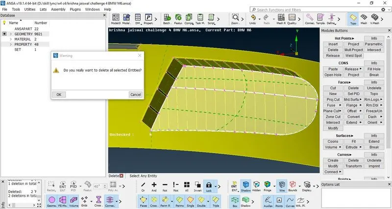
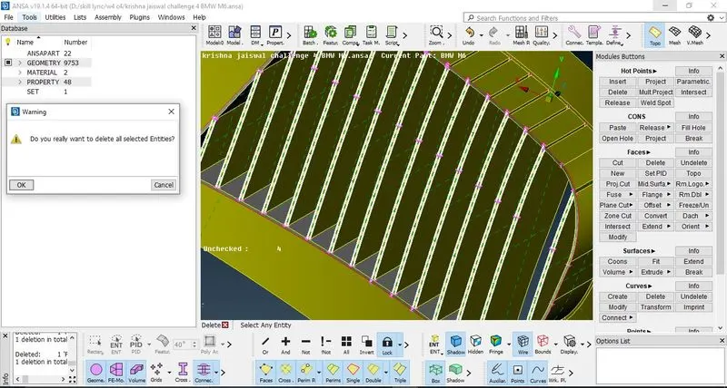
Figure 10: - Deleting unnecessary surfaces
13. Now the ribs (grill lines) are to be made proper such that this all forms a single volume, so delete the surfaces, then delete the inner thin faces of grills, check whether the ribs are in proper aligned, create cuts by faces> cut> make the cut from one hot point to another at bottom end of ribs (grills)> press scroll to confirm. Then delete the irregular unwanted surfaces.
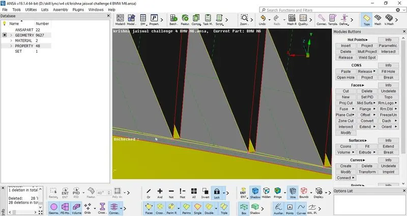
Figure 11: - Making a proper Cut
14. Now delete the surfaces as shown in figure 12 and 13. Now patch the surface by using CONS> Fill hole > select the surface to be patched> OK to Confirm.
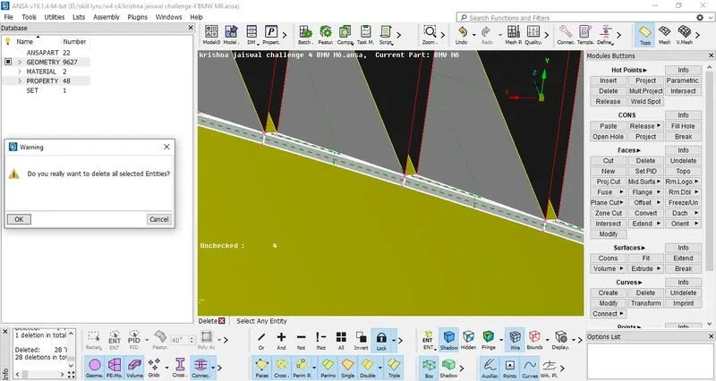
Figure 12: - Deleting the surfaces
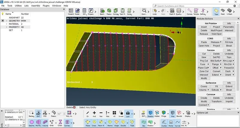
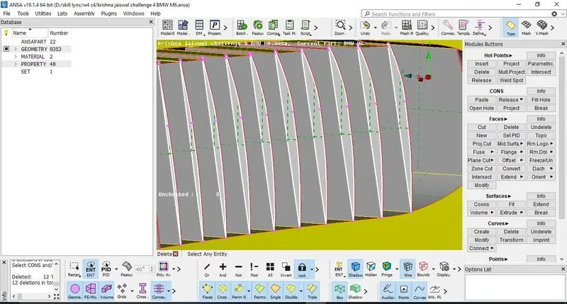
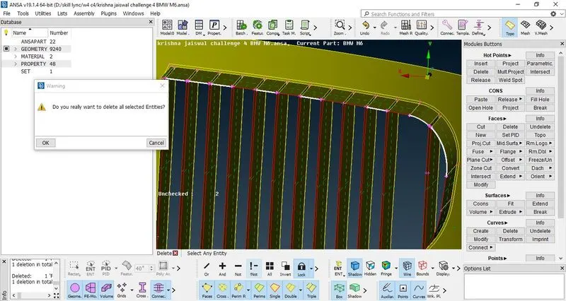
Figure 13: - Deleting unwanted surfaces to create single volume
15. Now use cut option to make the ribs faces in regular shape so that fill hole option is possible to be used and thus to create a single volume. After making the cut, delete the unnecessary surfaces. Use fill hole option or either create new faces such that the single CONS are completely removed.
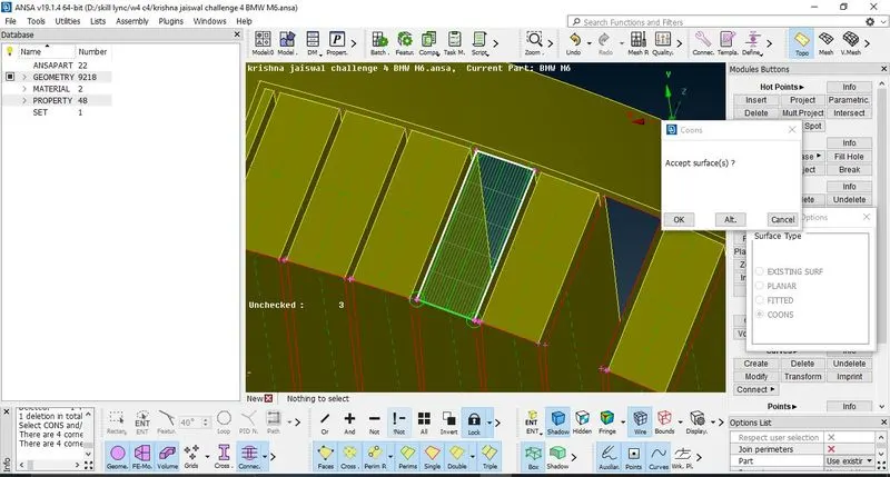
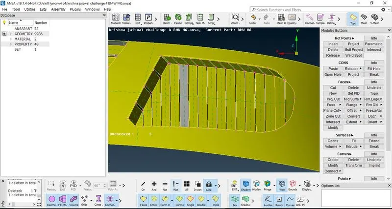
Figure 14: - Creating new surfaces and using fill hole option
This completes the geometric cleanup of ribs and grills. Always perform geometric checks to know whether the triple or single CONS or sharp edges are left. As geometry check is completed and no errors were found. (exclude the Concave and mixed CONS)
16. Now isolate the logo using I-Not option in order to perform geometric cleanup on logo.
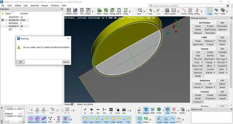
Figure 15: - Deletion of unnecessary surface of logo
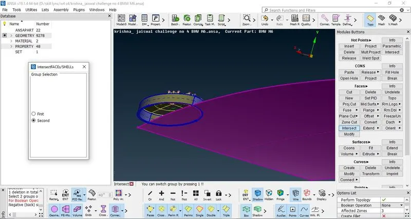
Figure 16: - Using intersect option to intersect the logo and hood of car model
17. Delete the overlapped unrequired surfaces. Then intersect the surfaces and then delete the unnecessary surfaces created, then extend the single CONS over the hood surface so that it will form triple CONS.
18. Now delete the surfaces overlapped so that only double CONS are present, then create new surfaces where gaps are present in the logo so as to remove the single CONS.
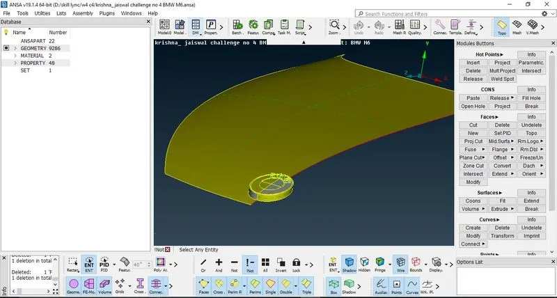
Figure 17: - Completion of geometric cleanup of logo
19. This completes the geometric cleanup of logo, now click on ALL to see the complete half model, try to delete the triple CONS (overlapping surfaces) in the model. Thus maximum of triple CONS are removed.
Now to perform geometry cleanup of remaining grills
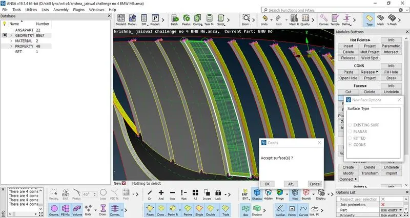
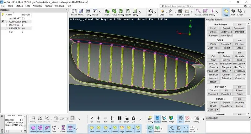
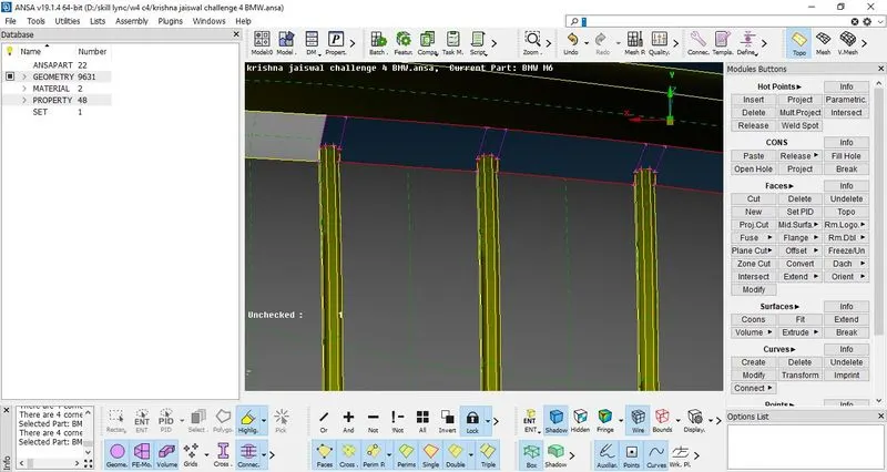
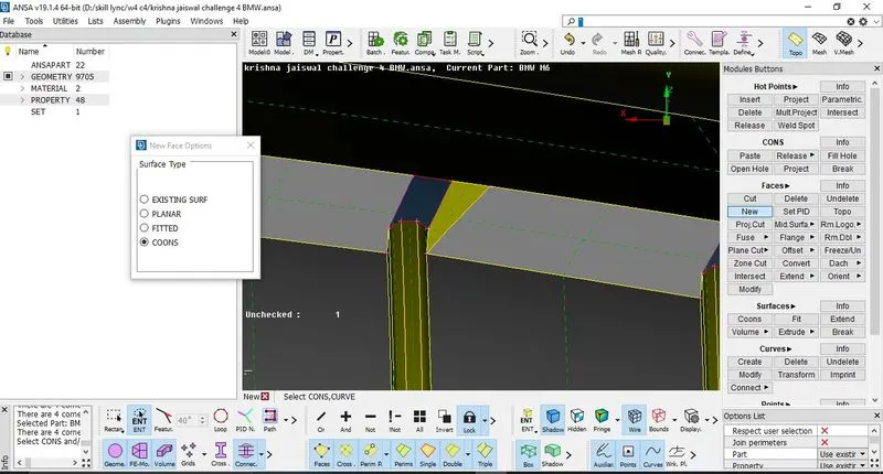
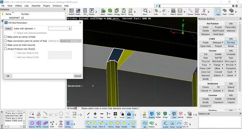
Figure 18: - Performing geometric cleanup on remaining grills (new face creation, plane cut, adding new curves, creating new faces to join top ends, using fill hole option)
20. Then for remaining grills remove the single CONS by making a plane cut at the top surface which is not required, then do the same procedure of making cut and deleting as done for other grills, further create new surfaces in gaps of two ribs.
21. Then use Multi-project option in hot points to project the hot points from the surface, create new lines as shown in figure by Curves> Create > Select two hot points> press scroll to confirm. Then fill the surfaces using fill hole option or making new faces in Faces> New> Coons> selection of CONS> Ok to Confirm.
Thus this completes the geometric cleanup of logo, ribs and grills of BMW car model. Now to work on other remaining surfaces, perform the geometric cleanup as follows: -
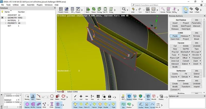
Figure 19: - Geometric cleanup on remaining surfaces of car model
22. The figure depicts that there is no intersection between the surfaces since triple CONS were expected but are not present, so make an intersection between the surfaces, use faces> Intersect> 1st group selection> press scroll to confirm> 2nd group selection> press scroll to confirm. Thus the required surfaces are made intersect.
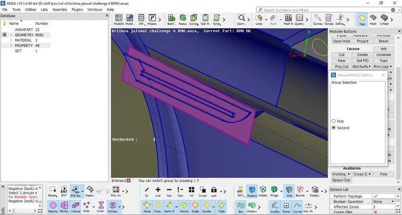
Figure 20: - Intersecting the two surfaces by using intersect option
23. Delete the unnecessary surfaces in order to form a single volume only. Then extend the single CONS to the surfaces so that the surfaces are connected and forms triple CONS.
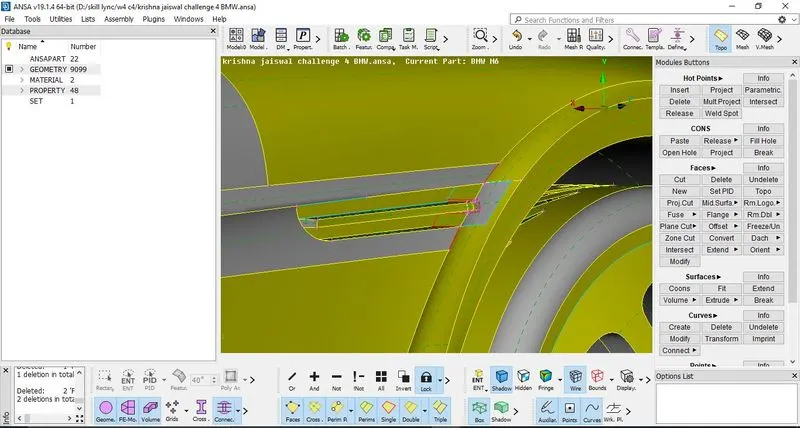
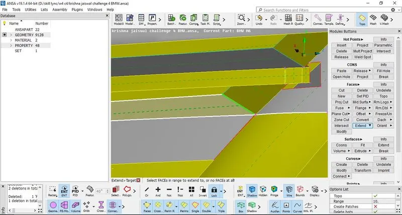
Figure 21: - Extending the single CONS over the surface
24. Make a cut and then delete the unnecessary surfaces. Further create new surfaces so that the triple CONS and single CONS are removed and only double CONS are remained. This is done so that there must not be new different volume created other than the single volume of body of car. Few triple CONS are present at the border so it is possible that it can be deleted directly as there is only very small unnecessary surface created.
25. After completing geometric cleanup over the region, remove the lock view and click on ALL to see all the surfcaes of the model. Now it can be seen that geometric cleanup of side mirror is remaining, isolate the side mirror surfaces using I-Not option in the focus menu.
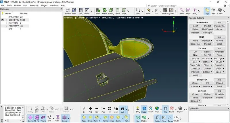
Figure 22:- Isolating side mirror in order to perform geometric cleanup
26. Hide the surface using Not option, then delete the surfaces with triple CONS present, make a geometry check. Thus triple CONS are removed and only double CONS are present. Remove the lock view and click on ALL to see complete half model of car. Now from the interior, it can be observed that side mirror and remaining model must be a single volume, so delete the surface, create a new surface at the same location, intersect the side mirror onto that surface using intersect option, delete the unnecessary surface, thus this forms a single volume of side mirror and remaining body.
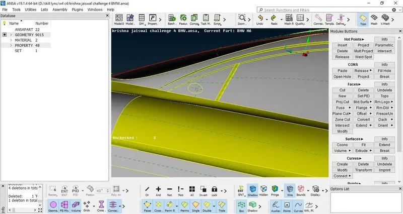
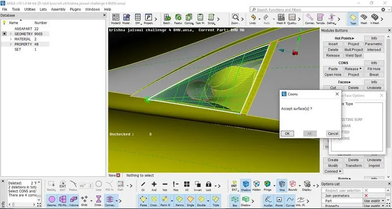
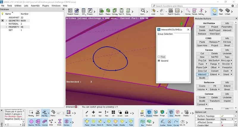
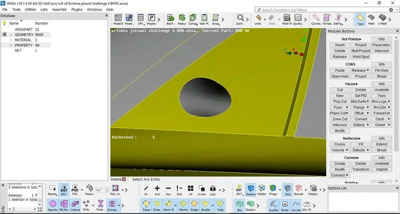
Figure 23: - Geometric cleanup to make side mirror and remaining body as single volume
27. After this, now geometric cleanup of tyres is to be done. Starting with front tire, isolate the front tire.
28. After Isolating the tire, lock the view, then hide the surface using not option, then delete the unnecessary surface, and then click on ALL to see the complete view of tire. Also delete the surface shown in figure, now as triple CONS are removed, there will be only single volume.
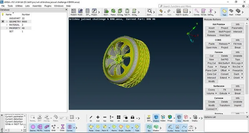
Figure 24 : - Isolating the tire to perform geometric cleanup
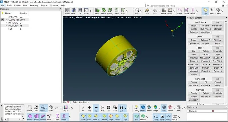
Figrue 25: - Using Not option to hide the surface
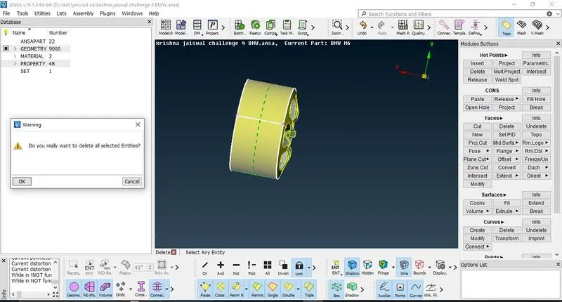
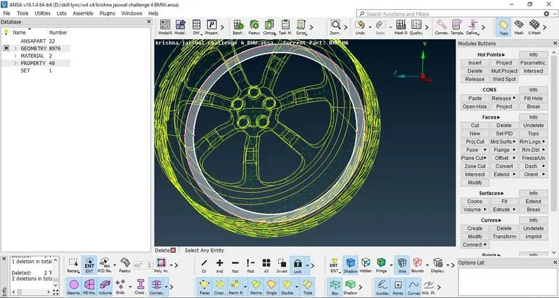
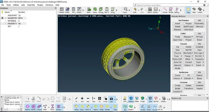
Figure 26 :- Deleting the unnecessary surfaces and then creating new surface to form double CONS
29. Thus proceed with same procedure for another tire.
30. Always perform geometric checks to check whether any single or triple CONS are present. If present, try resolving it. After the geometric check is done, further complete the geometric cleanup for remaining regions of car model.
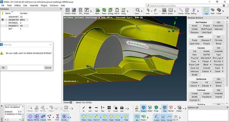
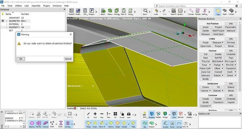
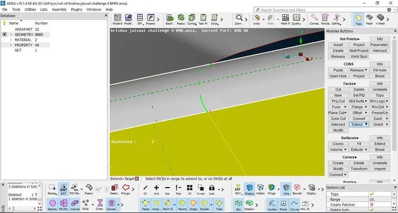
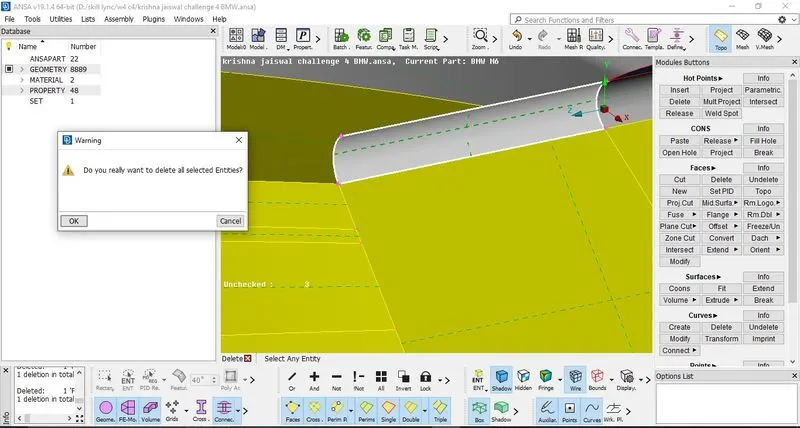
Figure 27: - Performing geometric cleanup on remaining regions of model
31. Then perform the geometric cleanup on remaining surfaces.
32. Now at the base, it can be observed that there are unnecessary surfaces present which is to be removed, perform geometric cleanup by deleting the unnecessary surface so that intersections which are unnecessary are removed. Use Cons2Curves option in the curves menu so that it will create curves for the reference. After deleting the surfaces, start creating new faces with inserting new hot points whenever needed. Then further after completing the creation of faces at the base, delete the curves created due to Cons2Curves option.
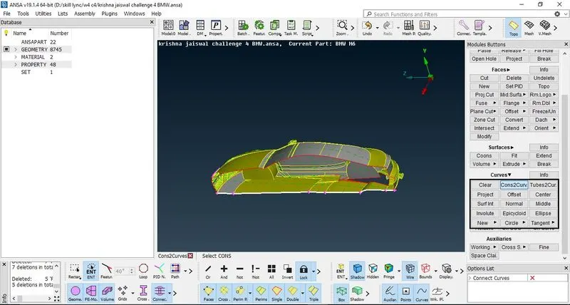
Figrue 28: - Using Cons2Curve option to keep the curves as references
33. Perform geometry check and intersection check. To perform inetrsection check, Checks> penetraion> intersection> Execute. Thus it will show the locations of intersections. Try deleting the intersection surfaces and create a surface at the same location to resolve the error.
34. Perform a final geometry check with checks manager.
As there are no errors, this completes the geometrical cleanup of the BMW car model.
Surface Meshing
1. Now to perform surface mesh initially, define the PID’s so that the name and property definition is done for the model and as per the given target length, the meshing can be done.
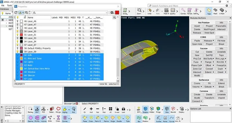
Figure 29: - Defining the PID's in Property manager (PID Manager)
2. Initially name define the name of PID’s in property manager. Properties> right click to view all option> new> PSHELL>PSHELL> define the name> Ok to confirm. Thus all the names were defined in PID manager.
3. Now define the PID’s one by one by isolating the surfaces and then applying the PID’s. For example, to apply PID of rims and tyres, isolate the rims and tyres surfaces using I-Not option, then go to PID manager> right click over the name of PID (here it will be rims and tyres) > Apply> select the surfaces> Press Scroll to Confirm.

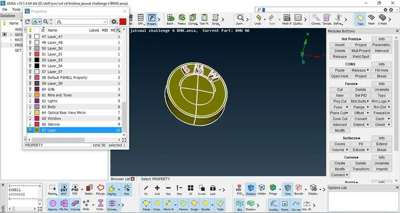
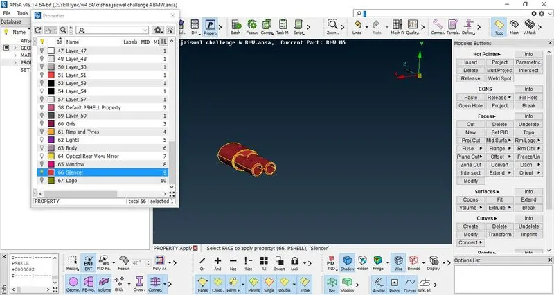
Figure 30: - Applying PID's to the model (figures for reference Logo, Silencer,Grills)
4. Thus follow the same procedure to apply the required PID’s. Now further to cross check, switch from ENT mode to PID mode. Then it can be observed that the required PID’s are properly defined. Then delete the unnecessary PID’s using Compress option. Now only 8 PID’s which are required will be seen in PID manager.
5. Now before starting with mesh, go to quality criteria, hide the unnecessary criteria’s and keep only max length, min length and skewness. Then turn ON the hidden option to see the quality criteria. Define different colors for different criteria.
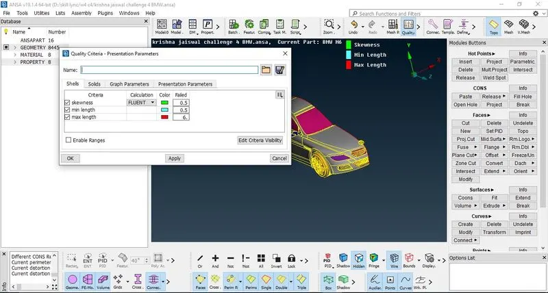
Figure 31: - Enabling the required Quality Criteria
6. Give the min length as 0.5 and max length as 6, since the minimum and maximum target length for the complete model are 1 and 4mm respectively. Thus we define the minimum and maximum length to be lower and higher than actual lengths respectively.
7. Starting the meshing as follows with target length for the PID’s,
Grills and Logo – 1mm
a) In the PID manager (property manager) isolate the grills and logo. Then switch the mode from TOPO to MESH. Go to Mesh Parameters> Change the element shape from mixed to tria, change the target length from average to 1mm, change the minimum target length as 0.5 and maximum target length as 1.5. Then Ok to confirm.
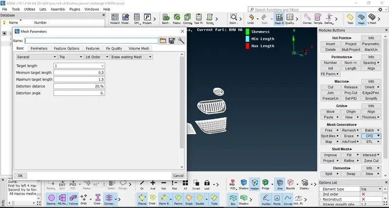
Figure 32: - Defining Mesh parameters for grills and logo
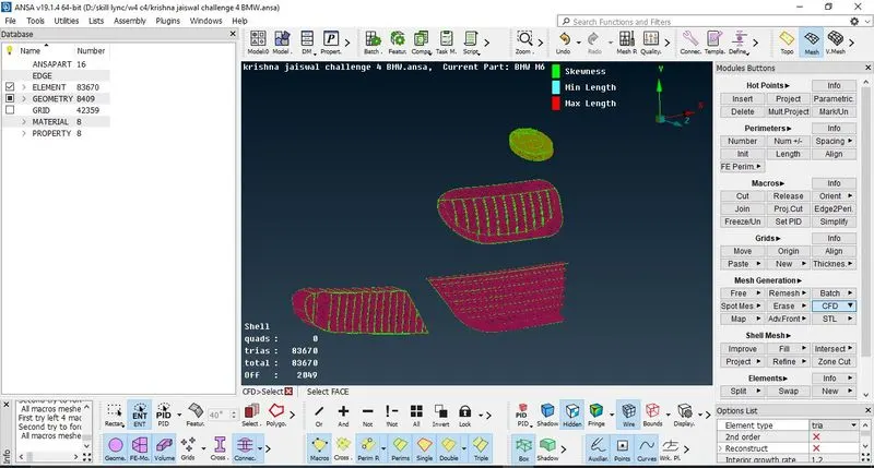
Figure 33:- Performing surface mesh (Last row shows the number of offset elements that is to be resolved)
b) Further perimeters> Length> perimeters> select the grills and logo> give value as 1> macros> select the grills and logo> value=1> ok to confirm. Then to perform mesh, Mesh generation> CFD> Select the grills and logo> Scroll to confirm
c) This completes the surface mesh of grills and logo. Now it can be observed that the offset value comes to be a very large number.
Offset is that elements in meshing that has not cleared the quality criteria and must be improvised.
d) So it can be done by right click on offset > Improve > do the improvisation for the elements by selecting reconstruct or reshape or any other option. Do this step multiple times so that the offset is removed. If the number of offset is low and improve option doesn't resolve, then use Move option and split option in order to move and split the cells so that offset is removed.
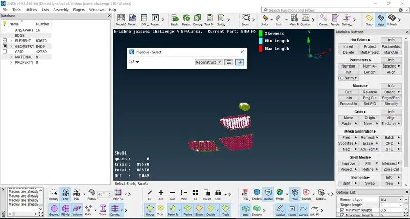
Figure 34: - Improvising the offset cells
e) Thus as offset is removed, freeze the macros by Macros> Freeze> select the grills and logos with zero offset> press scroll to confirm. This will freeze the macros for grills and logo.
Repeat the same procedure as done in grills and logos for the following: -
|
Sr.No |
PID name |
Target Length |
Minimum Target Length |
Maximum Target Length |
Element Type |
|
2. |
Rims and Tyres |
2mm |
1.5mm |
2.5mm |
Tria |
|
3. |
Windows |
2mm |
1.5mm |
2.5mm |
Tria |
|
4. |
Optical Rear View Mirror |
2mm |
1.5mm |
2.5mm |
Tria |
|
5. |
Lights |
4mm |
3.5mm |
4.5mm |
Tria |
|
6. |
Body |
3mm |
2.5mm |
3.5mm |
Tria |
|
7. |
Silencer |
3mm |
2.5mm |
3.5mm |
Tria |
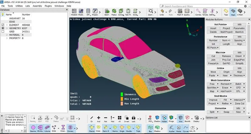
Figure 35: - Surface meshing done with tria elements and zero offset elements
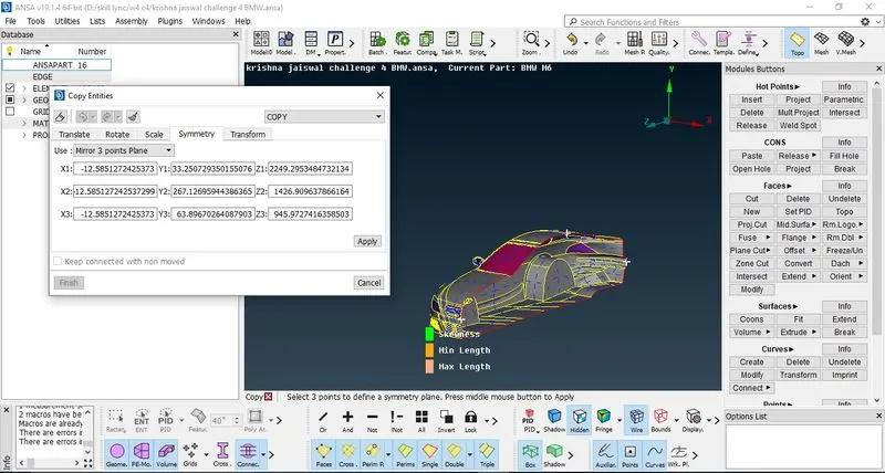
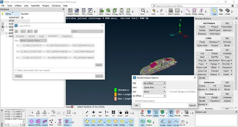
Figure 36: - Making the complete model of car (copy and symmetry)
8. After completing the surface mesh with removal of offset, it is required to turn the half model of car into full complete model. Before using symmetry make sure that the logo is not symmetrical thus must be made hidden using NOT option.
9. This can be done by using Transform>Copy>Symmetry> Select the entities> 3 Point Plane> select the 3 points where the same mirror of model is to be made up> Transformation option>Ok to Confirm.
10. This will create the complete model of car, to remove single CONS use TOPO. If two single CONS are there one above another, use paste option.
This completes the creation and surface meshing with zero offsets of car model.
Now to perform the CFD simulations, Wind tunnel is to be created.
Creation of wind tunnel
1. To create a wind tunnel,
- From the front face of the car that is from the grills or bonnet, the minimum distance must be 4*Length of Car.
- From the rear deck or silencer or taillights, the minimum distance must be 6*Length of car
- From the top face of car, the minimum distance must be 3*Length of car
- From the side faces of car, the minimum distance must be Length of car
- From the bottom face of car, the bottom face of wind tunnel and tyres of car must not be intersecting.
2. Measure the length of car.
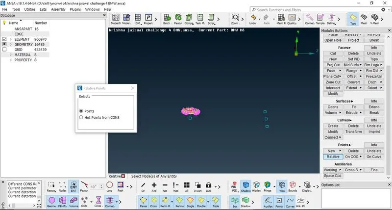
Figure 37: - Creation of new points to create the wind tunnel
Length of car = 1303.6, so we take the value to be more than 1303.6.
Here we take the length to be 1305 so that wind tunnel is created in proper way and is better for CFD simulation purpose.
3. Create new points as per the calculated distances, then from that points, create new curves from curves menu, join the curves one by one, then create the faces by selecting the curves. Thus this creates the wind tunnel. Distances from the car model: -
Distance from the front face = 4*1305 = 5220
Distance from the rear face = 6*1305= 7830
Distance from the side faces = 1305
Distance from bottom = 500
Distance from top face= 3*1305 = 3915
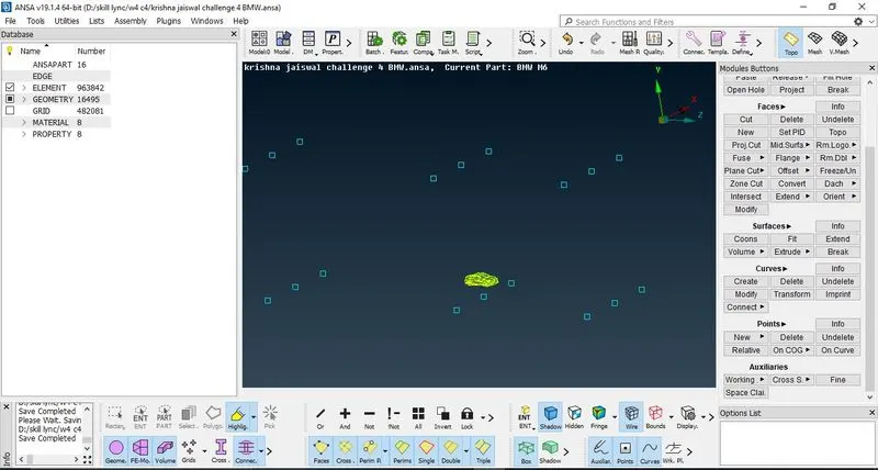
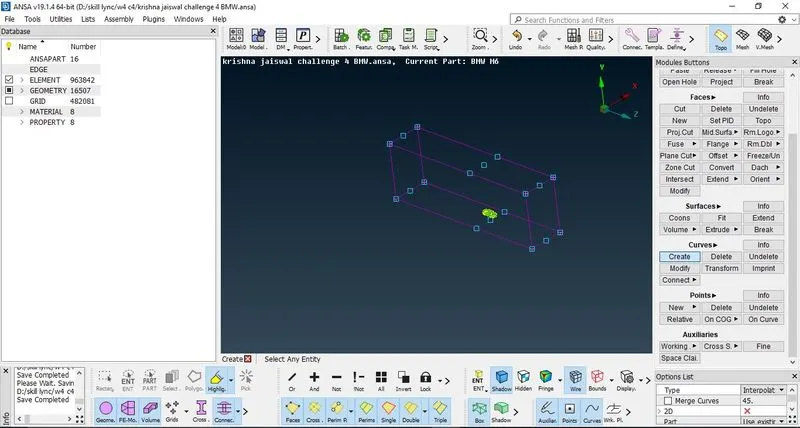
Figure 38: - Creating the wind tunnel
4. After creating the complete wind tunnel delete the unnecessary points and curves and perform TOPO if single CONS are present for the wind tunnel.
5. Now to create surface mesh on the wind tunnel:
a) Create new PID's and define the PID's to wind tunnel: - top face, bottom face and side face
b) Then isolate only the bottom face for surface mesh. Go to mesh parameters> CFD mesh> Minimum target length= 10; maximim target length =30> Ok to confirm.
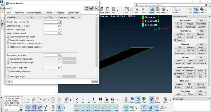
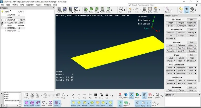
Figure 39: Performing mesh on the bottom face of wind tunnel
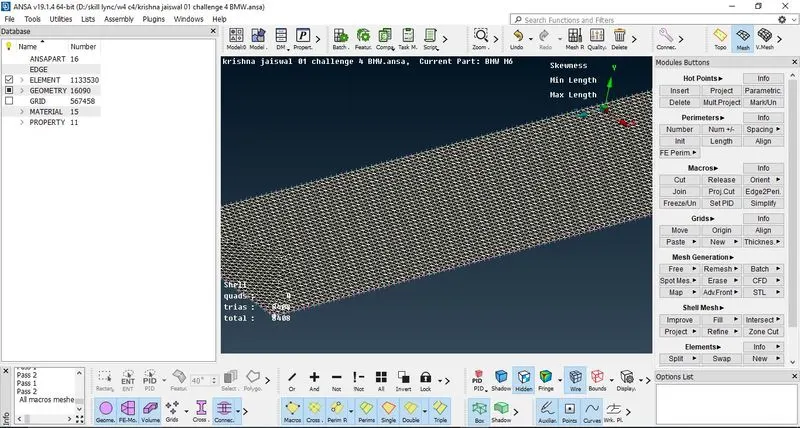
Figure 40: - Meshing the Top Face of wind tunnel
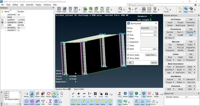
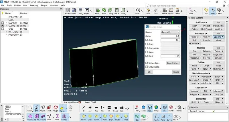
Figure 41: - Performing growing mesh on side faces of wind tunnel
c) Then go to perimeters> Spacing> AutoCFD> Give the perimeters and macros> Select the bottom face > Ok to confirm.
d) Then generate the mesh by Mesh Generation> CFD> Visible. This will create surface mesh on bottom face of wind tunnel.
e) Repeat the procedure for the top face with minimum target length=90 and maximum target length=110.
f) For the side faces of wind tunnel, enable the visibility of all the faces of wind tunnel only, then to create mesh with growth from bottom face to top face, go to perimeters> Spacing> Manual> give the limits as dmin= 20 and dlimit=100> select the edges of side faces of wind tunnel with direction pointing from bottom to top> Ok to Confirm.
g) Generate the mesh with same procedure as defined in step (d).
Thus it can be observed a growing mesh over the side faces of wind tunnel from bottom to top.
Thus this completes the meshing of BMW model car with wind tunnel surface mesh.
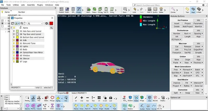
Figure 42: - Complete surface mesh of BMW car with zero offset elements
Result: - This completes the surface meshing of BMW car with creation of wind tunnel with proper target lengths and zero offset.
Learning Outcomes: - Proper CFD meshing with geometric cleanup and learning various options to perform cleanup and meshing of the given model with defining the quality criteria and improvising the mesh accordingly so that no offset elements are present, moreover learning how to create a wind tunnel for given model.
Link to download the model: -
https://drive.google.com/file/d/1sUNzmDcpzOz7NCnnAawxQin1TSybOO0T/view?usp=share_link