Week 3 Challenge : CFD meshing on Turbocharger
Aim:- CFD Meshing on Turbocharger
Problem Statement: - To perform meshing on turbocharger model with correction of geometrical errors and assigning the PID’s for different parts of the given model. Details of target lengths for different PID’s are as follows:
1) Blade stage – 1 = 1mm
2) Blade stage – 2 = 1mm
3) Impeller = 2mm
4) Shaft rotor = 1mm
5) Turbo casing = 5mm
6) Compressor Casing = 5mm
7) Inlet casing cover = 5mm
To perform surface meshing and volumetric meshing on the turbocharger model.
Procedure: - Initially first perform the geometric checks and carry out the topological cleanup.
1. Import the .ansa file into the ANSA Software.The model will be displayed, change the view mode from ENT to PID, the model imported is shown in figure 1.
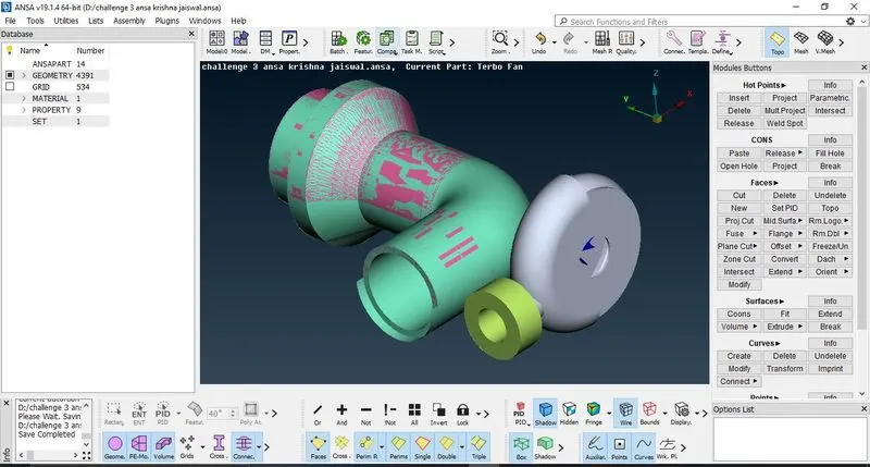 Figure 1: ANSA Model import in the software (Turbocharger model)
2. Delete the overlapped surfaces by delete > select overlapped cross hatch> OK to confirm (figure 2).Now to make the face proper delete the improper face as shown in figure and then create a new face by clicking on Faces> New> Fitted> selection of edges> OK to Confirm. This will create the face required. (figure 3) 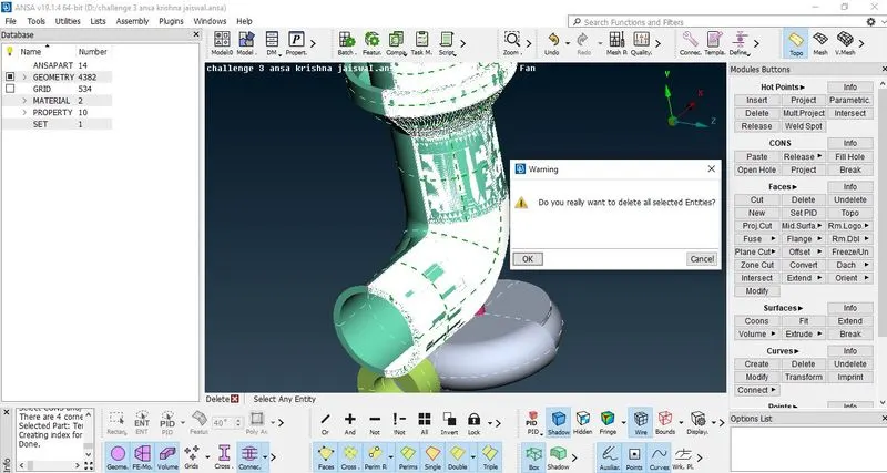
Figure 2: Deleting overlapped surface (unnecessary surface)
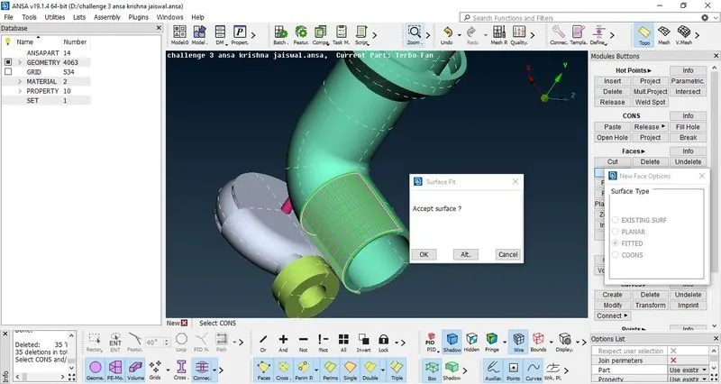
Figure 3: New face created
3. It is necessary to remove the single CONS present in the model. Check for single and triple CONS present in the model. Now as shown in figure 4, to remove the single CONS present new face is to be added up, this can be done in step by step creation by multiproject the nodes over the CONS/Edges. Go to Hot Points> MultiProject> Nodes> Select the nodes> Press Scroll button to confirm> Select the CONS> Confirm the selection. This will project the points on the required curve/edge.
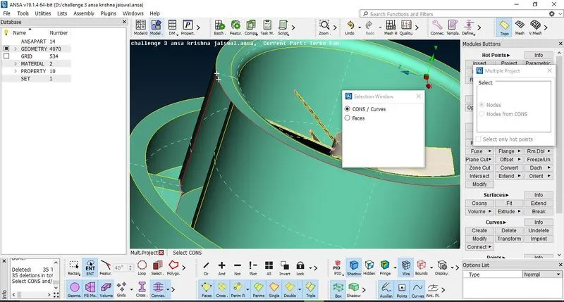
Figure 4: Multiple project of hot points
4. Now create new faces one by one and then fill the remaining surface by using CONS> Fill hole. Thus single CONS is removed. (figure 5 and 6)
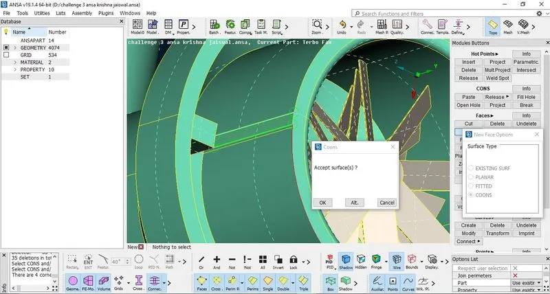
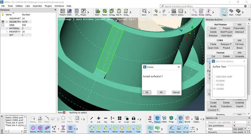
Figure 5: New face creation step by step
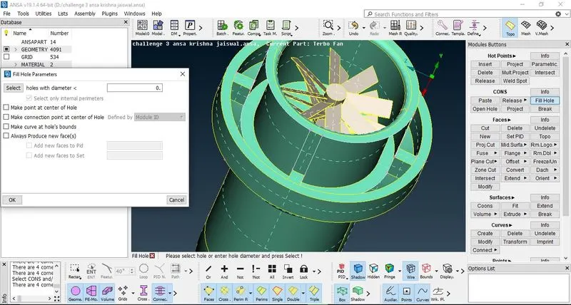
Figure 6: Use of Fill Hole option to fill the required selected entities
5.Now check the remaining single CONS present. Use the Boolean operations and then it can be observed that single CONS present as shown in figure 7. 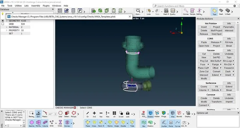 Figure 7: Single CONS Present (which is to be removed)
The surfaces are penetrating within each other thus to remove the single CONS, use Faces > Intersect > select first loop of surface> second loop of surface. Now delete the unnecessary surfaces created.
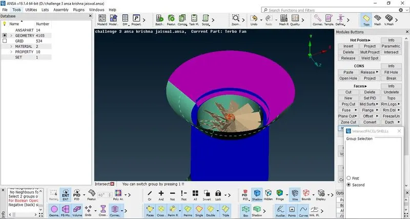
Figure 8: Use of Intersect option (first group selection in purple and second group selection in blue)
8. Delete the overlapped surface. If triple CONS are present use CONS> release> select the CONS. This will release the triple CONS into three Single CONS. Then delete the unnecessary hot points. Now use Faces> Topo> select the CONS. This will make Single CONS into double CONS.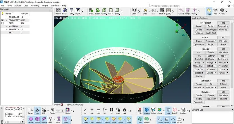
Figure 9: Deleting the overlapped surfaces
9. Now use ALL operation to see complete model. Check for single CONS, create new hot points so that new surface creation will be done in proper steps. Go to Hot Points> Parametric > select the direction as same of length > insert value as 0.5> Press scroll button to confirm. Then create new face one by one.
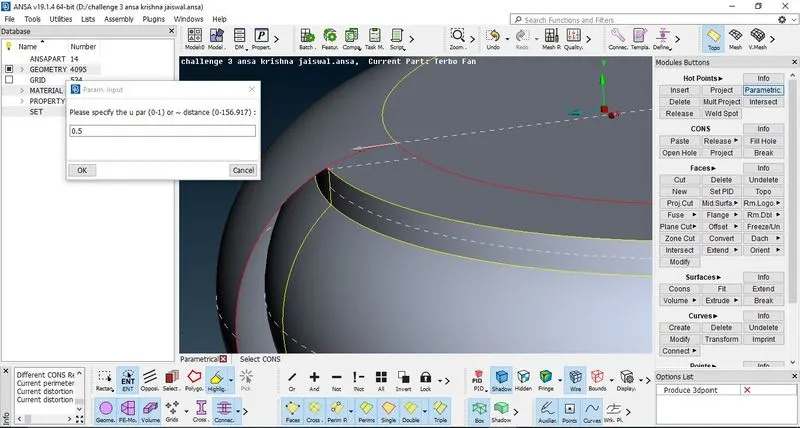
Figure 10: Creating new hot points in aim for creating the surfaces in proper shape using parametric option
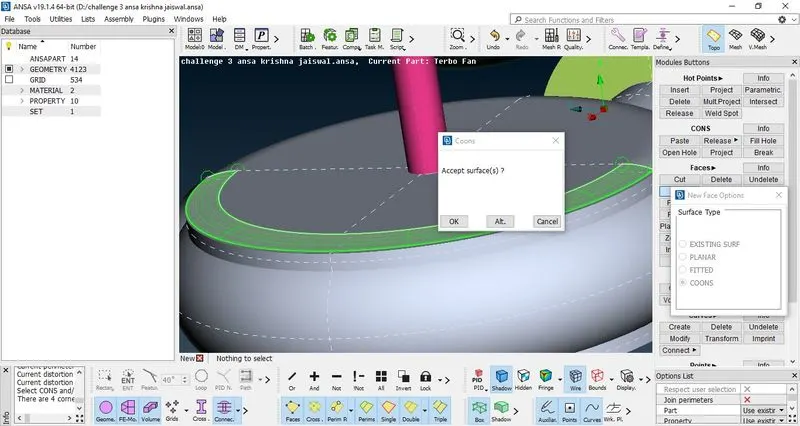
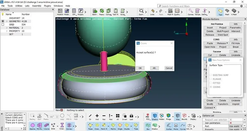
Figure 11: New face creation in steps
10. Thus the new surface will be created and will match with the smooth curved surface. Now again check for any single CONS present in the model by Tools> Checks> Geometry Check> Enable Single CONS. This will show the single CONS and triple CONS present in the model.
11. Now to remove the single CONS present as shown in figure _ , use property manager to hide the unnecessary surfaces and enable only the surface needed. Now to remove this single CONS use the TOPO in the Faces menu to remove the single CONS. This will remove single CONS and will create new triple CONS. Now again perform geometry checks to ensure single CONS is not present. Thus it can be observed that there is only triple CONS present in the model.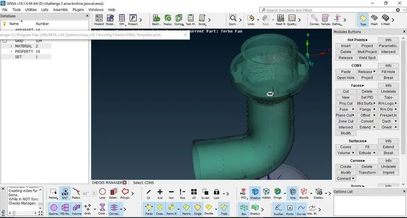
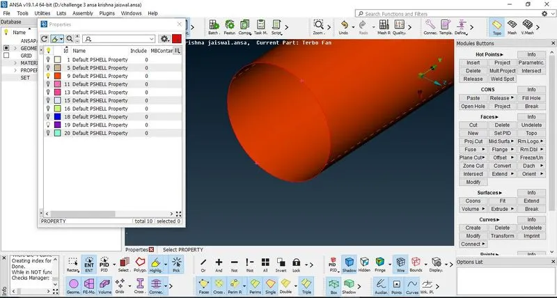
Figure 12: Check for Single CONS
12. Remove the overlapped surfaces and the triple CONS present in the shaft so as to make a single volume (figure 14).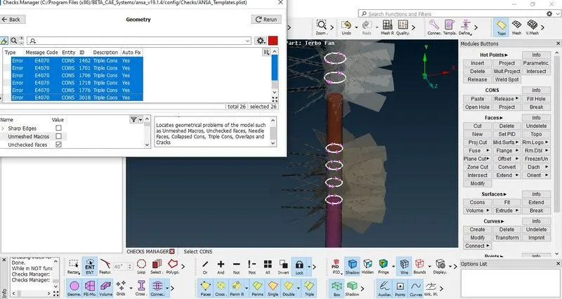
Figure 13: Check for Triple CONS
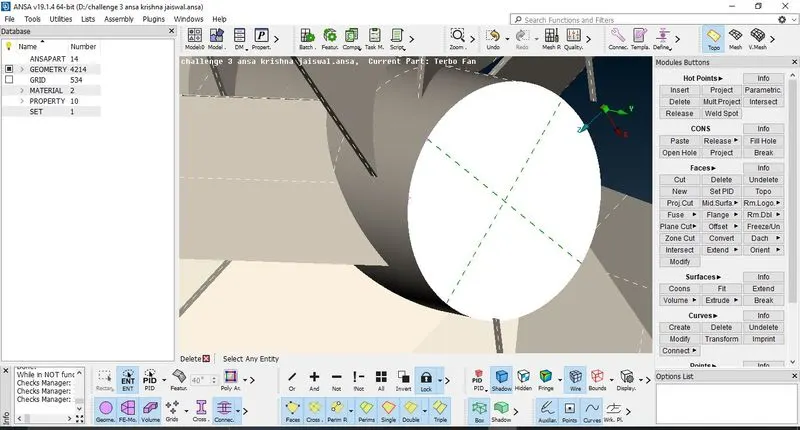
Figure 14: Removal of triple CONS (overlapped surfaces)
Now it can be observed that the cross hatched overlapped in the figure is to be removed. Thus for this removal of overlapped PID’s, separate the overlapped surfaces and then project the CONS on the required face/surface. Then use fine option to improve the CONS resolution.
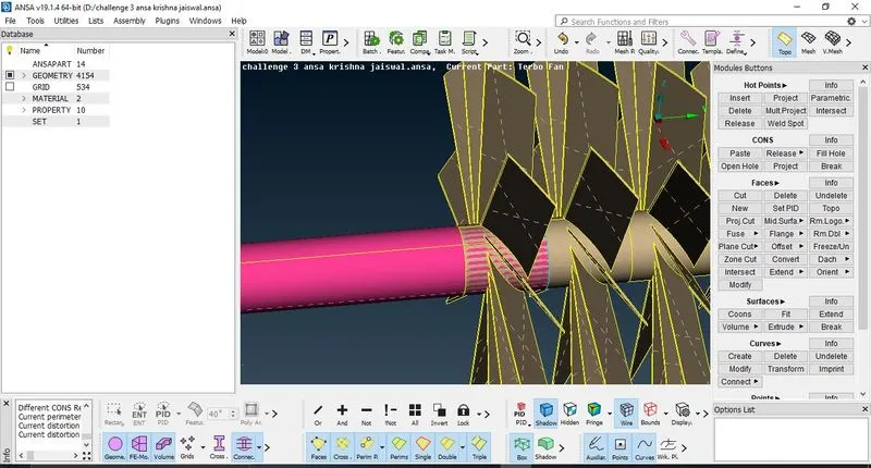
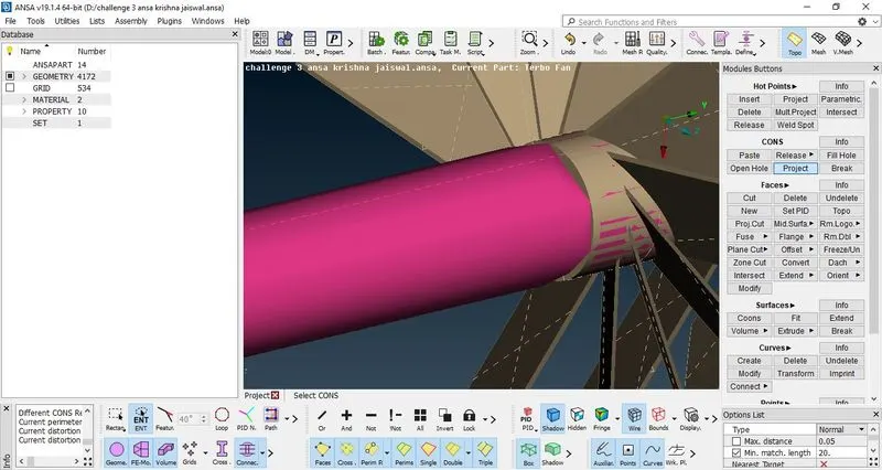
Figure 15: Use of Project option and fining the shape using Fine option
13. After separating two surfaces, use OR boolean operation to view the surface and delete the overlapped surface. Now again release the single CONS and use TOPO to remove single CONS. Now delete the triple CONS and thus required double CONS are achieved.
14.Now delete the overlapped surfaces .further use CUT option to separate the surfaces, TOPO for removing single CONS and then use paste option to pase the single CONS and make it double CONS. Now finally perform geometry checks if single CONS or triple CONS are present.
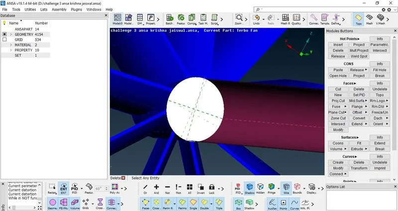
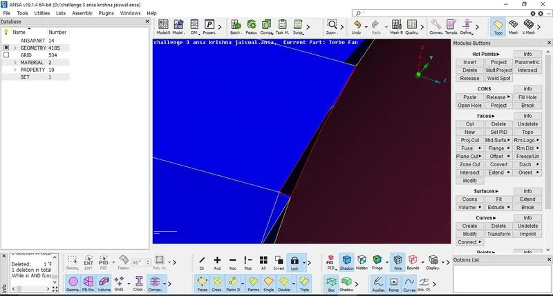
Figure 16: deleting the overlapped surfaces and removing the single CONS of impeller
15. Click on ALL for visibility of all surfaces. Check for geometry checks, moreover to perform volumetric mesh it is required that the surfaces must be closed.
16. Now assign the names of all the PID’s in the property manager one by one. Now delete the unnecessary properties by using COMPRESS option in the tool box > select the PID’s which are additional and unnecessary (not defined)> Ok to Confirm. This will delete the unnecessary PID’s from list. Further close the surfaces one by one and define the names.
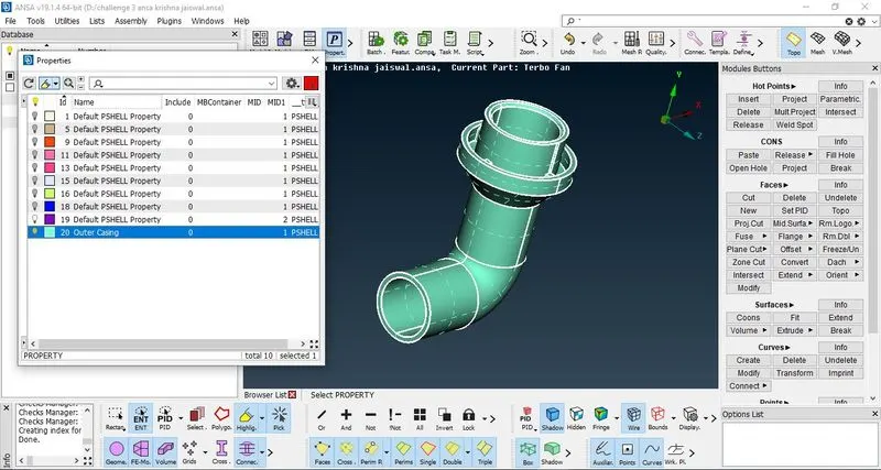
Figure 17: Isolating and closing the PID's so that no errors remains during meshing
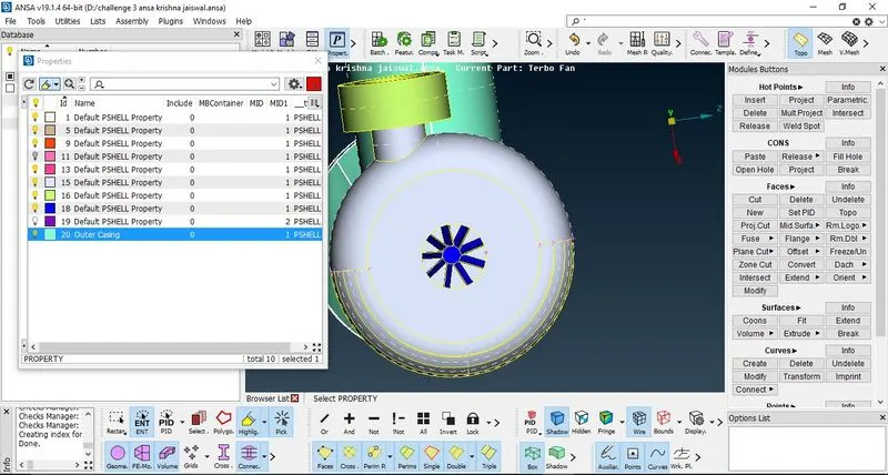
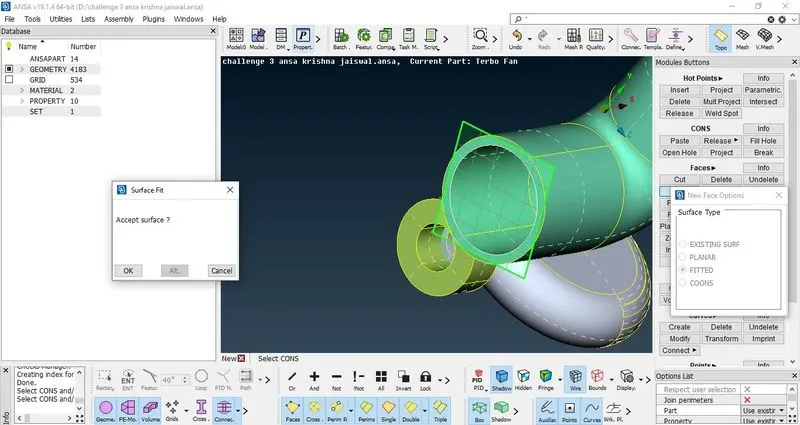
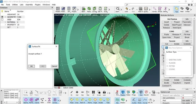
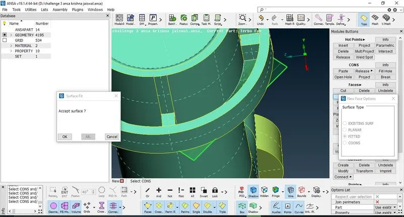
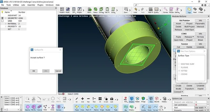
Figure 18: Addition of faces to close the model
17. Now since there is addition of surfaces triple CONS are present in the model which is to be removed one by one. So delete the overlapped surfaces (entities) as shown in figures so that TRIPLE CONS which are not required are removed. Give the names as shown in figure 19.
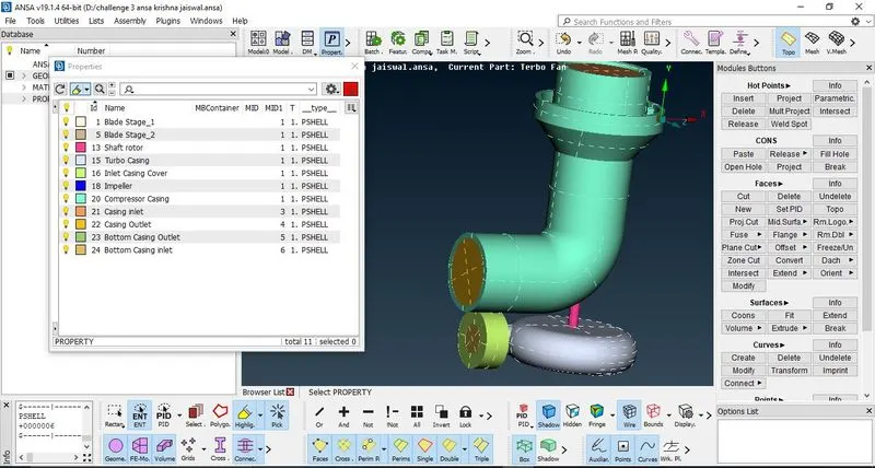
Figure 19: Naming the PID's
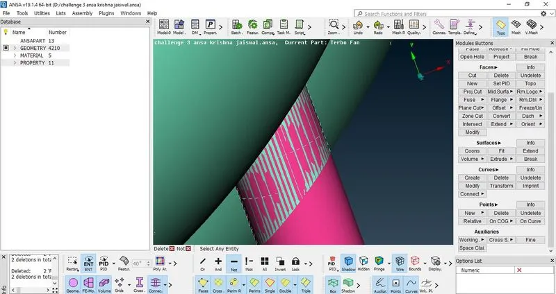
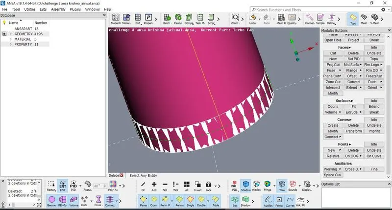
Figure 20: deleting the overlapped surfaces
This ends with Geometry clean-up in the TOPO mode. Now starting with the mesh.
It is required to give the target lengths for different PID’s.
18. Isolate the PID’s one by one. Moreover, it is possible to give different quality criteria to different PID’s. Go to Properties> select the required PID’s> right click> click on Show Only. This will isolate the required PID.
19. Now the procedure to perform mesh is explained in following substeps: -
A) Compressor Casing
Target length = 5mm
i) Go to Quality Criteria> Minimum length = 3 ; Maximum Length = 7> Ok to Confirm
ii) Go to Mesh Parameters> Target length = 5, min. target length = 3, max. target length = 7, element type = tria> Ok to confirm.
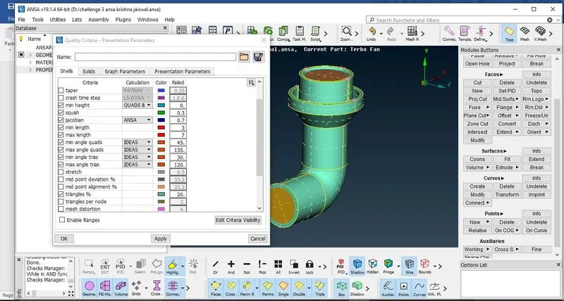
Figure 21: Giving the mesh parameters and quality criteria
iii) Change module from TOPO to Mesh. Go to Perimeters> Length> select the complete model> give length value =5, Then Macros > Value=5.
iv) For creating mesh, Mesh generation> Spot meshing> select the complete model> Scroll button to confirm
This will create surface mesh for compressor casing as shown in figure.
B) Turbo Casing and inlet casing cover
Target length = 5mm
i) Since the mesh parameters and quality criteria are already set up so now go to Perimeters> Length> select the complete model> give length value =5, Then Macros > Value=5. Then create mesh by Mesh Generation> Spot Mesh> Visible. This will generate surface mesh of 5mm target length. (figure)
Similarly, first in focus toolbox click on ALL and this will enable the visibility of complete turbocharger, now follow the same steps to mesh the outlet and inlet bottom casing covers. (Figure)
C) Impeller
Target Length= 2mm
i) Change the minimum target length in quality criteria and mesh parameters = 1 and maximum target length = 3.
ii) In mesh parameters, change the target length = 2mm.
iii) Go to Perimeters> Select the impeller section only> target length=2, Macros> select the impeller by switching from ENT selection to PID selection> value= 2. Now generate the mesh by Mesh generation> Spot mesh> Select> Select the impeller using PID selection> Scroll button to confirm. This will create the surface mesh on impeller.
D) Blade Stage 1 and 2
Give the target length = 1mm and change the minimum and maximum values to 0.5 and 2mm. Then repeat the same procedure to perform surface mesh.
E) Shaft rotor
Give the target length = 1mm and then perform surface mesh by repeating the procedure and selecting shaft rotor by PID selection.
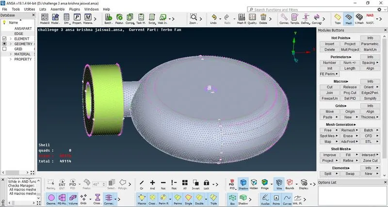
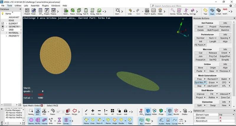
Figure 22: Meshing the PID's one by one as per target length defined
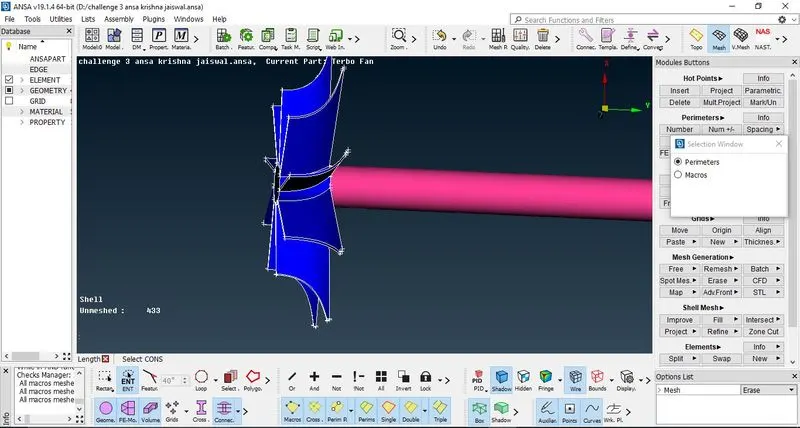
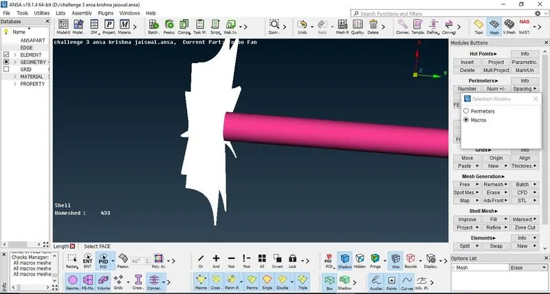
Figure 23: Meshing the impeller
20.Now mesh the unmeshed macros(surfaces) so that no surface remains unmeshed.
21.Then isolate the surfaces where the mesh length varies from given mesh length by using CUT option in the macros and making a boundary to isolate the surface where the mesh length varies from given mesh length (target length).
This completes the surface mesh.
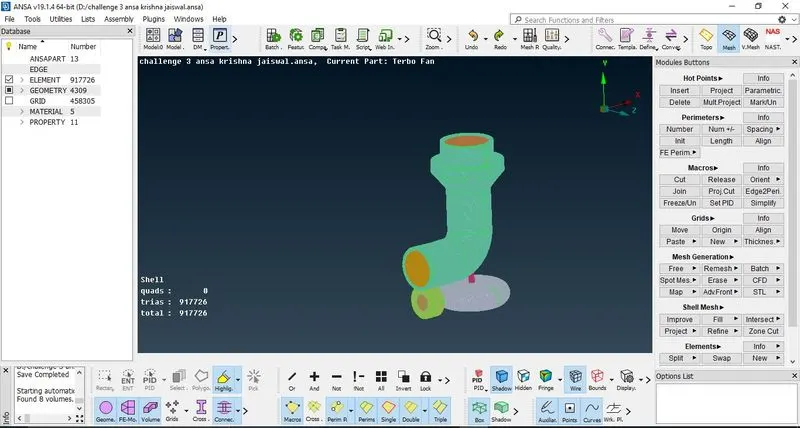
Figure 24: Surface mesh on turbocharger model
Tria mesh with mesh count = 917726
22. Now to perform volumetric mesh, switch the module from Mesh to Volumetric Mesh.
23. In volumes, define> Auto detect > Select whole database > Ok to confirm. Thus ANSA will auto-detect the surfaces which are volumetrically unmeshed. Thus now keep the volumes which are required and delete the unnecessary volumes.
24. Volumetric mesh must be done where the actual fluid will flow, that is in the space or voids where the fluid will be flowing thus it is necessary to delete the volumes which are not required (wherein the fluid won’t be flowing).
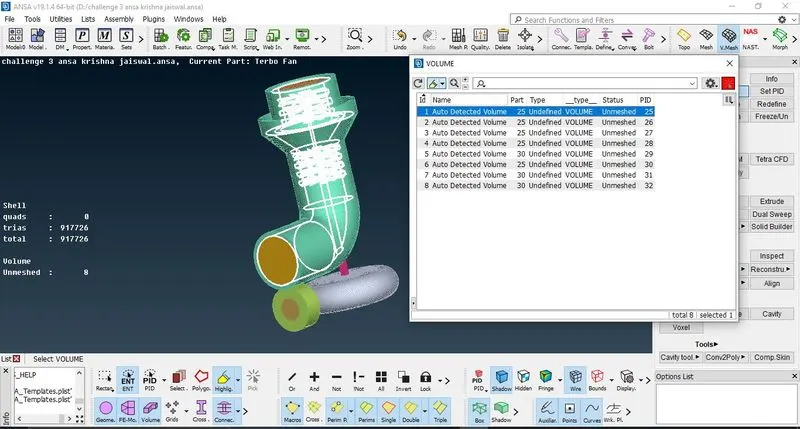
Figure 25: Defining the volumes and deleting the unnecessary volumes
25. Now as ANSA detected 8 volumes, delete the volumes which are unnecessary for doing volumetric mesh. Click on show only to see the remaining volumes which are required. Then to perform mesh, click on the desired volume > Remesh >Tetra CFD (as application is CFD application)> Click Ok. Thus meshing will be done on that volume. Repeat this same steps for performing volumetric mesh on desired volumes of turbocharger.
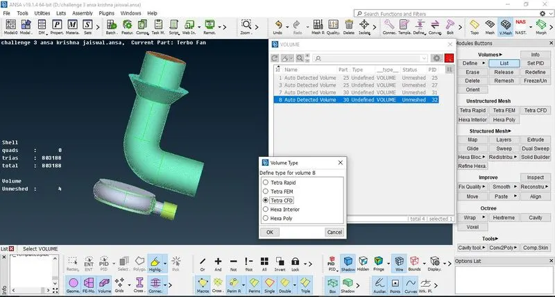
Figure 26: Performing Volumetric mesh
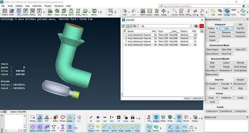
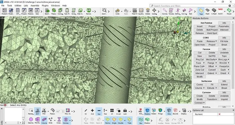
Figure 27: Volumetric mesh done
This completes the volumetric mesh of the model. Now to check the volumetric mesh go to TOPO module, turn ON the volumes in toolbox bottom. Then use NOT operation to see the volumetric tetra elements. Thus this completes the procedure.
Conclusion: -
Thus the CFD volumetric and surface meshing was done on turbocharger model with different target elements.
Learning Outcomes:
Proper geometry cleanup with closing the PID’s for meshing, proper face creation at irregular surfaces, use of multiple options to correct the Single CONS, surface meshing with different mesh lengths, Volume definition, overview of volumetric meshing with necessary volumes needed, and the reason of volumetric meshing over desired volumes as fluid flows over the volumes. More proper meshing thus giving good results.
Link to download the model:
https://drive.google.com/file/d/1voExvALhZKEd7HqnFZoJgjPA4L9_yhDp/view?usp=share_link