Project 1 : CFD Meshing for Tesla Cyber Truck
TITLE: - CFD Meshing of Tesla Cyber Truck
Aim: - To perform CFD meshing of Tesla Cyber Truck with appropiate mesh length with no offset elements.
Problem Statement: -
For the given model, check and solve all geometrical errors and Assign appropriate PIDs. Perform meshing with the suitable Target length and element Quality criteria. No offset elements should be present.Target lengths for the different parts of a model can be decided by your own. Finer mesh will give good results and will compromise with the longer processing time.
Procedure: - The procedure is explained in steps starting with geometric cleanup of model, then meshing the model and further creating the wind tunnel.
Geometric Cleanup
1. Import the given model into the ANSA software.
Model will be imported and can be displayed, then to perform initial geometric cleanup and to remove the single CONS, Faces > Topo> Select all faces > Press scroll to confirm. This will remove the possible single CONS.
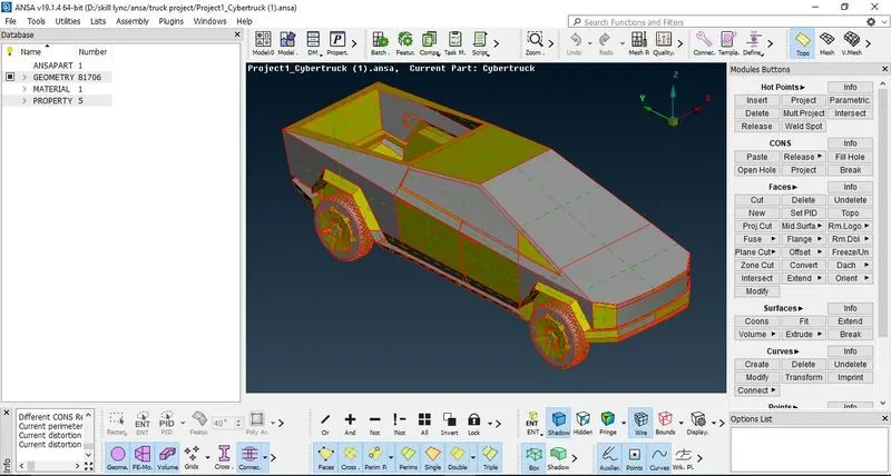
Figure 1: - Truck model imported into the ANSA software
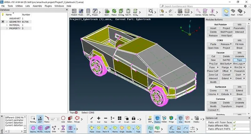
Figure 2:- Using TOPO to remove the possible Single CONS
2. Fill the back empty gap by creating new face. (Faces>New> Coons > Edge selection>Ok to Confirm)
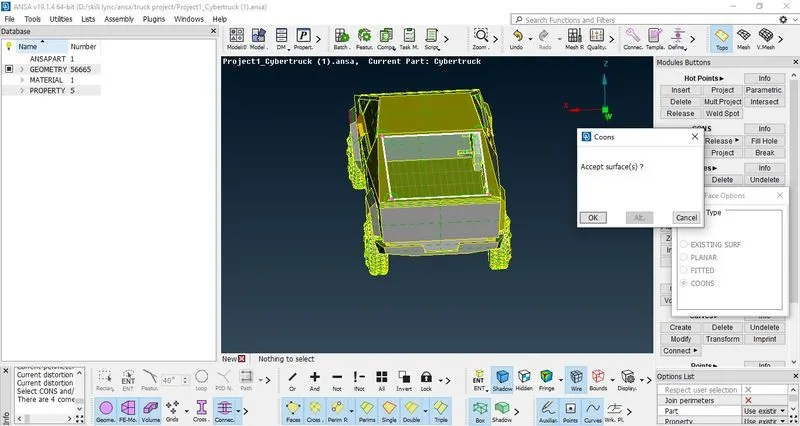
Figure 3:- Filling the empty space by creating new face
Make a plane cut at centre as we can work on geometric cleanup over half model and then can be mirrored.
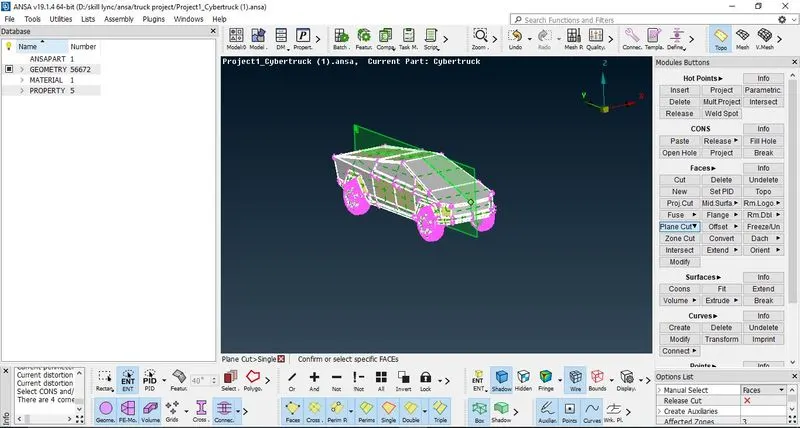
Figure 4: - Making a plane cut from centre so as to make the truck model divided into Half
3. Now since the model as some irregular shapes, to turn it to proper shape, switch the mode from TOPO to MESH, Perimeters> Length> perimeters>Select complete model and press scroll to confirm> Length = 1mm> Ok to Confirm. This will make the model proper and refined shaped.
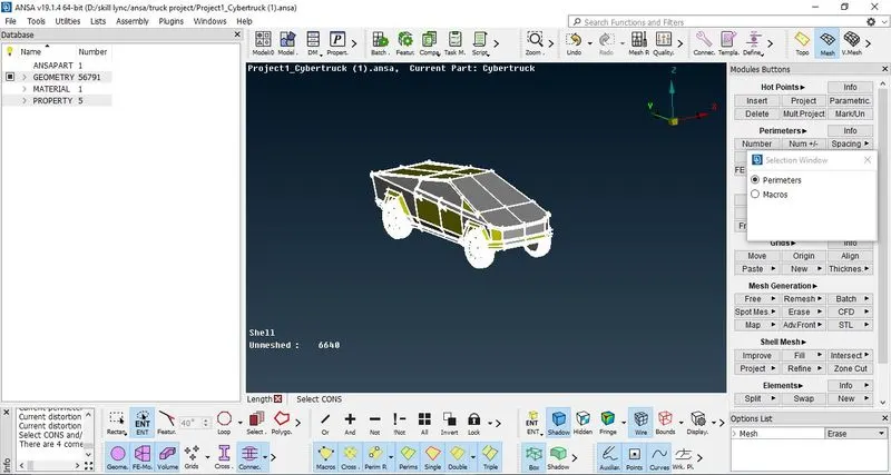
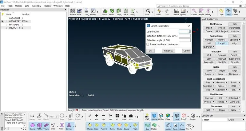
Figure 5: - Refining the model so that irregularities in the model are removed
4. Delete half the model so that all the operations can be carried out only on remaining half model and then can be made again using copying the entities. This will reduce the time to work on the model and also will give better results.
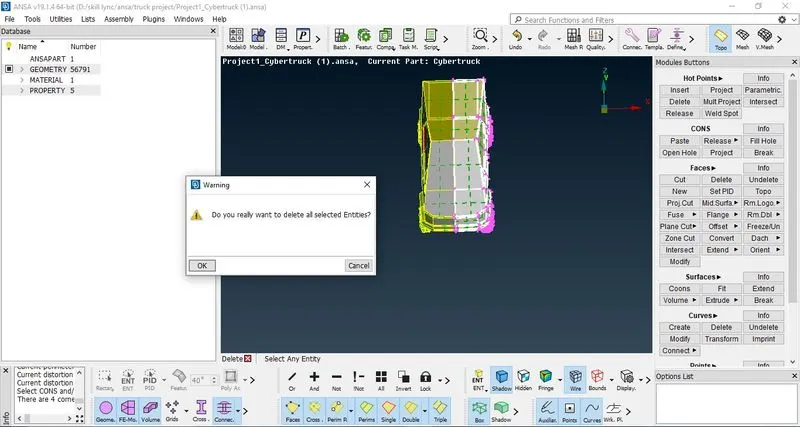
Figure 6: - Deleting half model
5. Perform geometry check by Checks> Geometry> Geometry check CFD in Templates. This will show all the errors of collapsed CONS, Needle CONS, Single and Triple CONS, Cracks and Penetrations, Convex and Concave CONS.
6. After performing geometry checks, start performing geometric cleanup by removing single CONS.
Make a cut so that unnecessary surfaces are detached from the existing surfaces and can be deleted one by one which are not required.
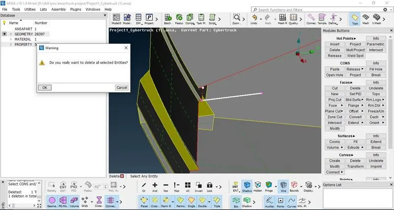
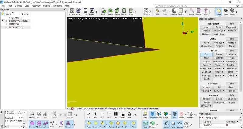
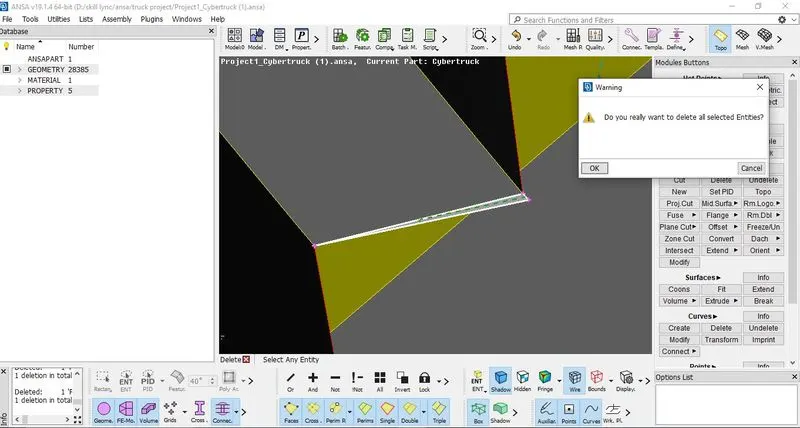
Figure 7: - Creating cuts and deleting the unnecessary surfaces from the model
7. Now fill the gaps that are present by creating new faces. After completing the geometry cleanup, again perform geometry check if intersecting surfaces are present or not.
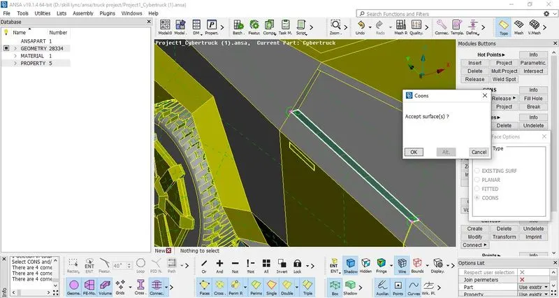
Figure 8: - Closing the empty faces by creting new face
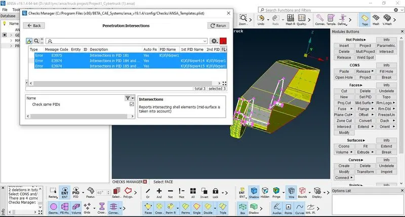
Figure 9: - Performing Geometry Check: Penetration:Intersection
8. Since intersecting surfaces are present, now it is required to delete the overlapping suurfaces by making cuts and deleting the intersecting surfaces. Starting with overlapping surface one above another switch the viewmode from ENT to PID for ease in detecting the overlapped surfaces. It can be seen near the wheels from the inside, delete the overlapping surface by Delete> clicking on the cross hatch of the surface which is to be deleted> Ok to Confirm.
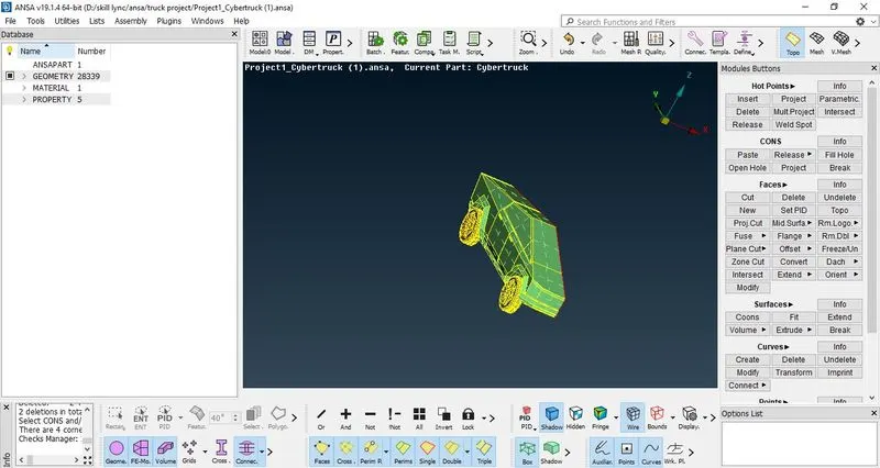
Figure 10: - Switching the mode from ENT to PID
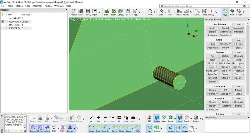
Figure 11: - Detecting the overlapping surface
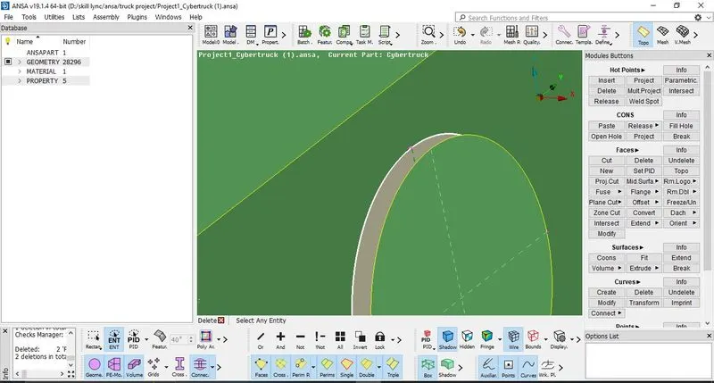
Figure 12: - Deleting overlapped surface
After deleting the overlapped surface, the empty surfaces is to be filled so that single CONS at that location is removed. Use the Fill hole option by CONS>Fill hole > select the edge> Ok to Confirm.
Similar procedure for another wheel surface inetrsecting from inside.
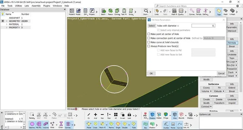
Figure 13: - Fill Hole option to fill the hole and create the surface
9. Now again perform Geometry Check, so that it can be cross checked that the geometry cleanup is done properly or not. It can be observed only one error of intersecting surface is remained. ( The single CONS that are shown over the half region edge is depicting that there is no surface present. It is not to be considered as after completing the meshing the half model can be made copied symmetrical and all the Single CONS at that location will be removed).
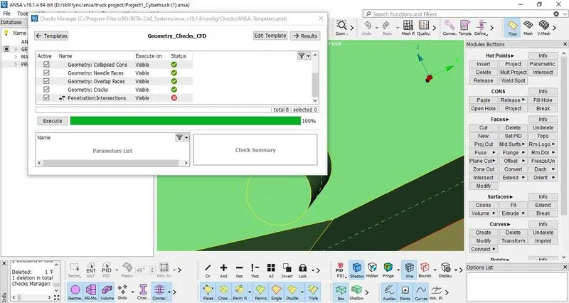
Figure 14: - Performing Geometry Check CFD
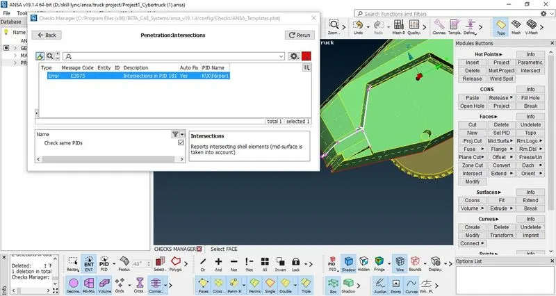
Figure 15: - Error shows that intersecting surfaces are still remaining which is to be corrected
10. Switch the mode from PID to ENT. Then Use the I- Not Option > Select the surfaces which are intersecting > Press scroll to hide remaining surfaces. This is done iin order to perform geometry cleanup properly. Then lock the view.
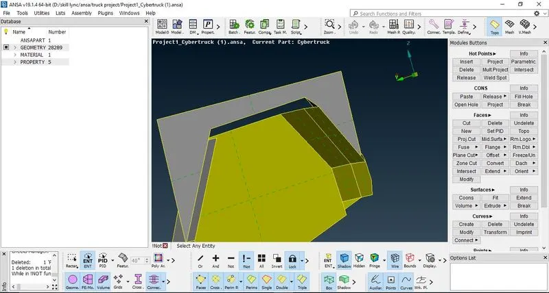
Figure 16:- Using the I-Not option to isolate the intersecting surfaces
11. Now start making cut, use not option to hide a particular face and then delete the sharp edges as shown in figures.
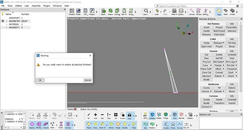
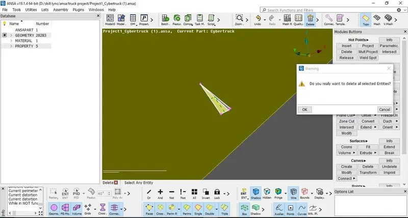
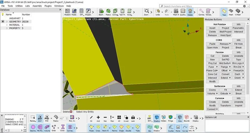
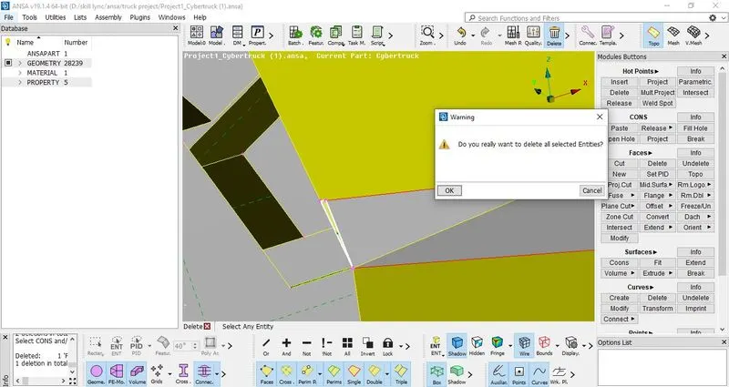
Figure 17: - Making cut and deleting the intersecting sharp surfaces
After deleting the surfaces, the surfaces must be closed so that no single CONS remains. This can be done by creating new edges by Curves> Create>Selecting two hot points> Press scroll to confirm. Then make surfaces one by one using the same procedure of creating face. Then further after creation of faces, delete the created curve. Use TOPO after deleting so that the single CONS present converts to double CONS
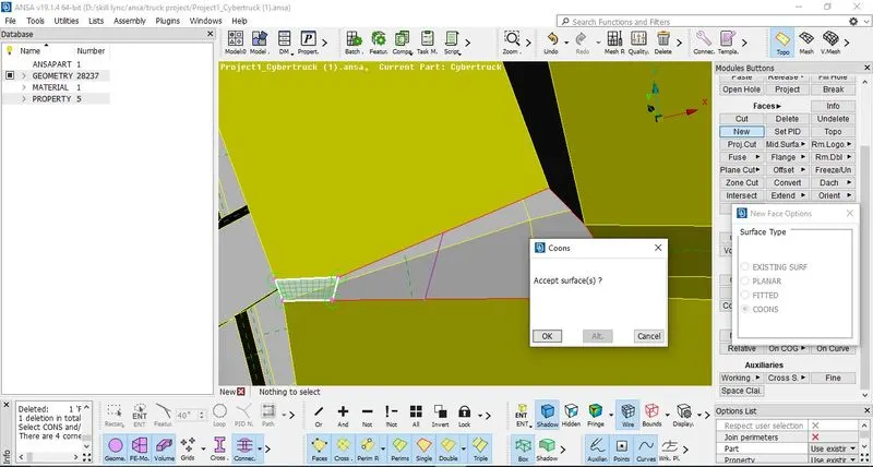
Figure 18: - Using create curve option so that new face can be created properly and then further deleting the created curves after face creation
12. As there is spacing present between doors it must be filled so that during meshing there must be no problem. Thus delete the inner surface which is not required and create new surface so that there is no space present.
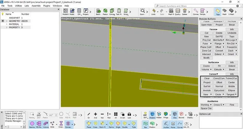
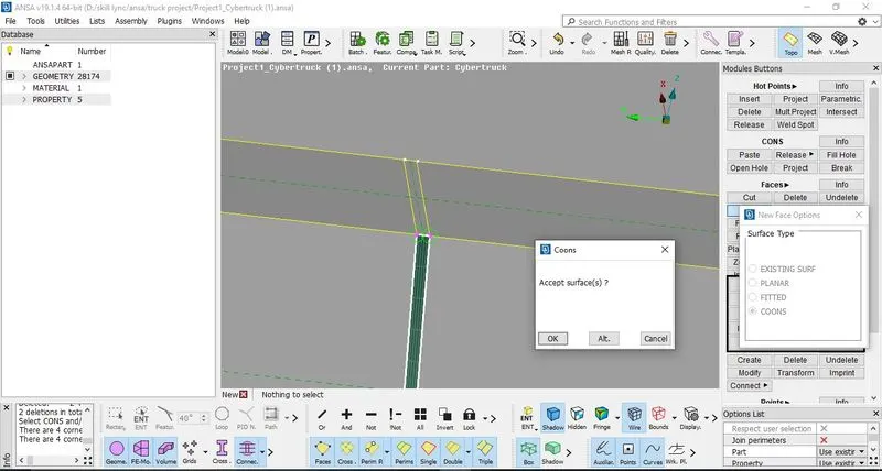
Figure 19: - Filling the space between doors by deleting inner unnecessary surface and creating new surface
13. It can further be seen that unnecessary CONS are present at the intersection of window and doors, in order to remove initialy use the Cons2Curve option to make an imprint of the CONS before deleting and recreating the faces. This can be done by Curves> Cons2Curves> select the CONS that are to be deleted further. Delete the window and adjacent surfaces so that the unnecessary CONS gets removed, further again create the new faces using the curves. Then create the window surface and delete the curves that were created by Cons2Curves option.
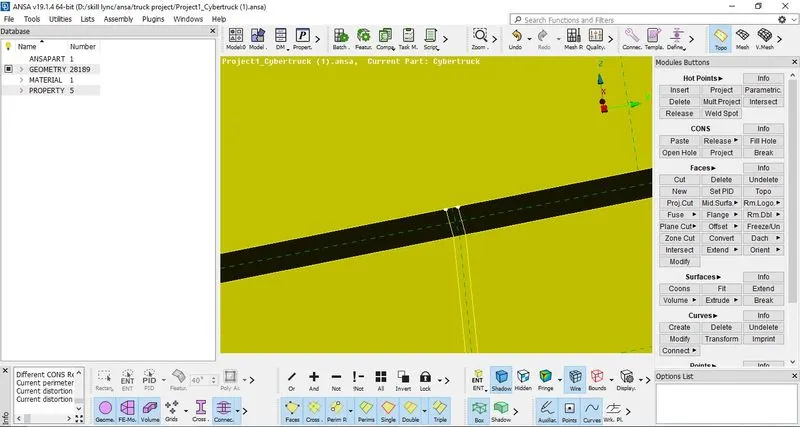
Figure 20: - Unnecessary CONS present which is to be removed
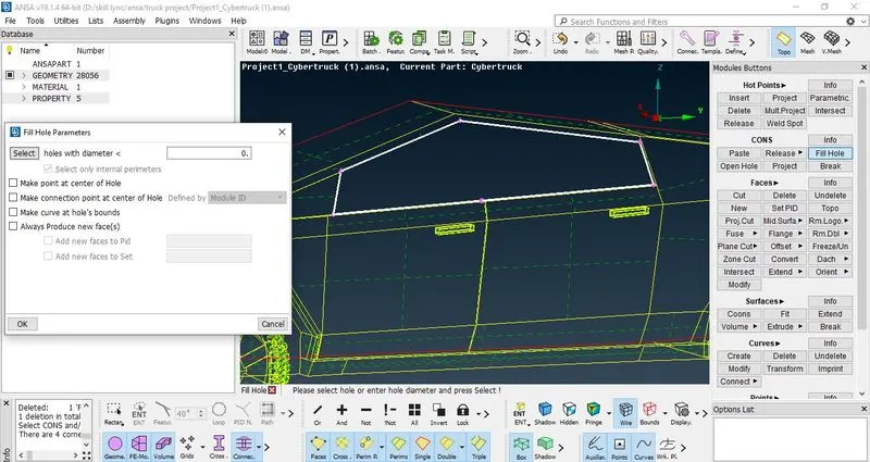
Figure 21: - Creating the window surface
14. Now perform the Geometry Check. It can be seen that no error is present thus can be proceed further to meshing.
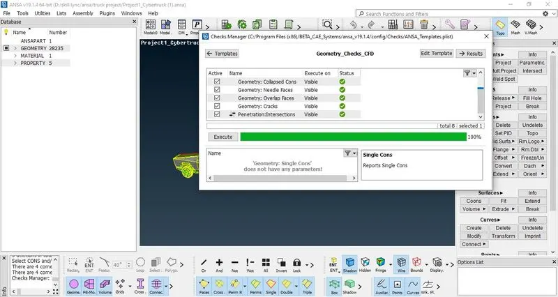
Figure 22: - Performing geometry check (no error present)
This completes the geometry cleanup of Truck model. Now starting the meshing of CyberTruck model follow the below procedure.
Meshing
15. Initially before starting any CFD mesh it is required to assign the PID's so that meshing can be done with proper target length and with quality criteria. Go to properties manager (PID manager tab) and create new PID's naming as
a) Lights b) Tyres c) Body d) Windows
After creating the PID's assign the PID's over the same as defined by names. After assigning the PID's to remove the unnecessary PID's go to toolbar, use Compress option and then confirm all selections. This will remove the other unassigned PID's from PID manager (Properties manager). Again open the PID manager to check that the PID's were defined and assigned properly or not.
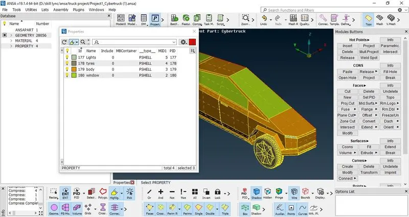
Figure 23: - Assigning the defined PID's and compressing all other unassigned PID's
16. Following quality criteria and target lengths were defined for the PID's with shape of mesh element to be TRIA.
Skewness = 0.5
Min length = 0.5
Max Length = 6
TABLE 1: - DETAILS OF MESH TARGET LENGTH AND ELEMENT TYPE TO BE ASSIGNED TO PID'S
| Sr.No | PID name | Target Length | Element type | Min target length | Max Target Length |
| 1 | Tyres | 2 | Tria | 1.5 | 2.5 |
| 2 | Windows | 2 | Tria | 1.5 | 2.5 |
| 3 | Lights | 4 | Tria | 3.5 | 4.5 |
| 4 | Body | 3 | Tria | 2.5 | 3.5 |
Go to quality criteria and tick only the required quality criteria, edit the criteria visibility to only skewness, min length and max length. Then assign the values of quality criterias as mentioned above. Change the colours and click ok to confirm.
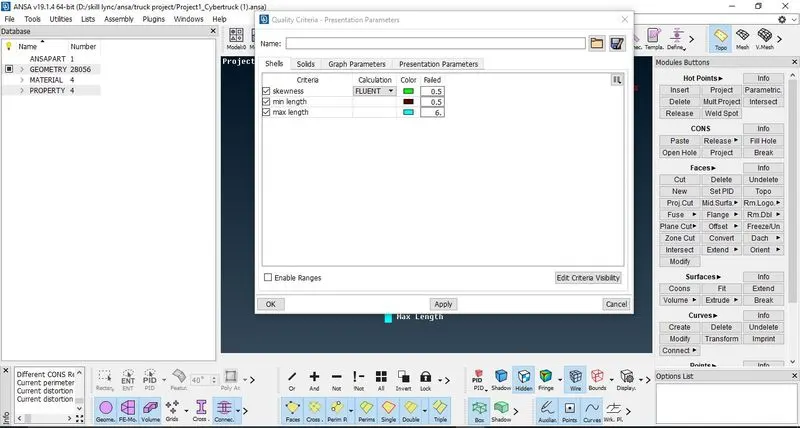
Figure 24: - Defining the quality criteria
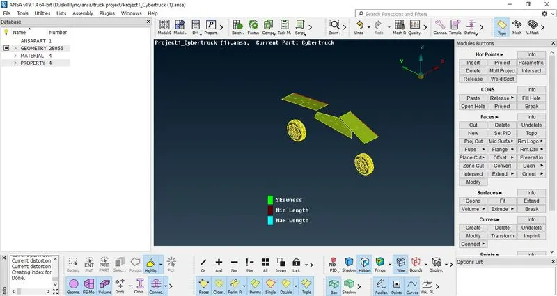
Figure 25: - Turn on the hidden mode to observe the quality criteria
17. Starting with meshing of Tyres and windows as target length is same i.e equal to 2, define the target length in mesh parameters with minimum target length = 1.5 and maximum target length = 2.5, Ok to confirm. Then go to Spacing> AutoCFD> define the same range of target length> Ok to Confirm. Then go to mesh generation > CFD> Press scroll to Confirm. This will mesh the windows and tyres with required target length. Now if off elements are present, right click on Off elements> Improve> process the steps given and then observe the improvement. Repeat this procedure to remove the Offset elements.
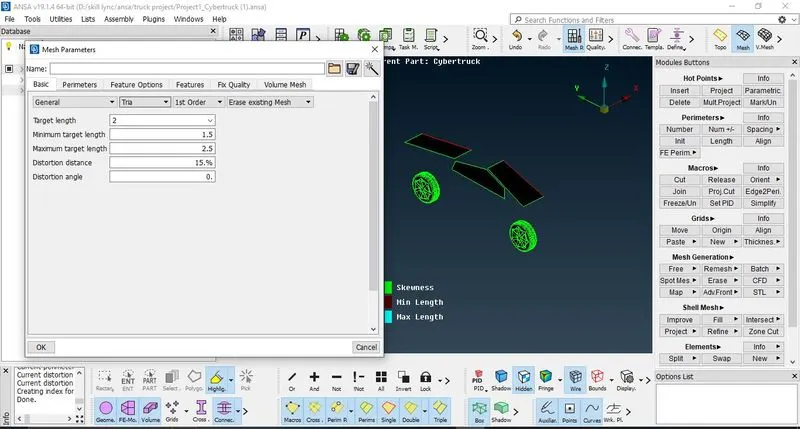
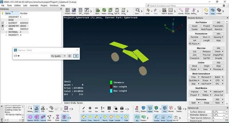
Figure 26: - Defining mesh parameters, meshing the windows and tyres and improving the quality to remove the offset elements
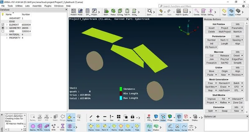
Figure 27: - Meshing the windows and tyres with zero offset elements
This depicts that the meshing done is correct and has passed the quality criteria.
Freeze the mesh so that during meshing of other PID's it wont distort the target length of this PID's. To freeze, go to Macros> Freeze > select the PID> done.
Now repeat the same procedure for other PID's.
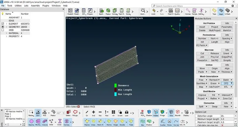
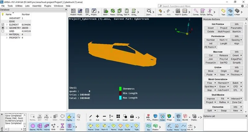
Figure 28: - Meshing the light and body with defining new target length (refer table 1) and improving the mesh so that no offset elements present
Thus, this completes the meshing of half model of Cybertruck. To complete the model, Transform> Copy> Select 3 point mirror axis, selecting 3 points one at top, front and rear of truck. Ok to confirm. This will create the remaining half model, if single CONS present, use TOPO or paste the 2 single CONS so that it will form double CONS.
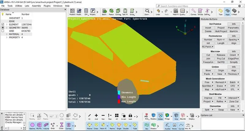
Figure 29: - Creating remaining model with copy and symmetry option
Here ends the surface meshing with zero offsets of cybertruck model.
Now for developing the CFD simulations, Wind tunnel is to be created. Wind tunnel is used wherein there is study of flow over the car body or an airplane, it simulates the air flow and the effect of incoming air can be observerd over the car or airplane model. Air is blown at known velocity so that how the air flows around the airplane part wing or model or car model and effect of increase in air velocity over the model.
Creation of wind tunnel
a) To create a wind tunnel,
- From the front face of the truck, 4*Length of truck
- From the taillights, the minimum distance must be 6*Length of truck
- From the top face of truck, the minimum distance must be 3*Length of truck
- From the side faces of truck, the minimum distance must be Length of truck
- From the bottom face of truck, the bottom face of wind tunnel and tyres of truck must not be intersecting.
b) Measure the length of truck.
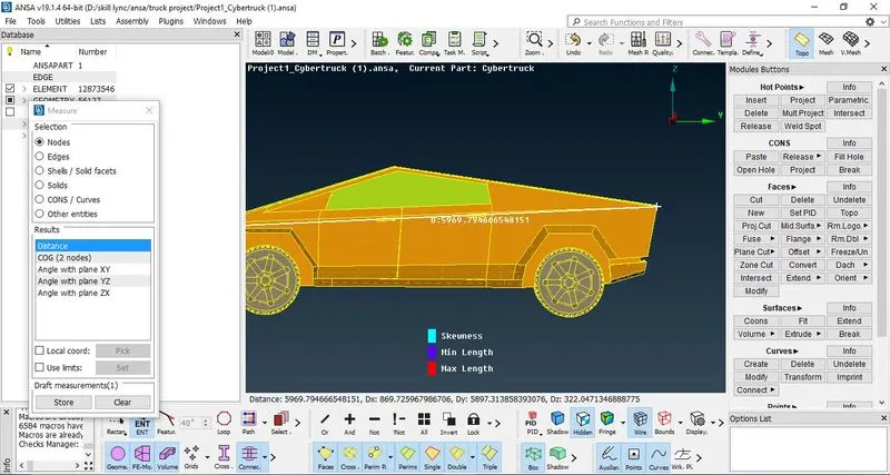
Figure 30: - Measuring the length of cybertruck
Length of truck = 5969.79, so we take the value to be more than 5969.79.
Here we take the length to be 5975 so that wind tunnel is created in proper way and is better for CFD simulation purpose.
Distance from the front face = 4*5975 = 23900
Distance from the rear face = 6*5975= 35850
Distance from the side faces = 5975
Distance from bottom = 2000
Distance from top face= 3*5975 = 17925
Make new points from that distances by creating reference point and then creating all points at distances given above.
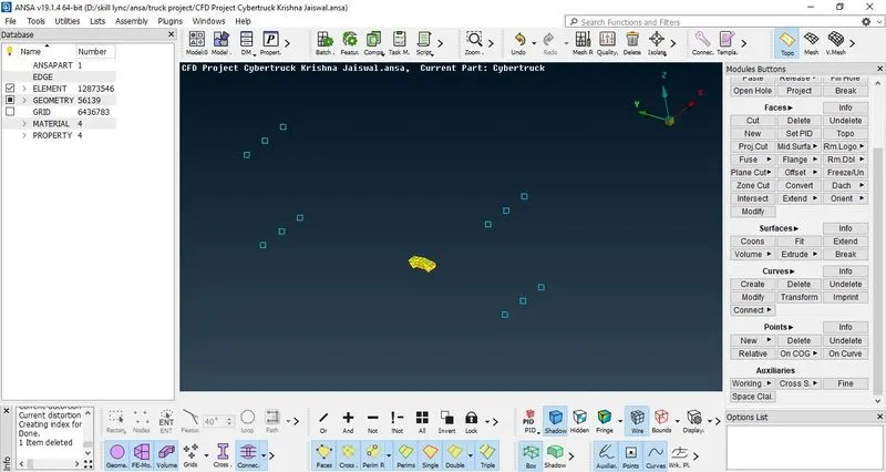
Figure 31: - Creation of points to create wind tunnel
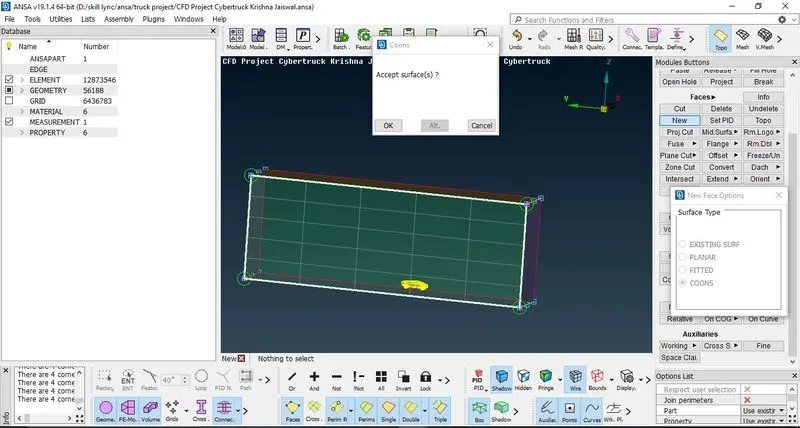
Figure 32: - Creating wind tunnel
Then Curves> create > join the points one by one> press scroll to confirm. Then create new faces so as to create wind tunnel of cuboidal shape.
Then delete the points and curves created, use TOPO to form all single CONS to double CONS. Thus wind tunnel is created
c) After creating wind tunnel, define new PID's as
- top face of wind tunnel
- bottom face of wind tunnel
- side faces of wind tunnel
Assign the PID's accordingly to the wind tunnel.
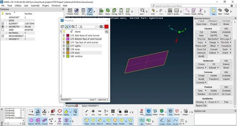
Figure 33: - Assigning the PID's of wind tunnel and hiding the surfaces in order to mesh bottom face step by step
d) Hide all PID's and make bottom face of wind tunnel visible so that meshing can be done properly step by step. Again switch the mode from TOPO to mesh. Then give the target length for bottom face of wind tunnel = 30mm and tria as element type
Follow the same procedure of meshing as described earlier.
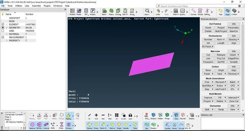
Figure 34: - Meshing the bottom face of wind tunnel
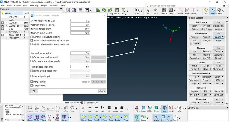
Figure 35:- Meshing the top face of wind tunnel
Then work on top face of wind tunnel by hiding all other PID's. Give the target length for Top face = 110, mesh the top face of wind tunnel and tria as element type.
After meshing the top face, now mesh the side face, for the side faces create mesh with growth rate. This can be done as follows:
- Go to properties manager (PID manager) and enable the visibility of all sides of wind tunnel. Then go to perimeters> Spacing > Manual> Biasing= Geometric; Factor = 1.2, dmin = 30; dlimit = 110, direction from bottom to top> Ok to confirm.
- Mesh generation > CFD > Visible. This will create growing mesh on side faces of wind tunnel with direction from bottom to top face.
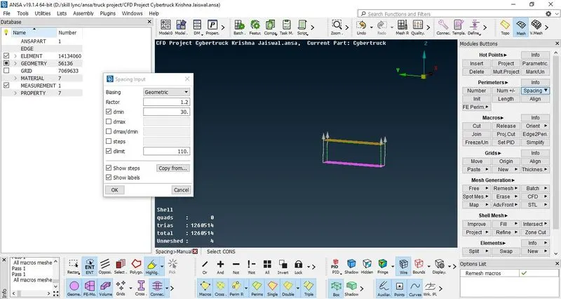
Figure 36: - Meshing the side faces
Thus this completes the meshing of wind tunnel also.
Conclusion: - Thus the CFD meshing of cybertruck with creation and meshing of wind tunnel is done with no offset elements.
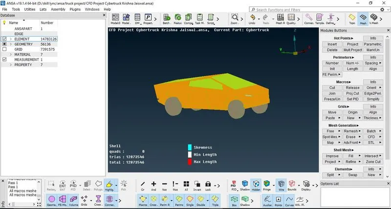
Figure 37: - CFD meshing done of Cybertruck with zero offset element present
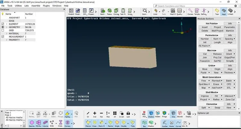
Figure 38: - CFD meshing done on wind tunnel with growing mesh at side faces.
Link to download the project: -
https://drive.google.com/file/d/1-4GB8jLpX0BR8pzhLVQuHKeNlbq8AU5g/view?usp=share_link