Week 4 Challenge : CFD Meshing for BMW car
aim: For the given model, check and solve all geometrical errors on half portion and Assign appropriate PIDs. Perform meshing with the given Target length and element Quality criteria.
- Target lengths for the different parts of a model are as follow:
- Body - 3 mm
- Lights - 4 mm
- Grills - 1 mm
- Rims and Tyres - 2 mm
- Optical Rear view mirror - 2 mm
- Window - 2 mm
- Silencer - 3 mm
- Logo - 1 mm
procedure
1.for the below model we have to done surface cleaning and then surface meshing
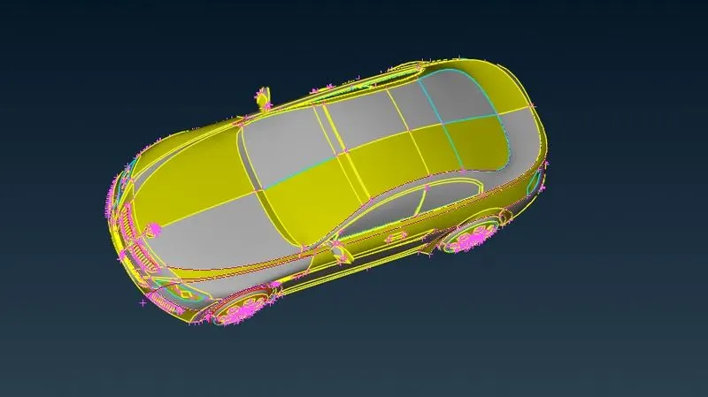
2.we can see that there are some glitches on surface and resolution of model is not proper sso we have to define proper resolution for the model
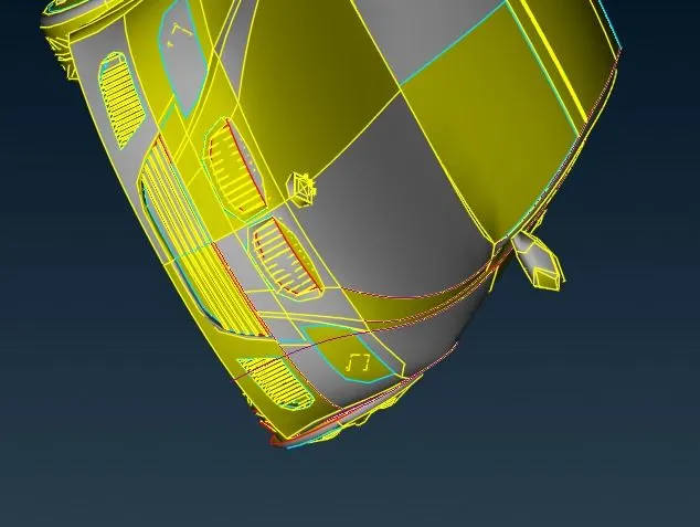
3.we can define the resolution by defining perimeter =1mm
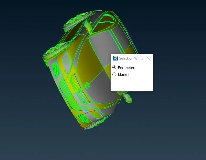
4. after defining 1mm length we can see the surface is now clear
5.now we have to check the resolution
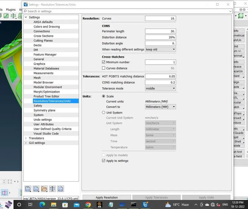
7.after checking the resolution we have to geomatric check and after geomatric check we see that there are 33 errors are showing so we have to clear all geomatrical error
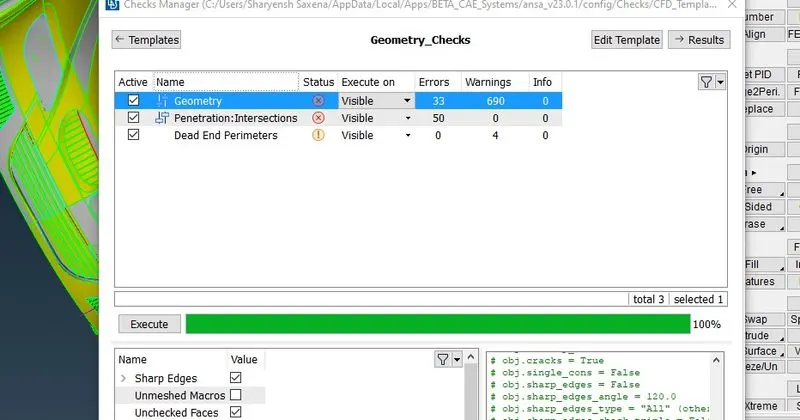
8. we clear geomatrical error by taking seprate surface taking half part of bmw we will clear geomatricall error in half part then mirror so first we will delete half the half part by universal delete
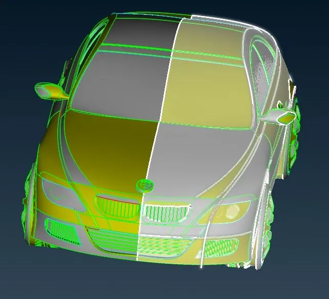
9. taking the grill part from rest half bmw and clear all error
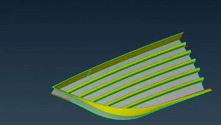
10.from below fig we can see that the geomatry are not proper align and there are triple cons too
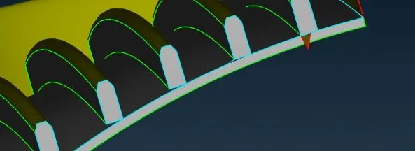
11.deleting the extra surface by universal delete
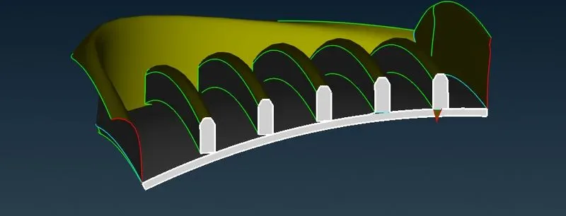
12.from below surface we can see that triple cons are gone by deleting extra surface and delete the left surface which is not required
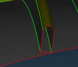
13.after deleting extra surfcae we can see that the surface are not align so we have to align the surface by project cons option( first we will select project con and then surface on which con will project then ok) when the con is projected we can see that the con is not refine for refining we will select the con and give quqlity criteria 1 for peremeter
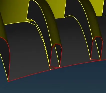
14. we can see that the con formed is not connected from the end surface so first we have to extand con till the surface by using cut option select the con and extand in the direction we disired
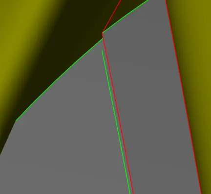
15.after con formed create surface as shown in figure by selecting new con
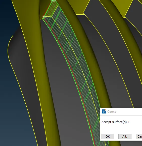
16. after creating new surface we can see that the surface are not joined properly so we join the surface by projecting cons (select the con shich have to project and then select the rear surface
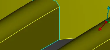
17. after creating surface from below fig we can see that triple cons are fomed and overlaping of surfaces
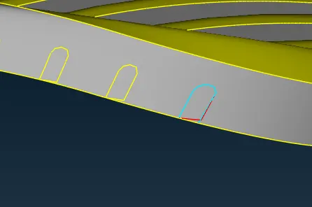
18. so we have to delete the extra surface and intersecting surface after deleting the surface rest part will be show as
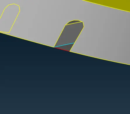
19.from below fig we can see that there are another triple con are formed and we have to delete also by unoiversal delete and we have to do same procedure for all the grills and in the last we have to do geomatric check for grill
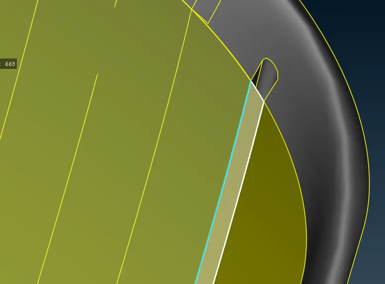
20.after clearing all geomatrical error take another grill for clearing geomatrical error and intersection error and we can see from below fig triple cons are present on the grill
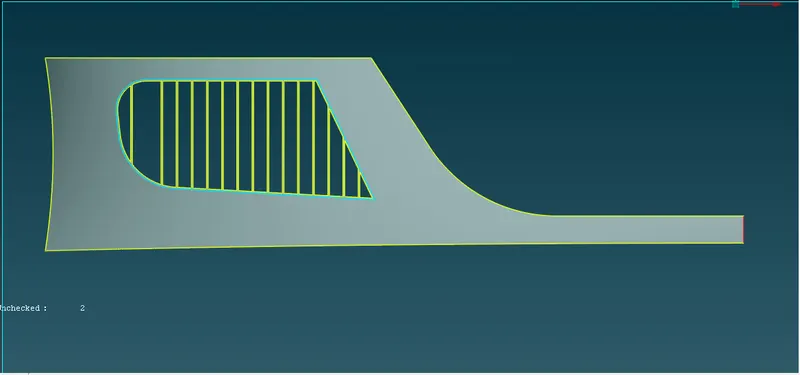
21.also the grills are not properly align
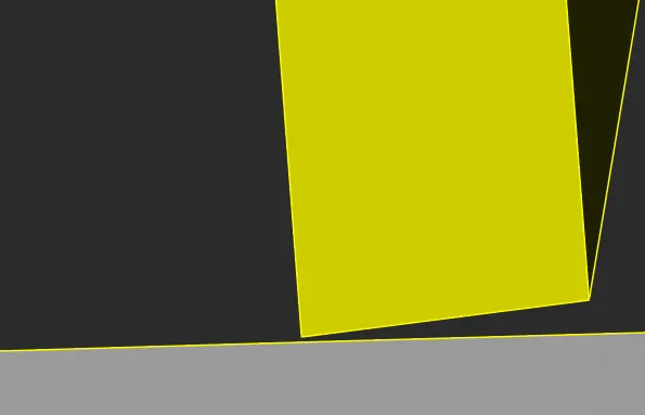
22.so we will create an another face at .2mm distace from older face (first create hot point with refrance to older using peremeter hot point and after that we will creating hot points we will create new surface using cut option )
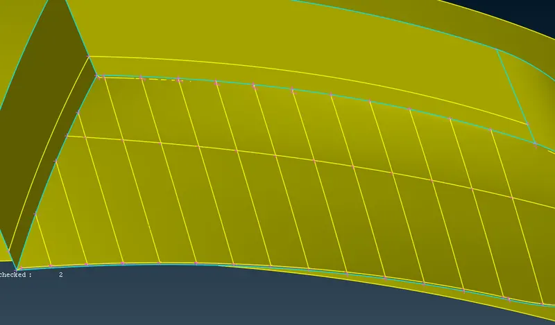
23.after creating cons create surface by selecting cons and midddle click
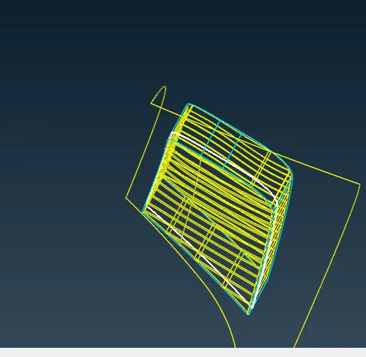
24.after creating new surface intersect new surface with older grill and delete all the small surface and solve all the triple cons by deleting unwanted surface and geomatrical ceck and when we found no error in grill we can go for another 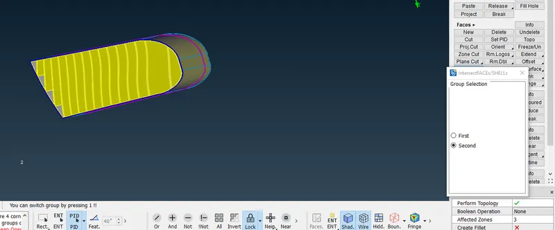
25.after clearing all geomatrical error taking another part
we will take headlight we can see taht triple cons are present on headlight so we have to cler all the triple cons by deleting all the extra surface and unwanted surface for deleting extra surface hide the upper part of headlight and delete all surface because we need only outer part
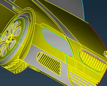
26.after deleting all faces in headlight we will create a new surface using new faces + cons
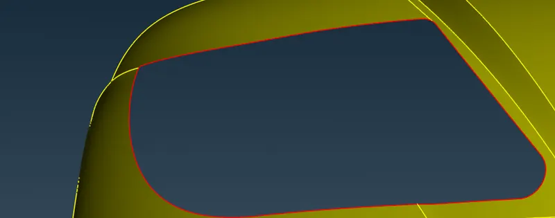
27.after clearing all geomatrical error check geomatrical error and the final face will shown as in below fig
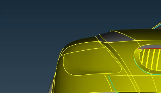
28. taking another grill for geomatrical error and intersection error
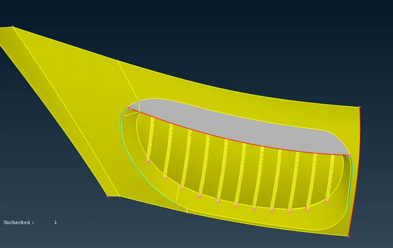
30. deleting extra surfaces and filling the surface
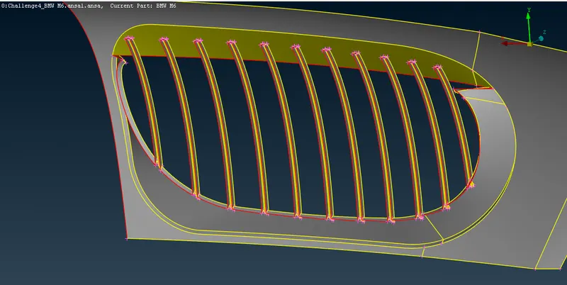
31.using plane cut the cons are formed on another surface
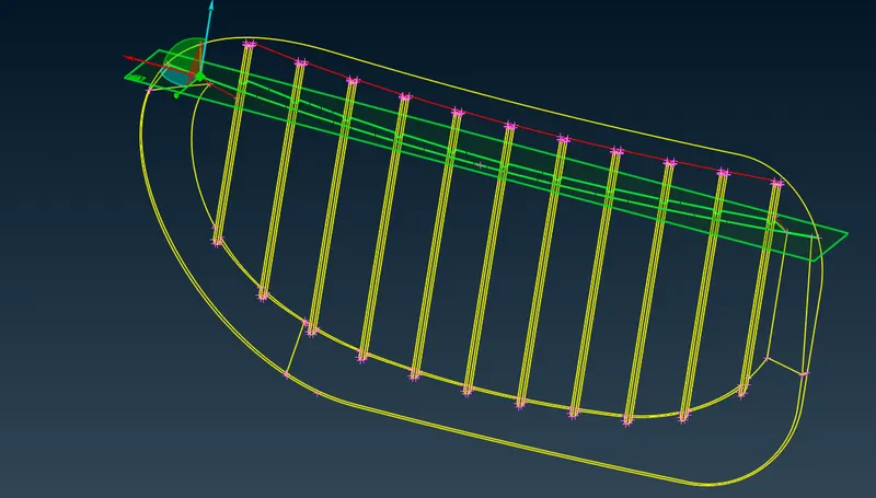
32.when cons are project delete the upper part that are not desired and fill the blank surface by creating new surface
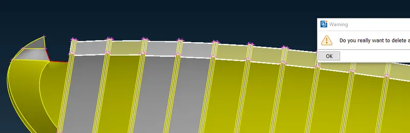
33.taking another part
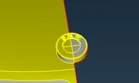
taking logo
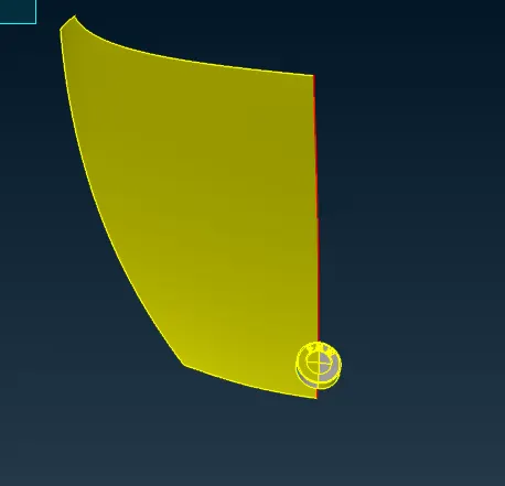
34.deleting the below surface aND KEEP only upper part
35.taking the windsheld part and and after checking we found that there are one or more surfaces present
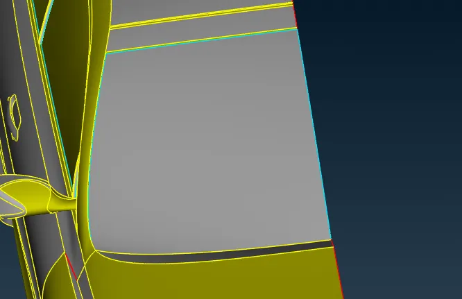
36.after deleting the extra faces all triple cons are also gone
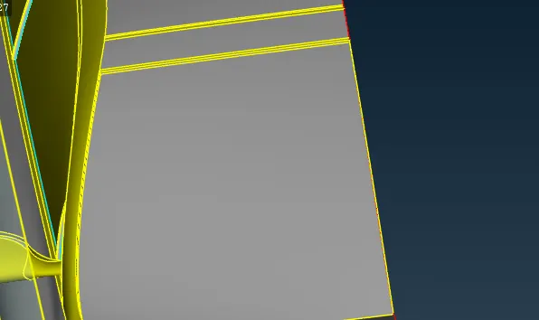
37.taking the window part and we can see that there are triple cons are present and after checking we see that there are two or more faces are present after deleting extra faces all geomatrical error are gone
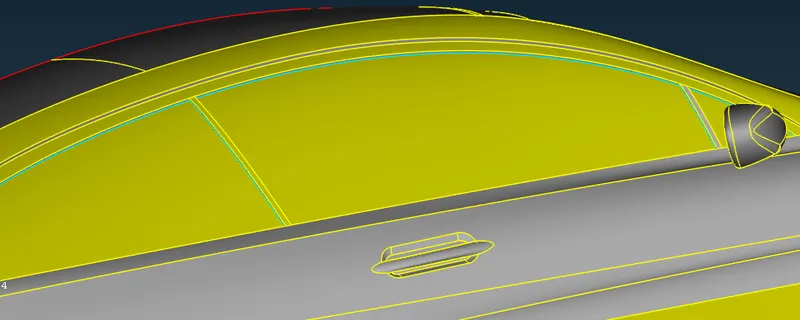
38.rear light
triple cons are present and after checking we found that there are two or more faces are present after deleting extra faces all geomatrical error are gone
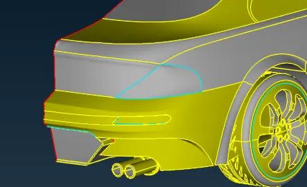
39.side grill
first we delete the face that we dont required
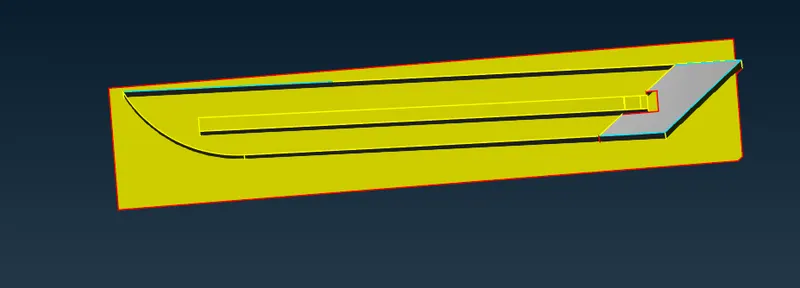
40. after deleting the face we can see that there is gap present between the faces to fill the gap use extend face and select side of cons which will extend
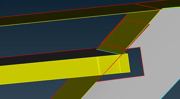
41. after extending faces we can see that the cons are formed are not complete so we will extend con by cut option
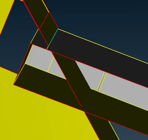
42.when proper con formed we will delete the unwanted faces as shown in fig

43. surface are not joined properly so for joing proper surface we use intersecting surface after intersecting surface deleteing another part
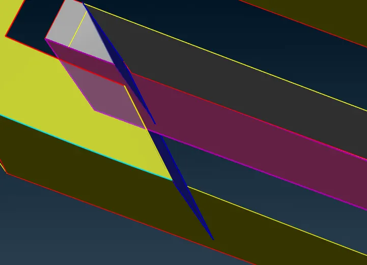
44.in below fig we can see that the surface are not fine and not properly join
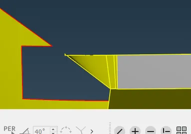
45.deleting the faces and we see that there are unnessasry hot points so by deleting the hot points we get a proper surfaces
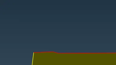
46after geting the proper surface create a surface using new faces and middle click after creating the face we see that there are some extended surface so we need to delete the extended faces
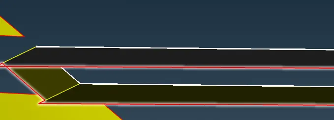
47.create a son on extended surface and seprate the surface to be delete and after seprating the surface delete the face by universal delete option
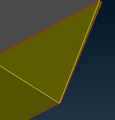
48.by hiding the faces we see that there are some hidden faces delete the faces by universal delete
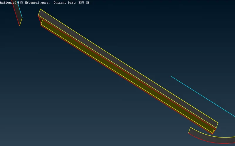
49.after deleting the faces close the surface by new faces
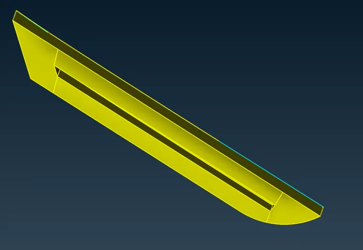
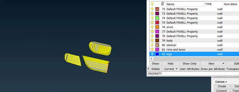
50.there is small gap present in model compelete the gap using fill hole
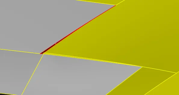
51.in below fig see that there is triple con present in surface clearing triple con by deleting extra surfaces
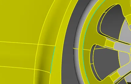
52.the floor of bmw is also not clean and triple con are present in surface and the surface is also overlap we need to clear floor surface and deleting overlaping surface
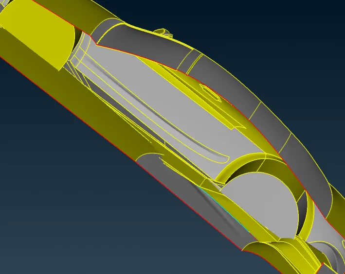
53.first we create curve for refrance
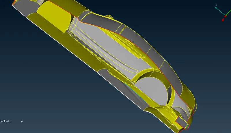
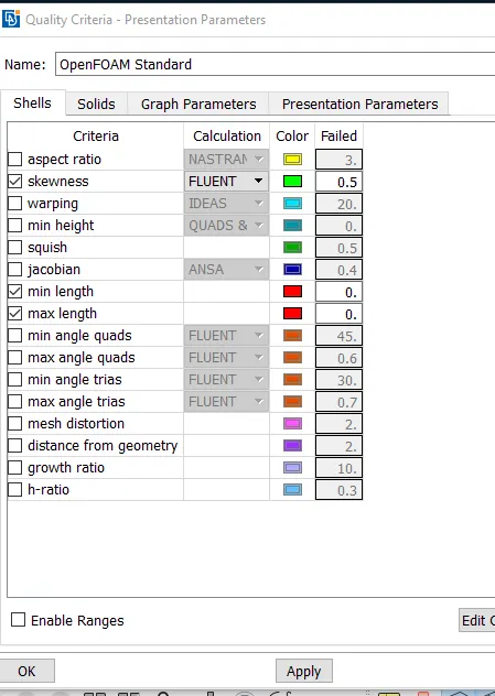
54.from below fig we can see that there are extended surface aslo present so we will delete the extra extended surface by universal delete
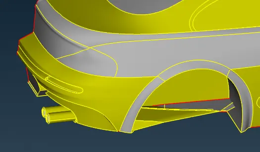
55.for extra intersecting surface we will intersct both surface and when seprate surface are formed delete the extra surface and also for floor surface delete all the floor and create a new floor by new face option
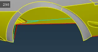
56.after clearing the floor surface will be show as shown in below fig now the floor is clear with triple con and there is no extra overlaping surfaces
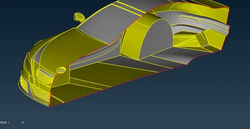
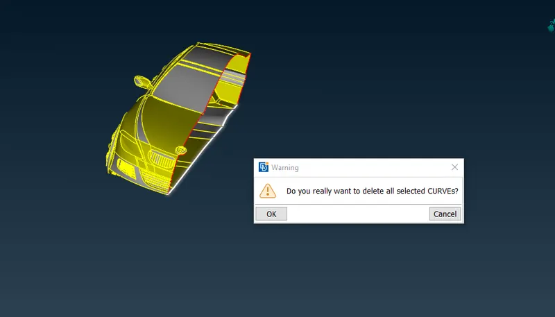
57.after surface cleaning delete the refrance con that we formed
58.tyre and rims
from below fig we can see that there are triple cons present in tyre so for deleting the extra surface hide outer surface and delete the faces that we dont want
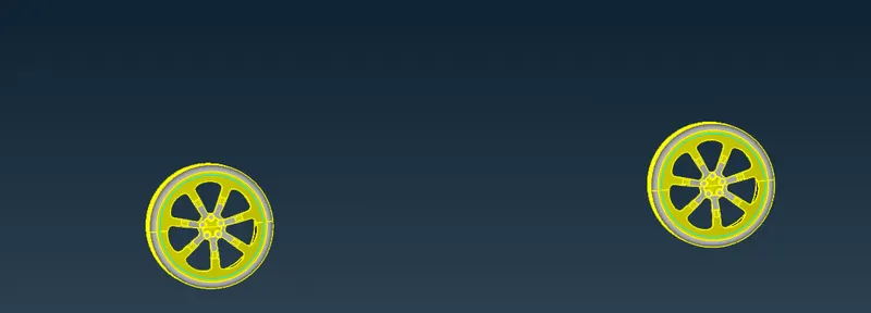
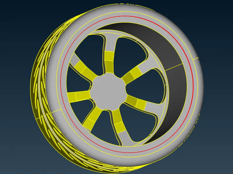
59.after deleting the extra surface single cons are formed so we delete the small surface also and create a new sorface after clearing all error and deleting the overlaping surfaces geomatric check
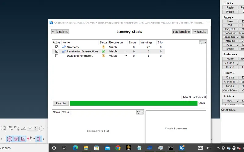
60.after clearing all single cons and triple cons geomatric check for all model when no error from geomatric and intersection we can do surface meshing
61.before surface meshing asigening pid for model and checking pid
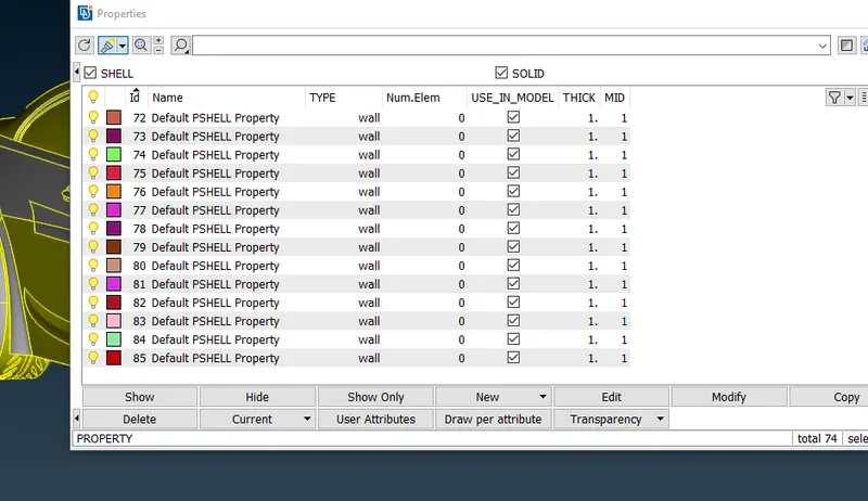
62.pid name asign as below :
1.body
2.tyres and rim
3.orvm
4.mirror
5.lights
6.logo
7.silecer
8.grills
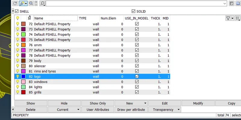
PID ASSIGMENT
63.now we have to asign pid for parts
1.first for grill isolate all grills and then for asigning grills pid select all grills then middle click
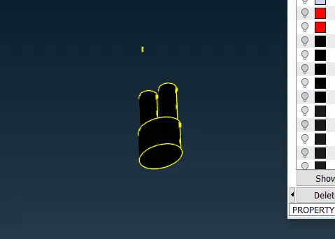
64.same for silencer right click on silencer in pid then isolate silencer and select silencer then middle click
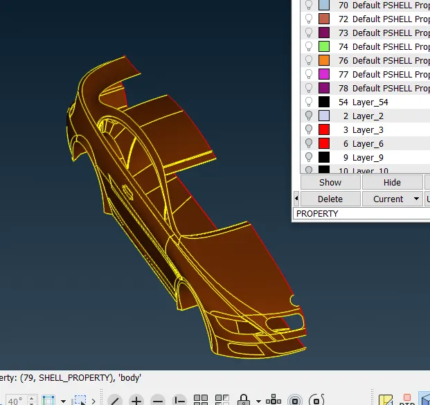
65.same for body right click on body in pid then isolate body and select body then middle click
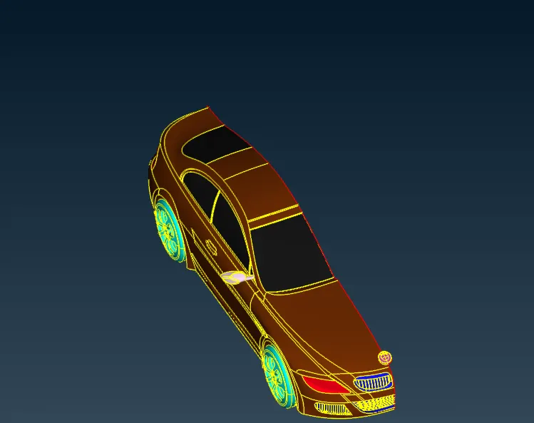
66.after asigning all pid the final the final model seems to be as shown in below fig
67.after asigning all pid check for quality criteria acording to requirement
SHUFACE MESHING
68.the target length for surface meshing
- Body - 3 mm
- Lights - 4 mm
- Grills - 1 mm
- Rims and Tyres - 2 mm
- Optical Rear view mirror - 2 mm
- Window - 2 mm
- Silencer - 3 mm
- Logo - 1 mm
68.for surface meshing
1. taking the grills and logo for together the target length for grills and logo is 1mm so give
min length=.5mm
max length=1.5mm
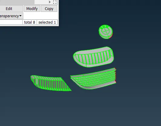
69.after meshing we can see that there are some ofset surface are form to reduce the ofset surface right click and then select reconstruct then ofset surface get reduce
after meshing frezze all the elements
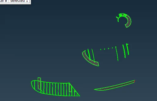
70.taking the window and tyres&rims for together
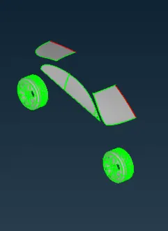
71.the target length for grills and logo is 2mm so give
min length=1mm
max length=3mm
after meshing the surface will show like below surface
after meshing frezze all the elements
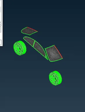
72. isolating body pid
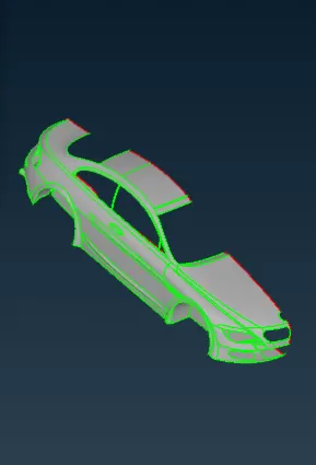
73. the target length for grills and logo is 3mm so give
min length=2mm
max length=4mm
after meshing frezze all the elements
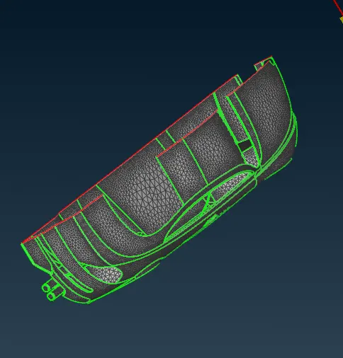
74. taking light pid the target length for grills and logo is 5mm so give
min length=4mm
max length=6mm
after meshing frezze all the elements
75. the final surface will be shown as below figure of surface meshing + frezze
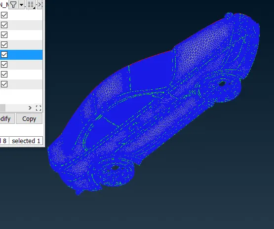
76. after meshing create another half part of bmw using copy option from transform and select 3 potint symatry and select 3 points from the model and middle click( keep logo hidden because we mesh complete logo)
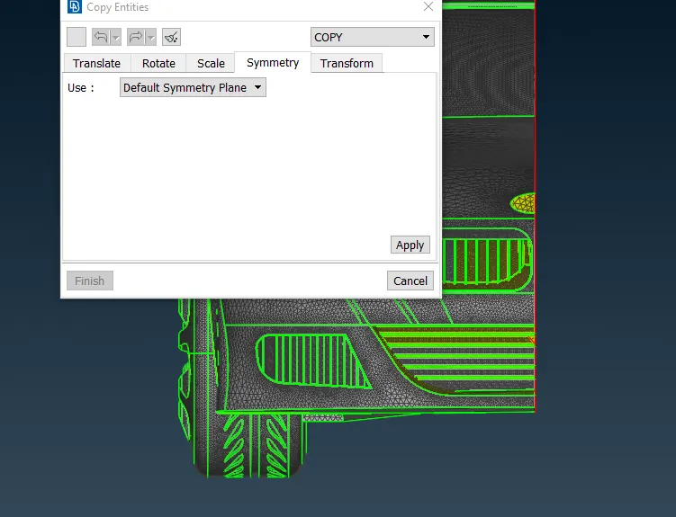
77. after creating the half part of bmw we can see from photo that there are single cons are present so to remove single con hit a topo and all single cons are gone
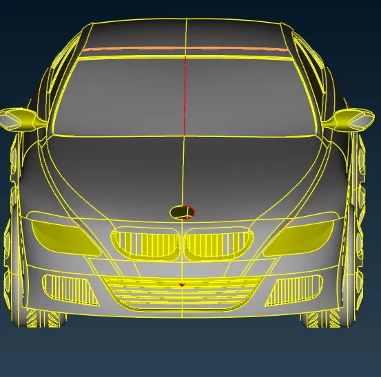
WIND TUNNEL
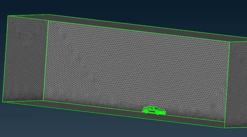
78.after creating the half part of bmw and removing single cons create wind tunnel in such a way that tyre of car does not touch the surface of wind tunel and lets lenght of car is X
the distance of front face of wind tunel is 4X from front of car
the distance of back face of wind tunel is 6X from back side of car
and the distance of side face of wind tunel is X and X from side of car
the distance of top face of wind tunel is 3X from car roof
respectivly
messure the total length of car X=1307 or~1300
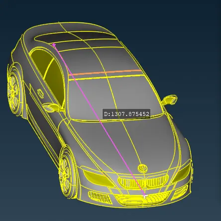
79. taking point for refrance in middle of car X/2=631~650
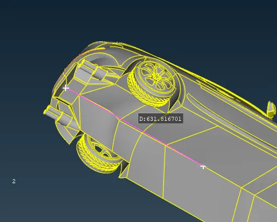
80.create a point from our refrance point below the car with relative in points at the distance of 200
and with refrance with this point create the point
front of car=4*1300+650=5850(650is the half distance of car)
back of car=6*1300+650=8450
side points will create with refrance of front and back points at the distance of X = 1300+400=1700
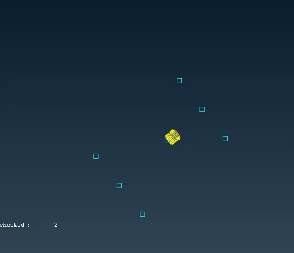
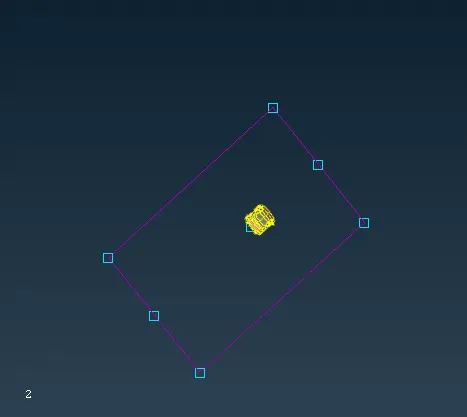
81. when the all points are created we will create curve and using this curve create a new surface
82. marking a point above the car roof at the hight of 3X and messure the distance between the points and make plane at the hight of4111 with refrance of 1 point using offset
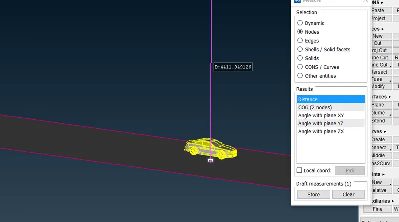
83. after creating the upper surface cteate the side faces using single cons
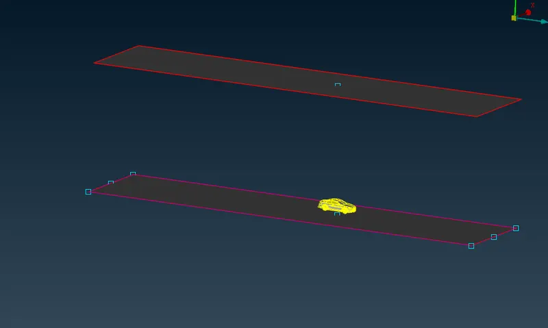
84. when all faces are formed difine pid names for all surfaces
bottom surface for bottom
top face for upper face
side face for all side face
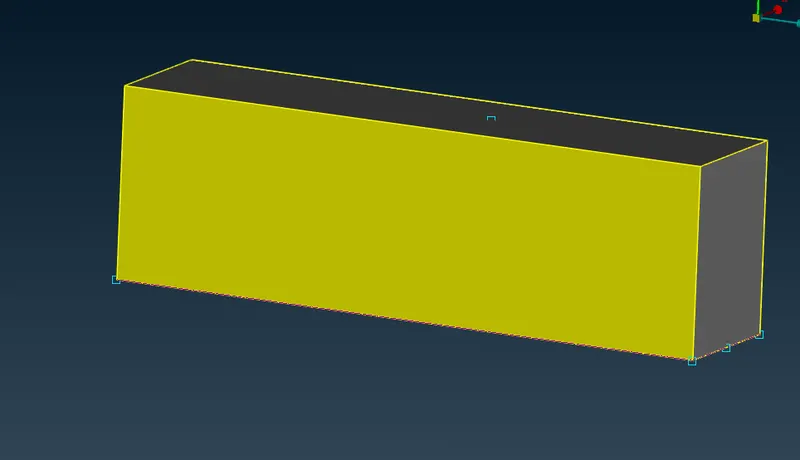
85. delete the curve we created
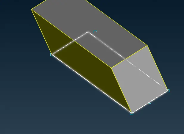
86. delete all points we created for refrance
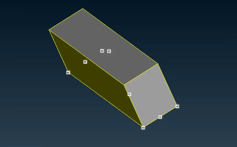
87. after pid asigment mesh the faces
for bottom surface
target length=20
minimum length=1
maximum length=30
for top surface
target length=100
minimum length=90
maximum length=110
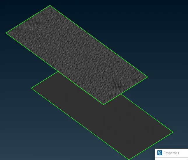
88. for side faces we use growing mesh by seleting manual from specing
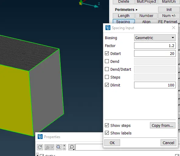
89. the meshing of wind tunnel is complete
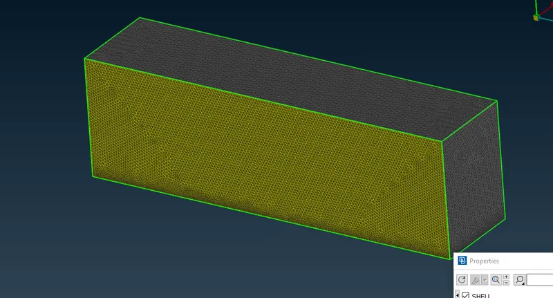
90. FINNAL RESULT