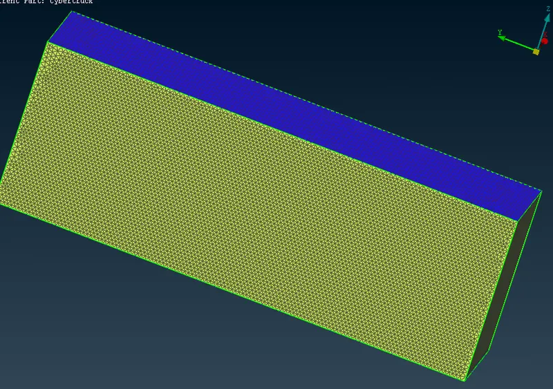
Project 1 : CFD Meshing for Tesla Cyber Truck
AIM: For the given model, check and solve all geometrical errors and Assign appropriate PIDs. Perform meshing with the suitable Target length and element Quality criteria.
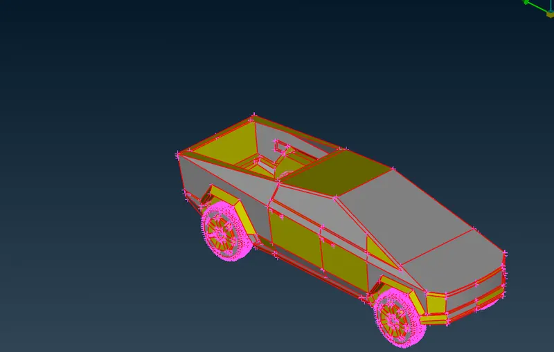
procedur:
1. from the fig we can see that there are all single cons present
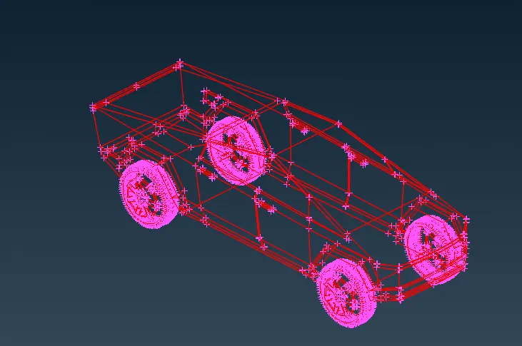
2. so to remove single cones we do topo for hole geomatry. by doing topo all unjoined cones will join and actual single cones will left so we have to remove all single cones from geomatry
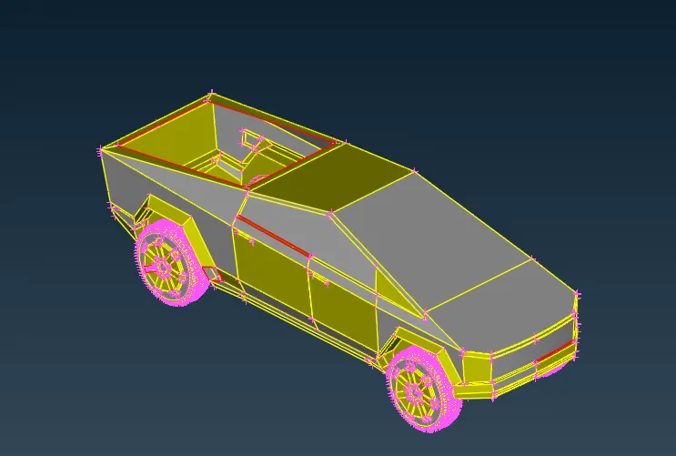
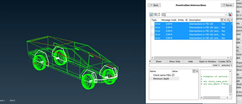
3. from geomatry check we can see that there are intersections error are also present in model the highlight surface shows the intersection error present in model
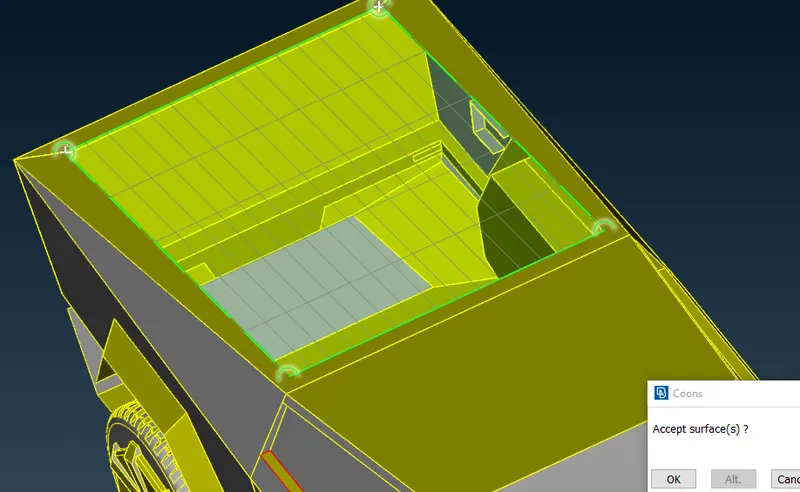
4. first we cover the back surface using new surfaces
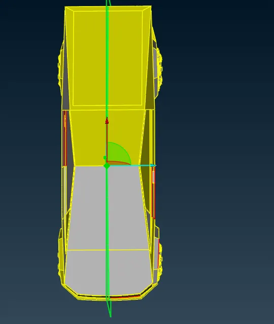
5. after creating the surface we can delete half part of the car because the car is symatric so we will devide the car using plane cut.By plane cut the cons will project on the all surface
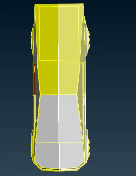
6. after creating the cones we can easly delete half surface by universal delete
7. after deleting the half part of model remove allthe error in half part of model
from below fig we can see that there are uncover surface present to first create surface using new surface
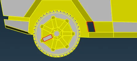
8. from below fig we can see that there are small surface present which can create error in meshing so we have to delete or reomve that small faces
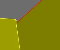
9. single small surface cannot delete so we have to delete a part of model including small faces so to delete a part seprate a part using a cut option and delete by universal delete and create a new surface using new surface and do same for both side
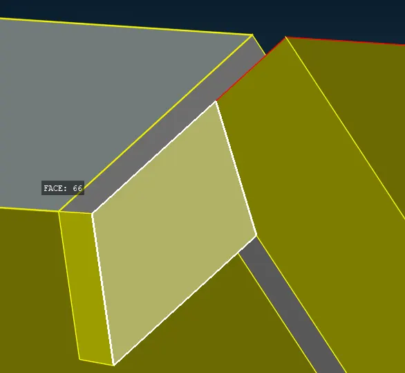
10. delete the window part also because it is not proper aligen
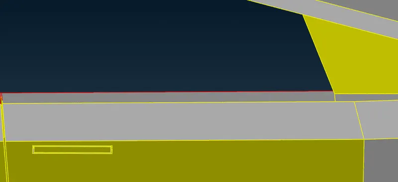
11. and we can see that the part near the window is also not proper so delete the part and create a new surface
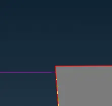
12. create new surface by using new faces
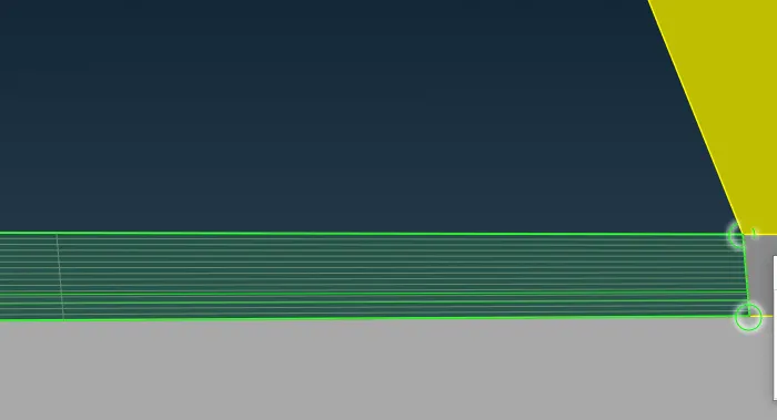
13. create new surface by using new faces for both surface near window and window
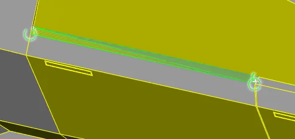
14. after createing the window part check for geomatric check and we can see that there is only single cones present on half part of model
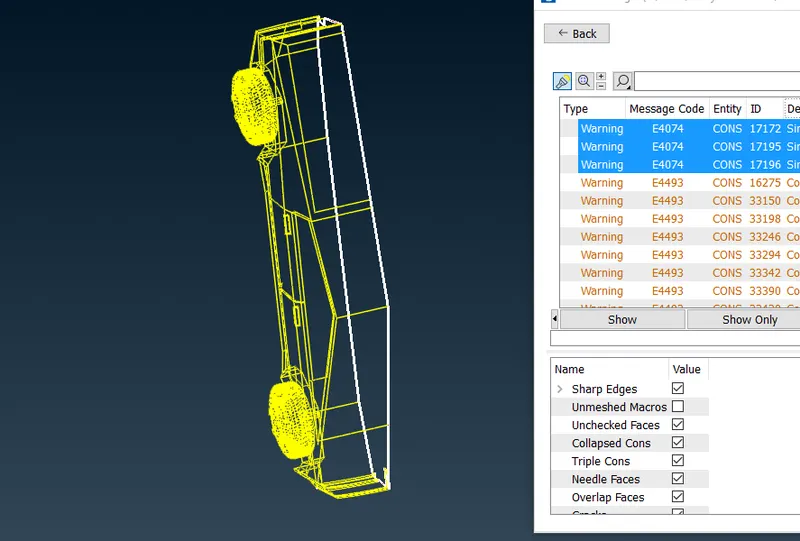
15. from intersection error we can see that there are intersection error in front part of car so while checking we found that there is overlaping surfaces
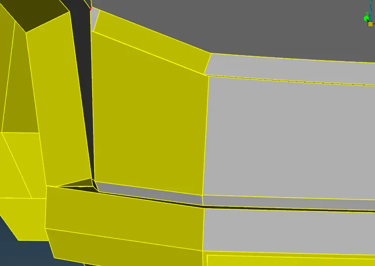
16. from below fig we can see that there are overlaping suraces so first we will delete the hole overlaping surface
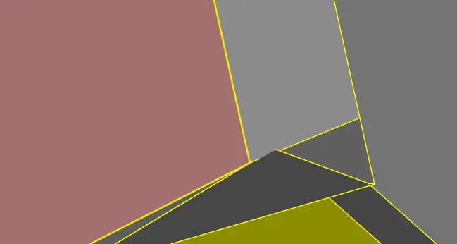
17. after deleteing the surface we see that there are surfaces present which are not proper aline so we delete those faces also

18.check all faces and delete all overlaping faces
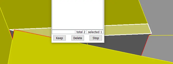
19. after deleting all faces we create a new face by new faces and selecting new cons
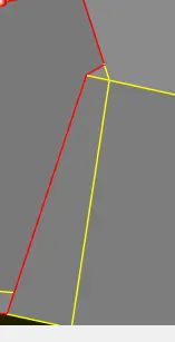
20. after creating new faces check for intersection error
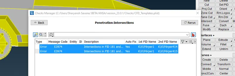
21. afer checking intersection error we found that there is error in shaft of car so we can see that there are two overlaping surfaces are present so we have to delete one of the surface by universal delete
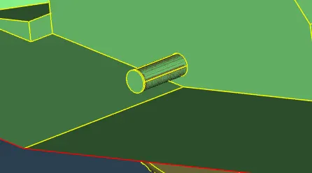
22. so select the brown surace( tyre part ) and delete it
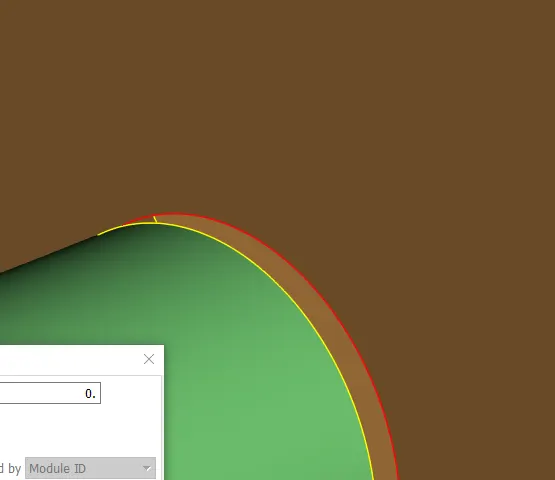
23. after deleting the tyre part we can check there is no intersection error present so do the same for other side also
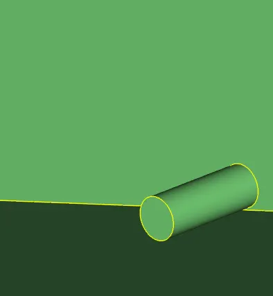
24. and after deleting the overlaping surfaces from both side we have to check for geomatry check and found that there is no intersection error present
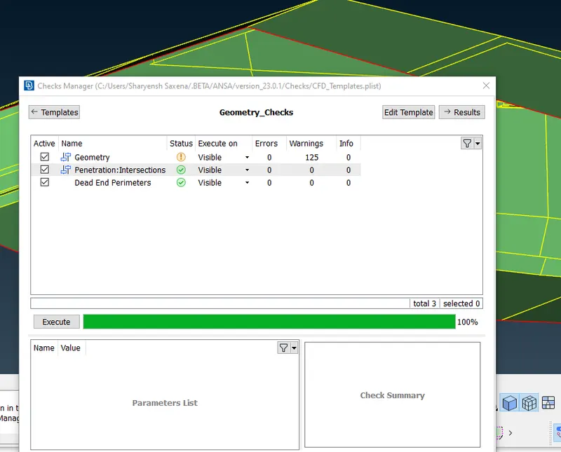
25. after clering all gematry error and intersection error check for pid and asign pid
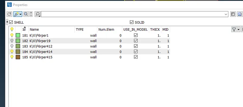
26.asign pid name as
1.body
2. mirror
3.tyres
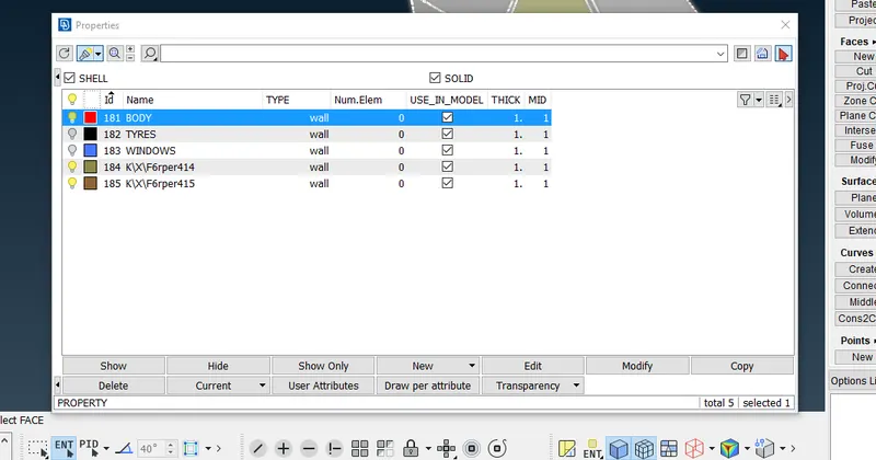
27. when we done with asigning pid names asign pid in model for all
asign pid for window
so for window right click on window pid and click apply and select window and middle click
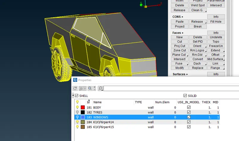
28. asign pid for body
so for body right click on body pid and click apply and select body and middle click
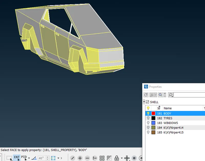
29. asign pid for window
so for window right click on window pid and click apply and select window and middle click
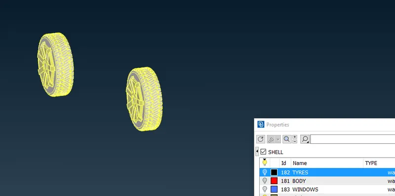
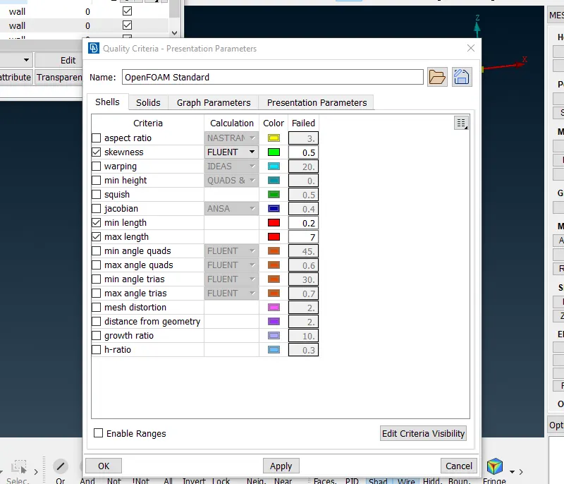
30. after asigning pid in model check for qualiy criteria and keep quality cretria according to reuirnent for meshing
give
minimum length=0.2
maximum legth=7
for complete model
31. MESHING
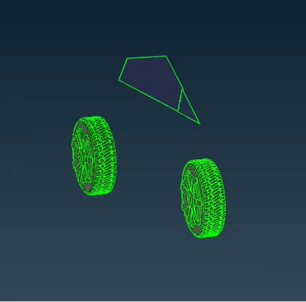
take mirror and tyres together because we take both target length as 2 mm so
select auto cfd and give
minimum length=1.5
maximum legth=2.5
for parameters and macros and cfd visible
and frezze all element
32. for body target length=3
select auto cfd and give
minimum length=2.5
maximum legth=3.5
for parameters and macros and cfd visible
and frezze all element
after by selecting all the model wil lock like below fig
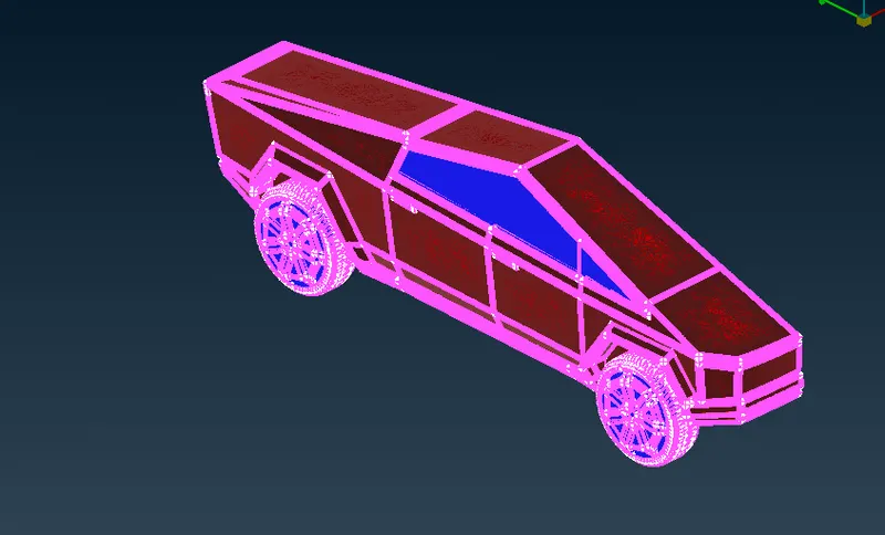
33. after meshing mirror the other half part of car using symatry 3 points and select point on which refcrance we have to symatry other part of car
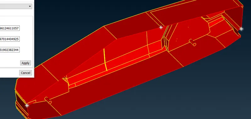
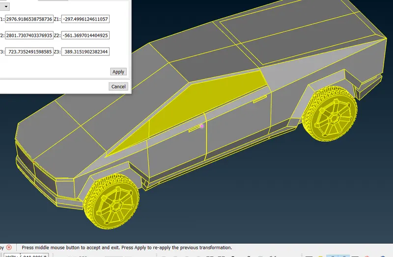
34. after selecting click apply and middle click and the other surface is also created and after creating the complete model check for geomatry check that there are no error in surface if there is any error then resolve it
35. CREATING WIND TUNEL
for creating wind tunel we take the dimensions as
lets X is total length of car
for bottom surface = that does not touches the tyre
for top surface = 3X distance form roof of car
front face = 4X distance from front face of car
rear face = 6X distance from rear face of car
side face = X distance from side of car for both faces
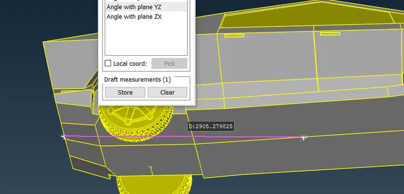
messure the total disance of car (X) =5754~6000
for creating bottom surface = that does not touches the tyre
we take a refrance point at distance of 1000 frm the bottom surface of car
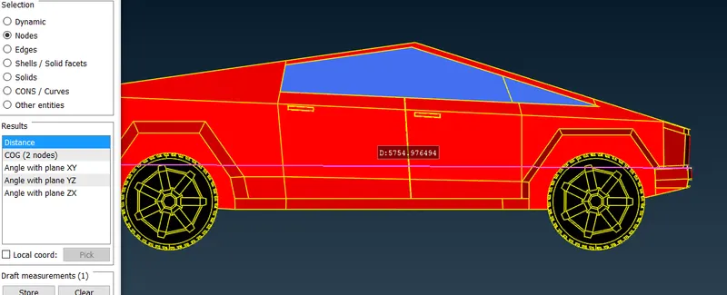
36. messure the half distance of car = 2905~3000
37. create front and rear points with refrace of bottom point we created
front face = 4X distance from front face of car + half distance of car
4*6000 + 3000 = 27000
rear face = 6X distance from rear face of car + half distance of car
6*6000 + 3000 = 39000

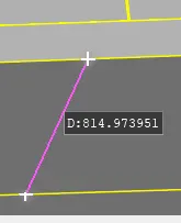
38. for creating side faces messure the half distance from bottom of car for creating side faces 814~1000
side face = X distance from side of car for both faces + half distace of car
6000 + 1000 = 7000
for both sides of car
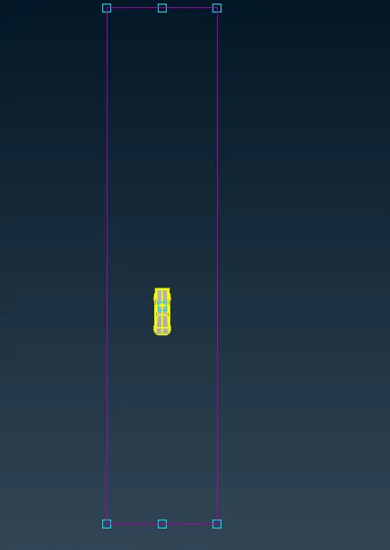
39. after creating the side faces create cons for refrance using cones to project
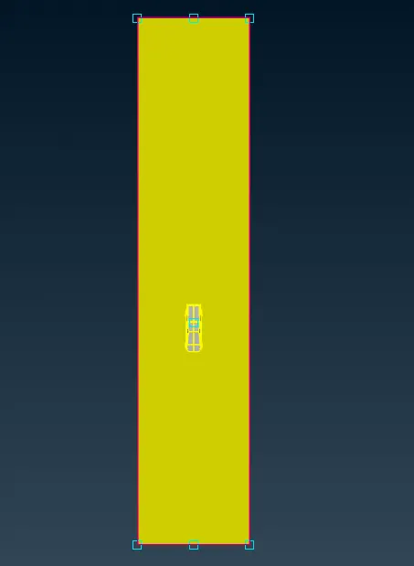
40. after creating cons for refrance create new faces using new faces with prjected cones
41. for creating top surface create a refrace point at distance 3X distance form roof of car = 3*6000 = 18000
and mesure distance of refrance point from bottom surface is 23379 and create top surface using offset at the distance 23379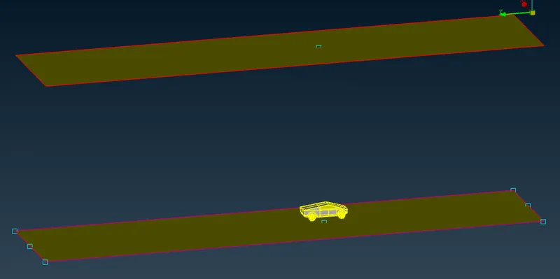
42. after ctraeting the top surface create side faces using new faces with refrance of top and bottom surface cover all sides of wind tunnel
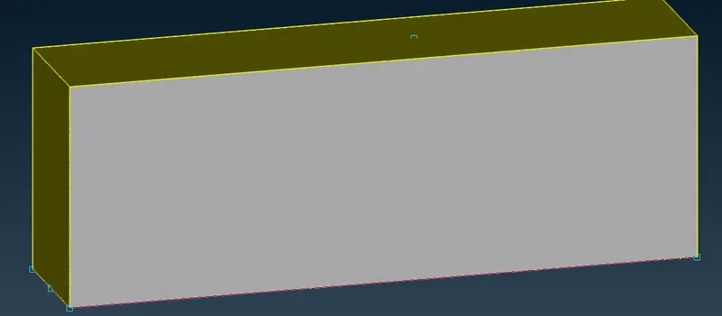
43. after creating wind tunnel delete projected coes which created for refrance
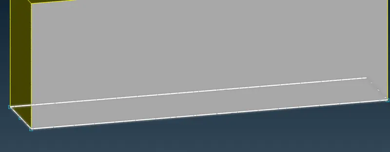
44. and also delete all points which we create using universal delete
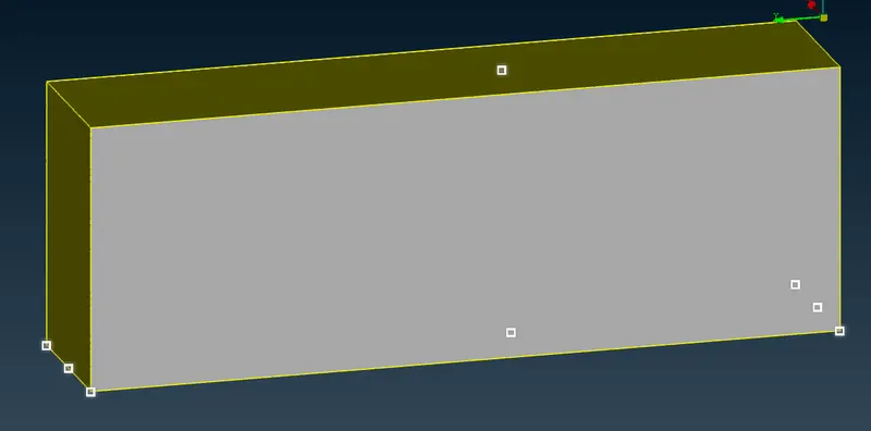
45. MESHING OF WIND TUNNEL
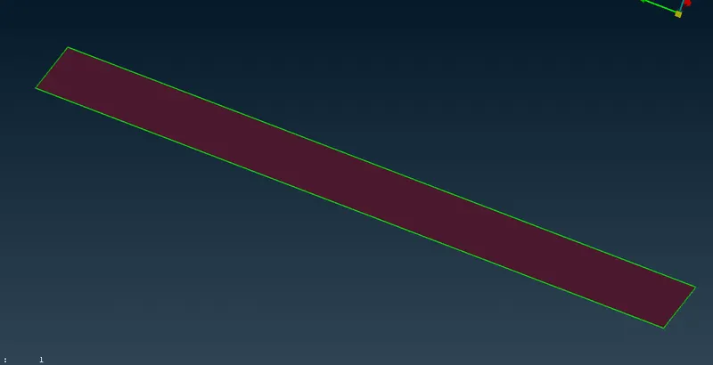
after ctraeing wind tunnel taking the bottom face
for bottom faces target length = 500
using specing> auto cfd give
minimum length = 490
maximum length = 510
and cfd visible and afer meshing frezze all elements
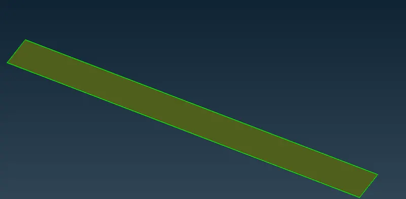
46. for bottom faces target length = 650
using spacing> auto cfd give
minimum length = 640
maximum length =660
and cfd visible and afer meshing frezze all elements
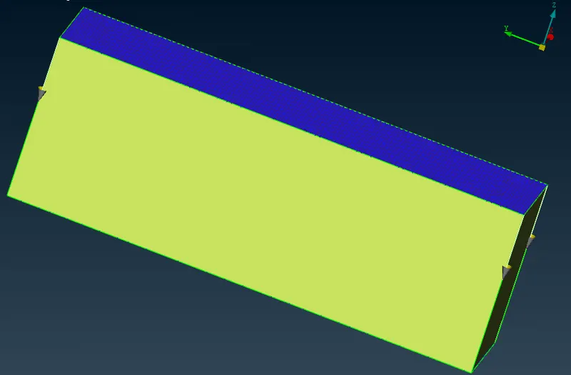
47. and for side faces we use grow mesh using spacing> manual
and give dstart = 500
dlimit 650 and select the faces and then cfd visible and frezze all element
48. FINAL RESULT