Week 3 Challenge : CFD meshing on Turbocharger
AIM; For the given model, check for the geometrical errors to make appropriate volumes. Perform surface mesh with the given target lengths as per PIDs. and Perform Volumetric mesh for the required volumes
Procedure :
1.we have given a model of turbo charger a shown in fig
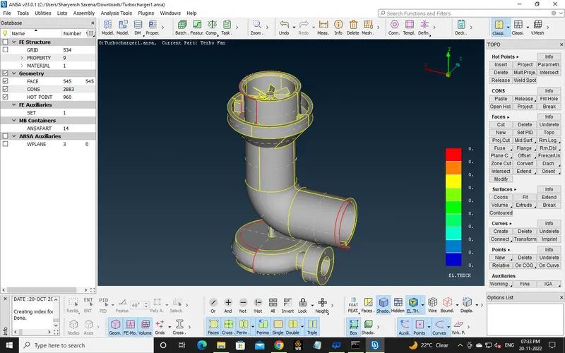
2. for the given model we have to perfome surface meshing and volumeatric meshing so first of all we have to clear all the geometrical errors from the model
3.we can see that an over lapig surface on the green surface of turb charger so we have to delete that pink colour surface by selecting delete option and then select the pink colour surface then delete
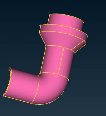
4.now we can see that an extanded surface and a red con are on selected surface so we have to delete that surface and create a new surface
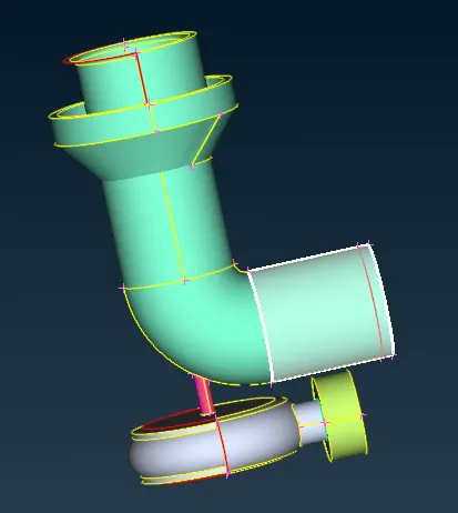
5.after deleting the extanded surface the surface wil see like this as shown in fig then we have to create a new surface by selecting new> cons +loop open then middle click
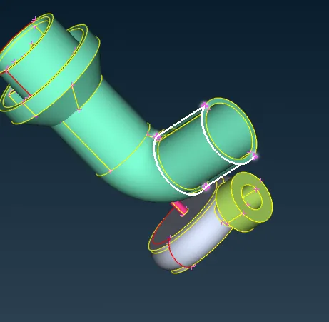
6.then we have to check the geomatry check and as in fig we can see that the red cons which are causing error
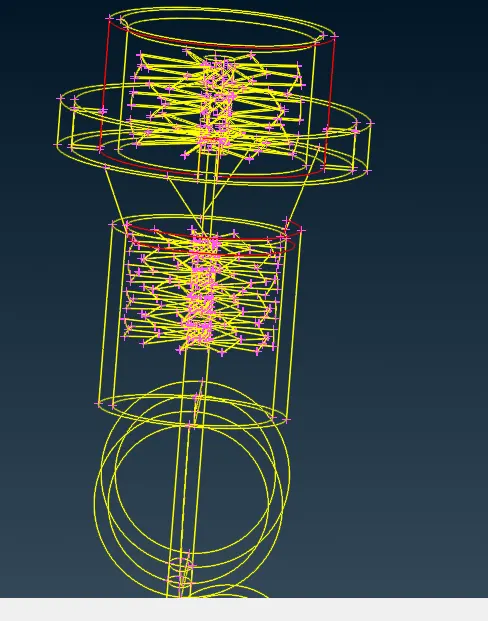
7.the red con which is in middle of the fig are form by the interction error to to remove error we use intersection option and then first we have to select the first surface and middle click and then selecting second surface and middle click
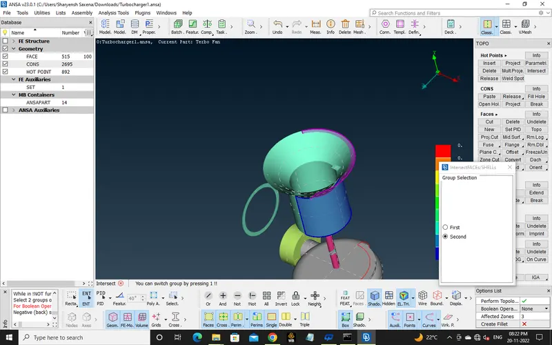
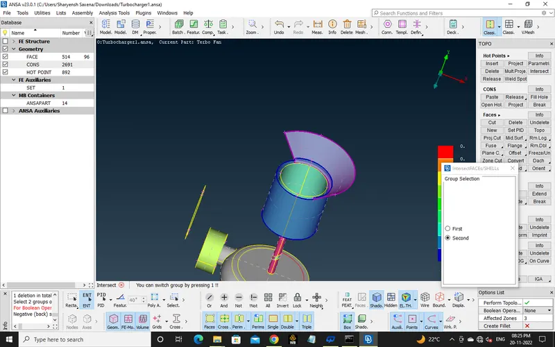
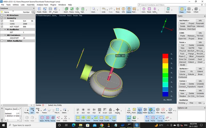
then select the surface we want to keep and delete the surface we dont want
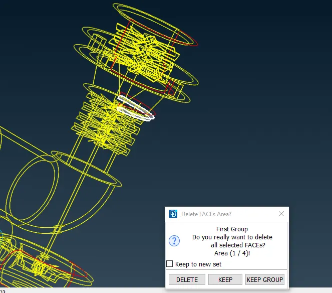
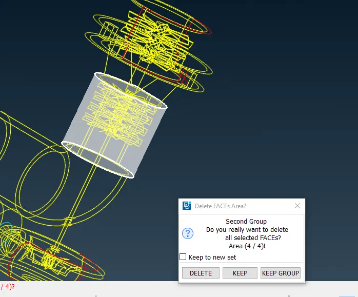
8.select the cut option and make a straight cut and delete the small surface and big surface too and create a new and fine surface
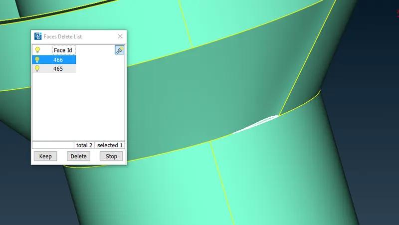
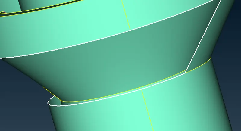
9.using transform option first we have to select the curve we have to create surface along
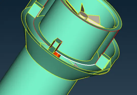
then we have to select hot point along which we have hto create the surface
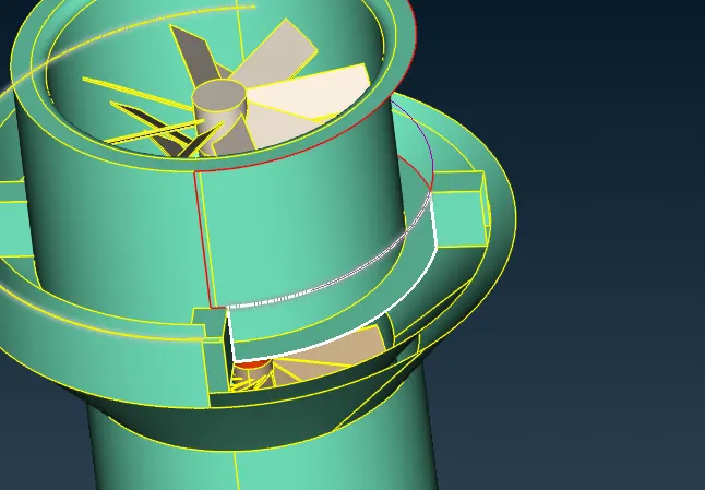
both side same method will use
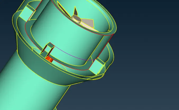
after creating the path we have to select the new surface +loop option and then middle click
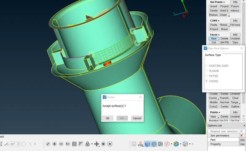
again select the new surface +loop option to create the surface
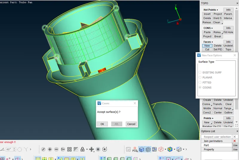
after creating all the surface we can delete the curve we created by selecting delete option from curves and middle click
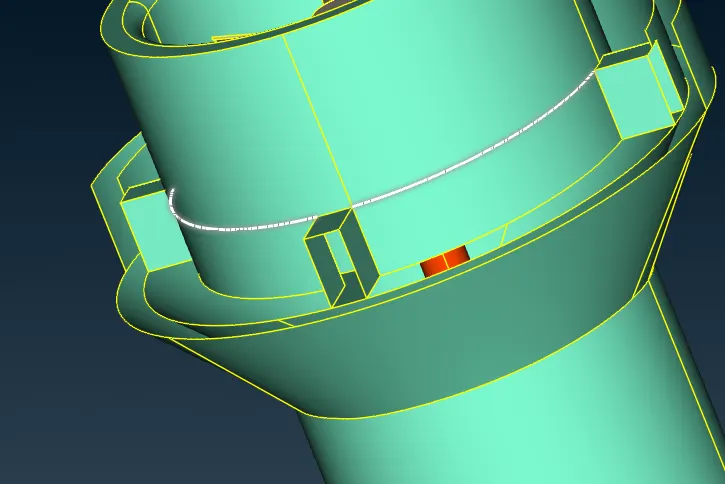
10.then we have to clear the red con as shown below in fig
for creating new surface we select copy option from upside and then select the surface to be copy and then middle click then the page will open as below then select symitric option
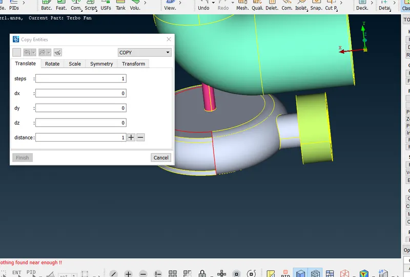
then select the hot points on the axis along which we have to copy the surface
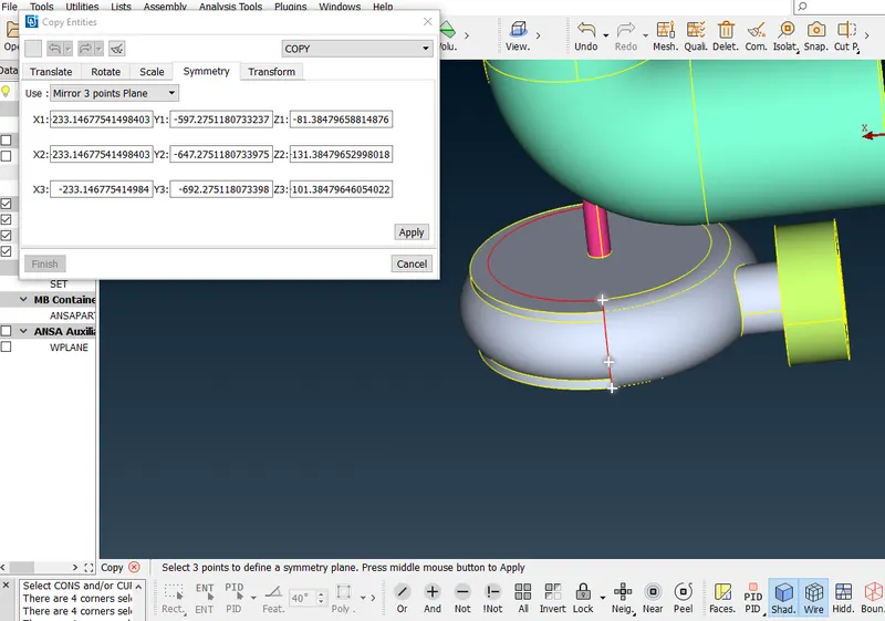
then the surface is formed and a middle hole will form the hole will form by fill hole option
11.after cleaging all geomatrical error we have to check if there is any geomatrical error present or not when all geomatrical error reomved
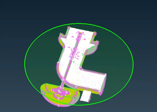
12. check for intercection error as shwon in below fig the error are show in like this way
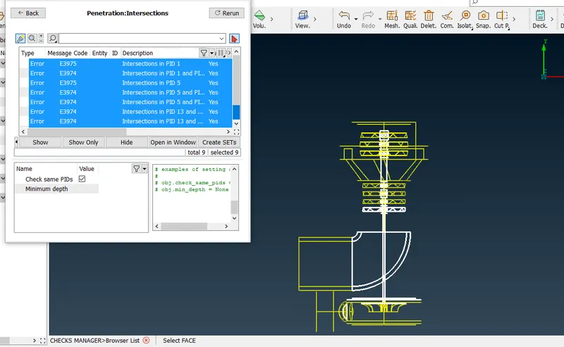
13.selecting the shaft part only and do toppo first so all cons join properly for topo select topo and box select and then middle click
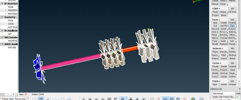
14.after topo we can clearly see that all cons are joined and double cons and triple cons are foromed
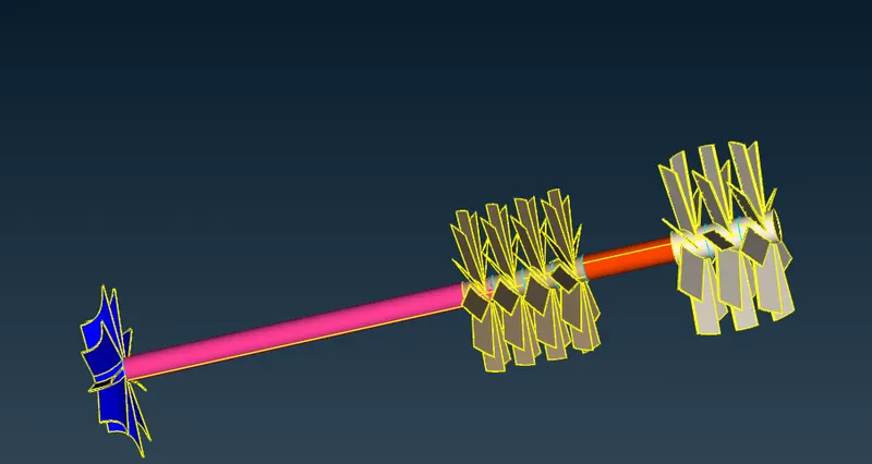
15. we can see that tere are triple con and the triple con are formend because there are two or more then two surface are joining so we have to delete the surface onw by one
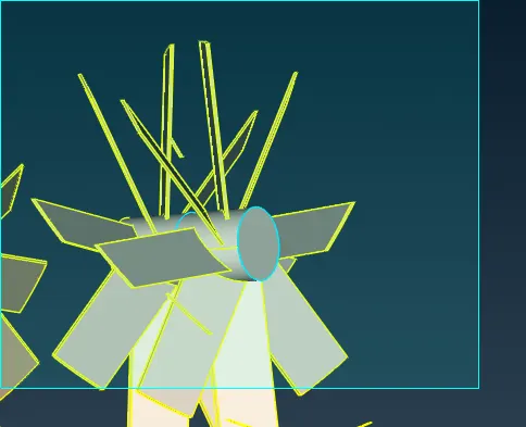
16 so while deleting the surface we can we that there is diffrance in diameter of both diffrent pipes so we have to fill the surface by using new cons option as shown in fig
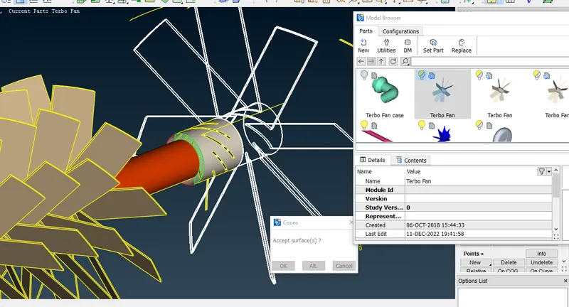
17.now as shown in fig we can see that there are two diffrent surfaces are overlaping so we have to delete one of the surface
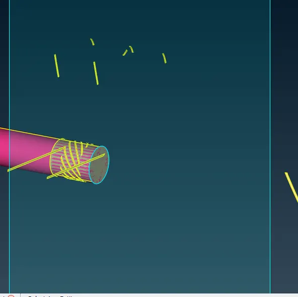
18.we cant delete the blade part so we will delete the shaft part . so to delete the shaft part we have to seprate shaft part because if we select delete option and then delete shaft it will select hole shaft so to seprate shaft we have to select project cons option and select the con that to be project and then middle click and then select the surface on which con should be project
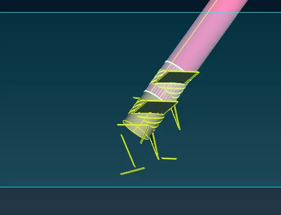
19. as shown in fig the shaft s now divided in two parts so now we can delete the small part of shaft by selecting the delete option and then selecting the part to be deleted and then middle click
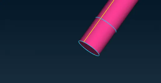
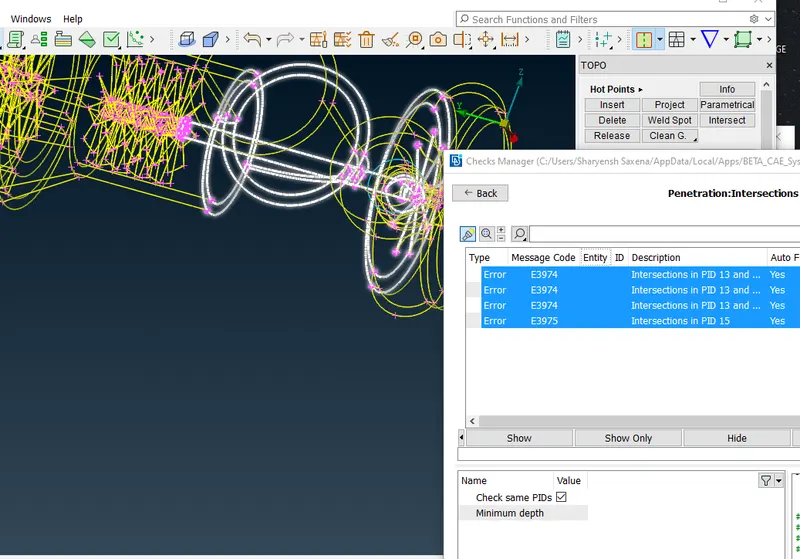
20.after deleting the shaft part again geomatry check and see the intersection error. as shown in below fig all inersection error
21.we can see from below fig that tere are two surface are overlaping surface so we have to delete the overlaping surface by selecting delete and surface to be delete and middle click by this green colour surface is delete
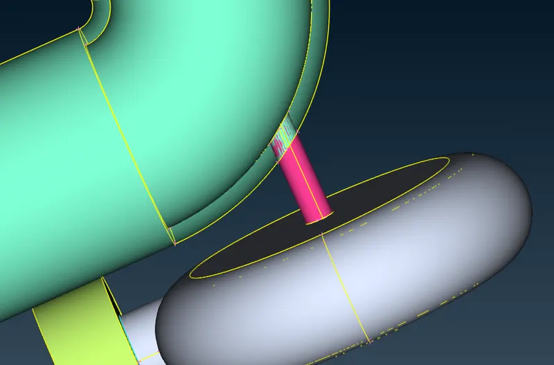
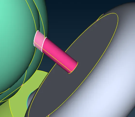
we also have to delete pink colour shaft and to delete shaft we have to seprate a part of shaft by projecting cons and midle click and select the surface on which cons should be project when cons formed we can easily delete the shaft part by selectig delete option
22. after clering all intersection erroe from shaft we have to check again intersection error and rest of intersecion error are shown in fig below
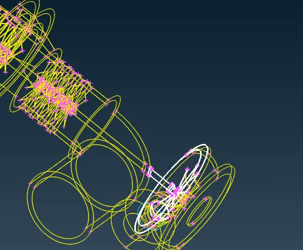
23.so we can see in fig that there is also intersecting surface present so we have to delete intersection surface
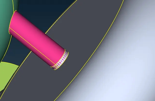
we can delete the gray surface eassyly by selecting delete option as shown in fig
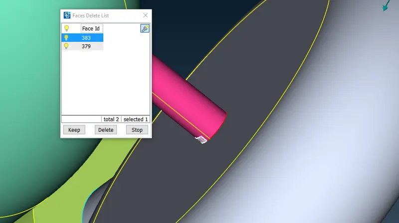
we also have to delete the shaft part also by projecting cons option and when cons are form we can easstly delete pink shaft part as shwn in fig below
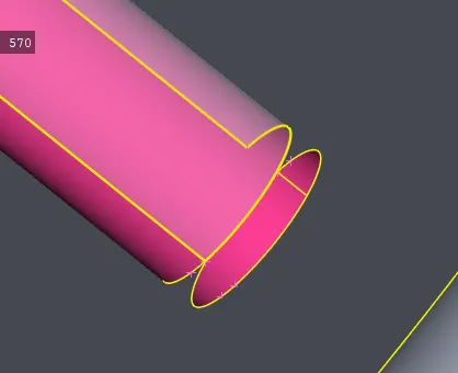
23. after deleteing shaft part we have to check again intersection error and the remaing error are shown in below fig
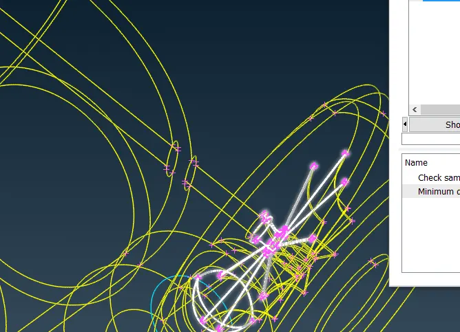
24.as shown in fig the intersesion error are shown in below fig
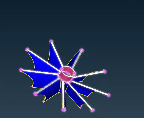
as from below fig we can clearly see that two intersection surfaces
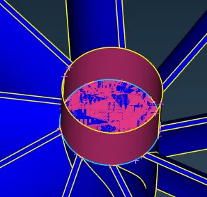
25. so we have to delete both te surface to delete blue surface we have to project con on blue
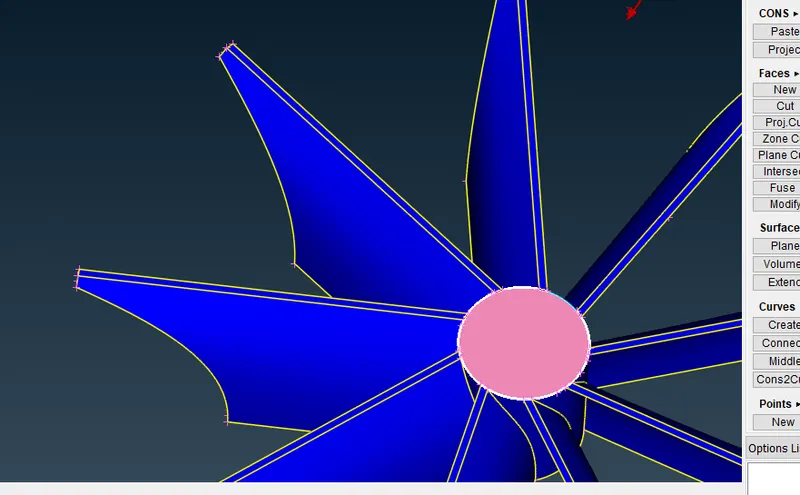
26. when both surface deleted it will show like below surace
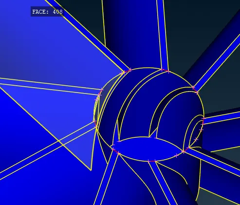
27. now we have to check itersection error again and rest of intersection error are shown in below fig
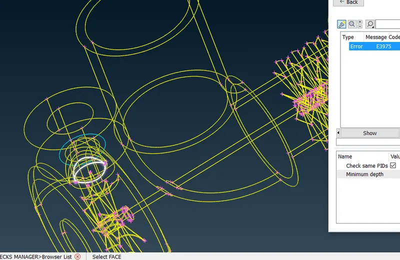
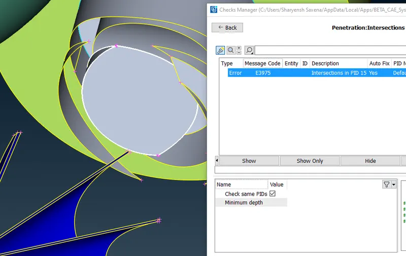
28.we have to delete the below surface after deleting this surface all intersection error are gone
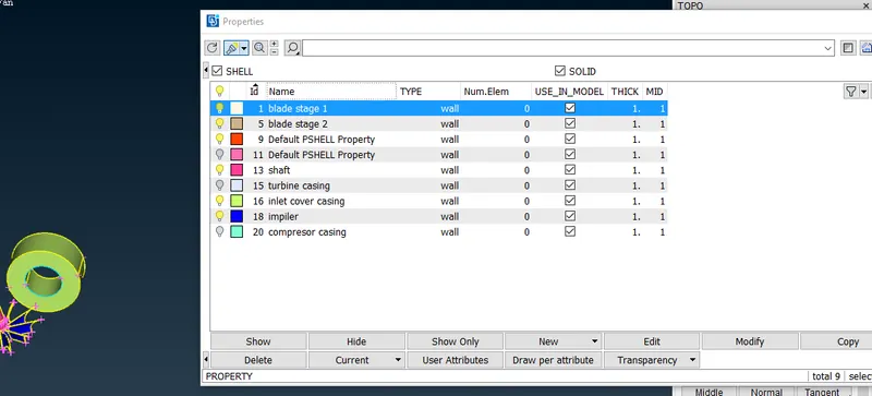
29.now we have to asign all pid names
30.after asigning names we have to close all the surface
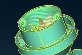
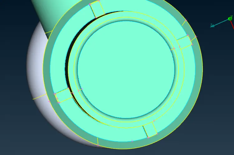
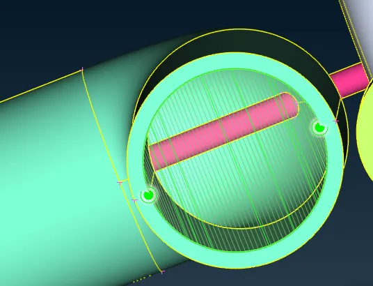
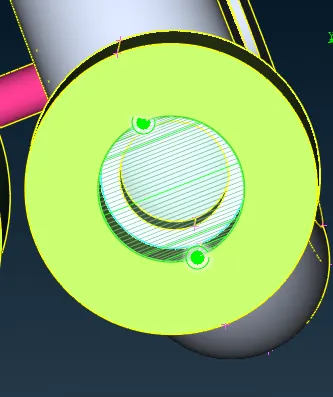
31. after closing all surface there are open surface also in sides of casingso we have to close then also by selecting new cons + loop option and then midle click
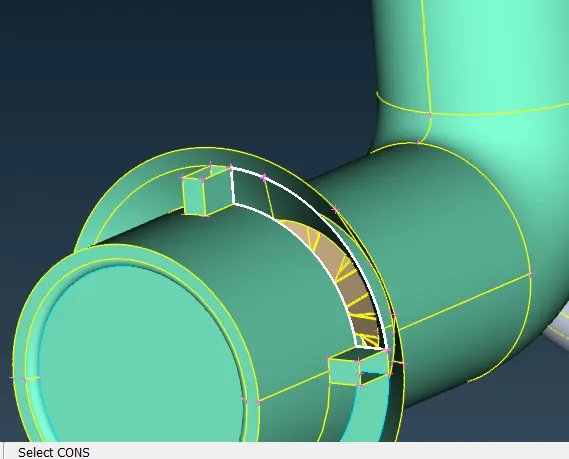
32.32.after closeing all the surface and clering all geomatry error and intersection error we can do surface mesh selecting
so for blade stage 1 blade stage 2 and shaft the target lenght is 1mm so we can take then together first we have to auto cfd in peremeters and then give min length.8 and max length 1.2 and after that cfd visible and select frezze macros
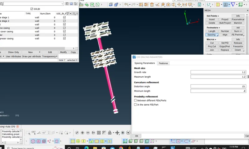
33. now fpr impelor target length is 2mm auto cfd in peremeters and then give min length1.8 and max length 2.2 and after that cfd visible and select frezze macros
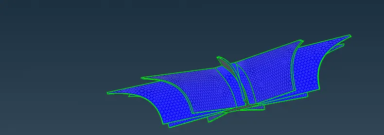
34.for turbine casing,inner cover casing , and turbine casing the target length is 5mm so we can take them together anf for meshing auto cfd in peremeters and then give min length4.5 and max length 5.5 and after that cfd visible and select frezze macros
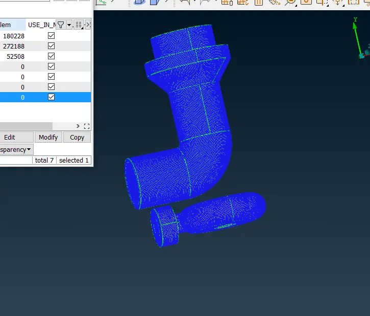
35. after meshing all the parts the mdel will look like as in below and there is not any unmesh parts
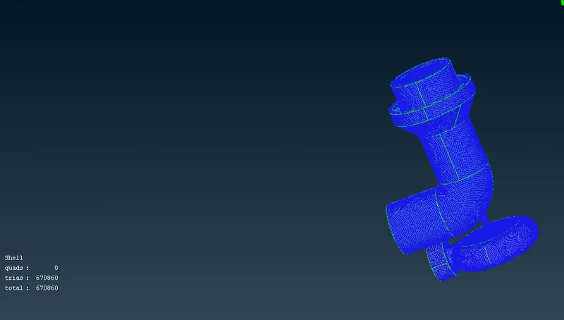
36. after surface meshing done and no unmesh surface are left we can do volumatric mesh by suelecting volumatric mesh and define them . by selecting defne option options are shown as shown in fig and delete the outer surface that is unwanted and then type define and select hole body and then select type of mesh that is cfd mesh and then right click on unmesh and do mesh
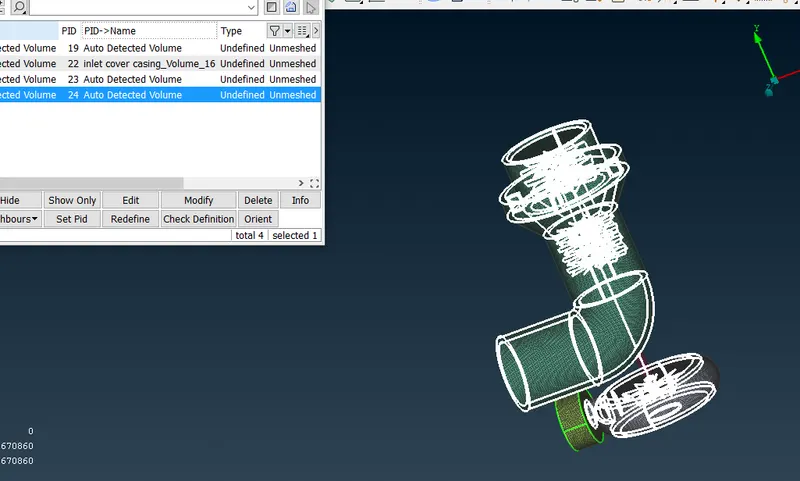
37. now the final model is ready with surface mesh and volumatric mesh with no single cons erroe and no intersection error