Week 4 Challenge : CFD Meshing for BMW car
AIM: To performe the surface mesh for the given BMW car model and also for the fluid domain enclosure which is used for cfd analysis
OBJECTIVE:
- To check for any geometry error in the half potion of the given BMW car model (since the given car model is symetric about z-axis half potion of the given car model is deleted and thus after performing surface mesh for the remaning half it can be transformed to a complete one 0 and to do the respective topological clean up
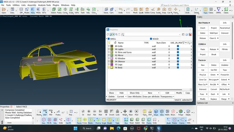
- To assign PIDs ( property identification ) for diffrent part of the given BMW car model
- To performe surface meshing with diffrent target length and qality critiries for diffrent PIDs as follows
- Body -3mm
- Lights -4mm
- Grills -1mm
- Rims and tyres -2mm
- Mirror -2mm
- Window -2mm
- Silencer -3mm
- logo -1mm
PROCEDURE :
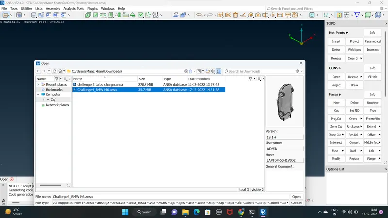
- open the given BMW car model using MENUBAR>FILE>OPEN
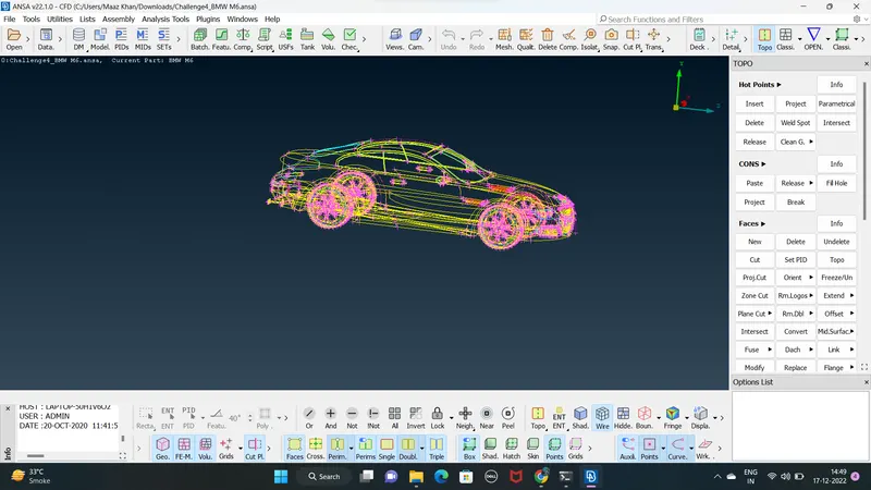
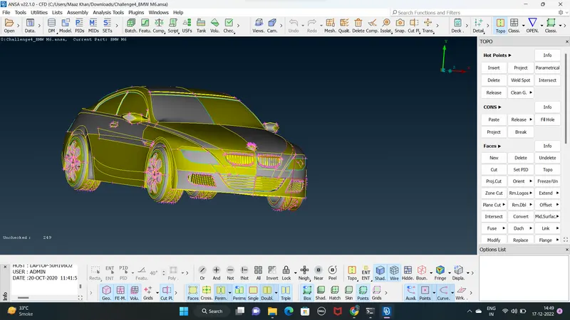
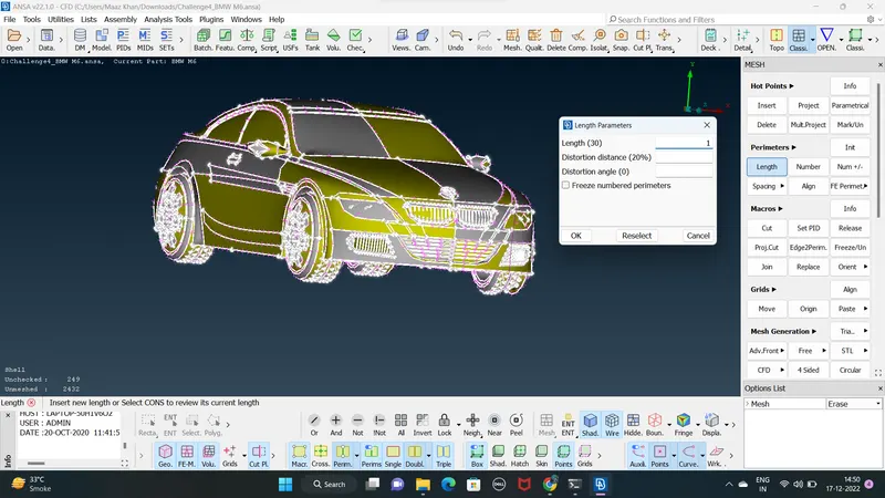
2. since the given car model has the coarse geometry the geometry has been made smooth which is done by defining the mesh length for entire perimeter for the given car model as 1mm by using MESH>PERIMETERS>LENGTH
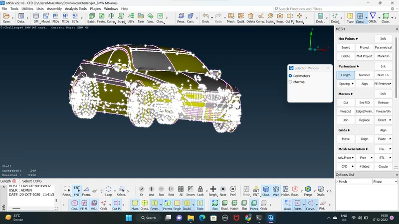
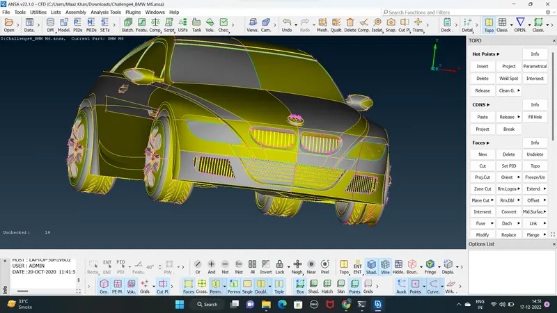
3. since the given car model is symmetric about z-axis delet half potion of the car except the BMW logo region using MENUBAR>UTILITIES>DELETE
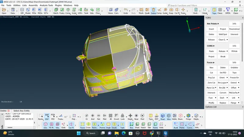
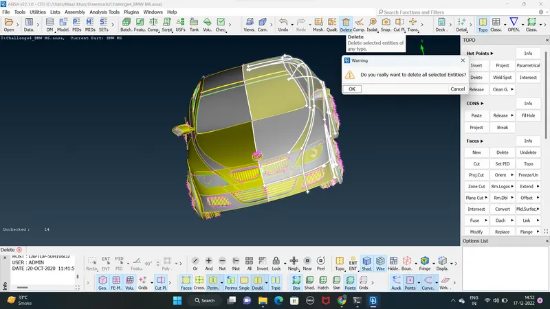
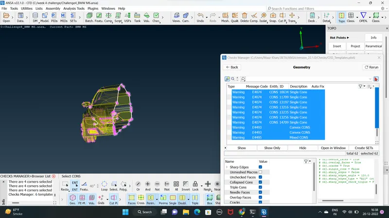
4. Now check for the geometric errors in the remaning regions using MENUBAR>TOOLS>CHECKS>CHECKS MANAGER
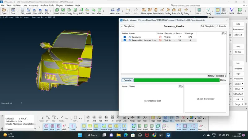
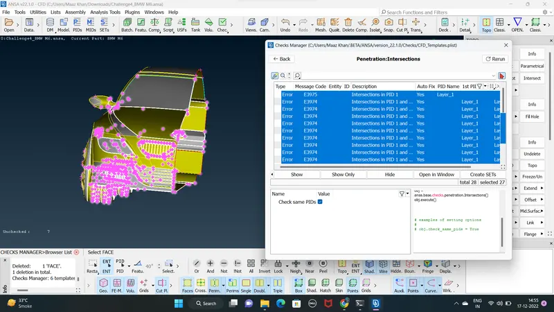
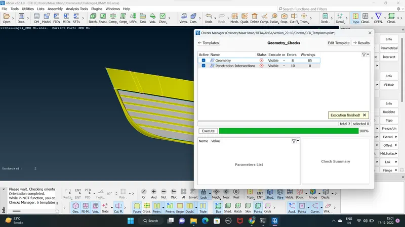
5. given car model has more geometrical error so isolate region individually and performe the topological clean up first isolate the front grill using MENUBAR>FOCUS>iNOT and click for geometric error it using MENUBAR>TOOLS>CHECKS>CHECKS MANAGER
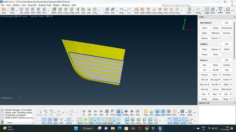
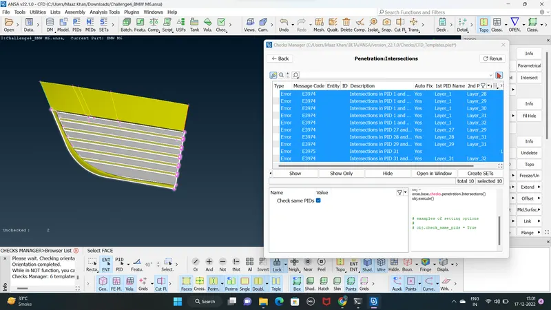
6. deleting all the overlaping surface that form the triple cons and the unwanted surface the internal cae surface can be dekleted since the fluid domain is over the external surface also the internal car volume should be one ( single ) volume
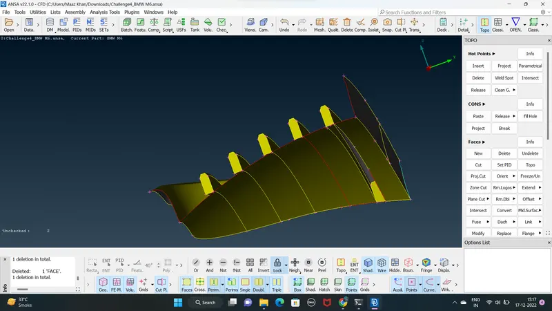
7. using the project option to project the cons down face and delet that over lapping faces and create new face using TOPO>FACES>NEW>CONS
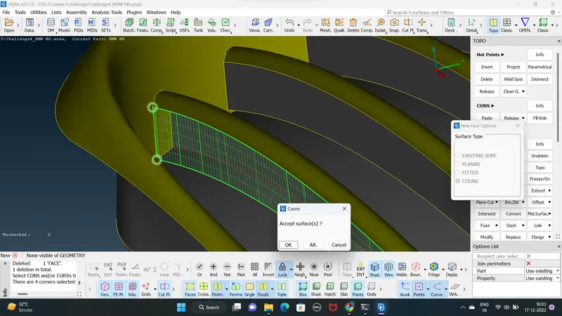
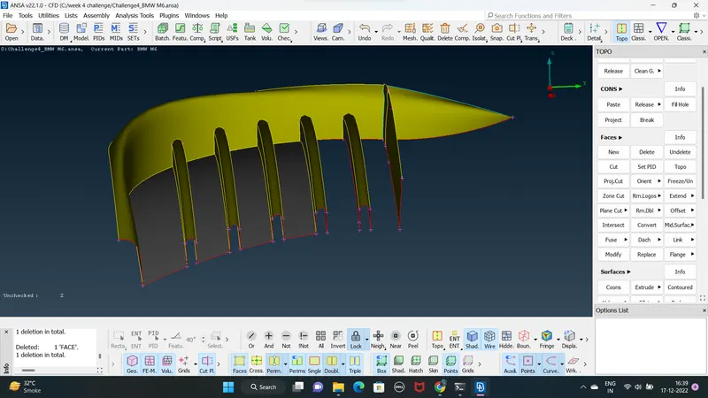
8.after performing topological clean up for the grill for any geometric error using MENUBAR>TOOLS>CHECKS>CHECKS MANAGER
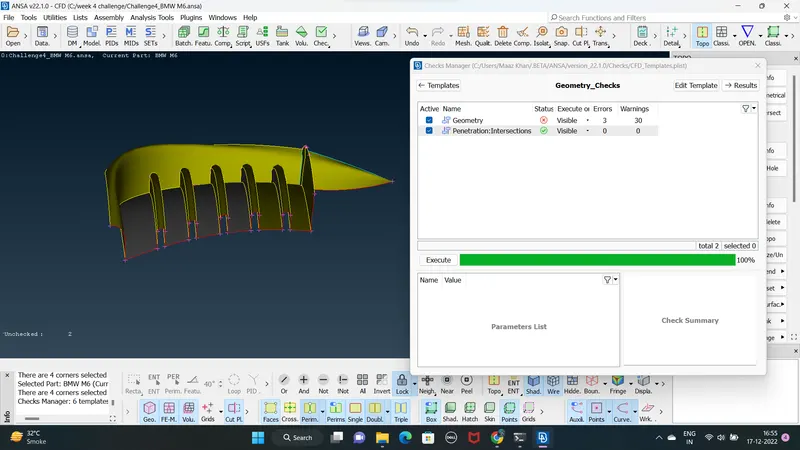
9. next isolate the 2nd grill region and check for any geometrical errors
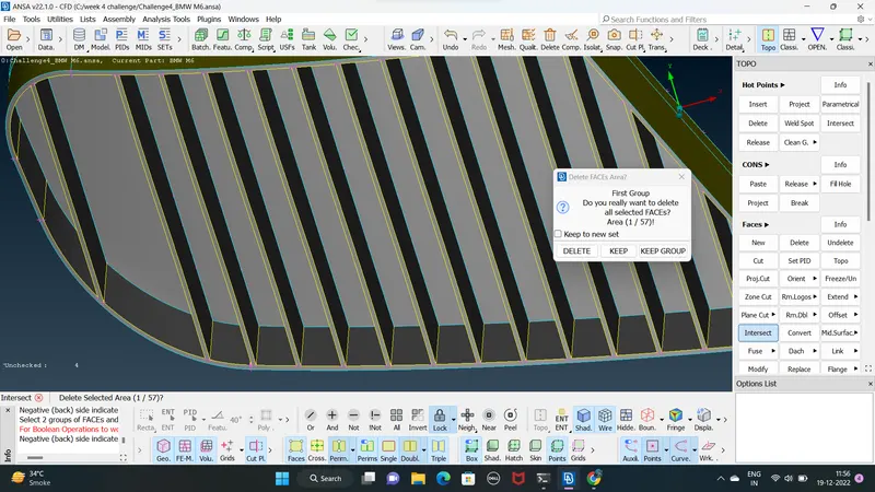
deleting all the overlapping unchecked and unwanted internal surfaces using MENUBAR>UTILITIES>DELETE
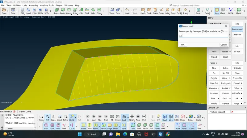
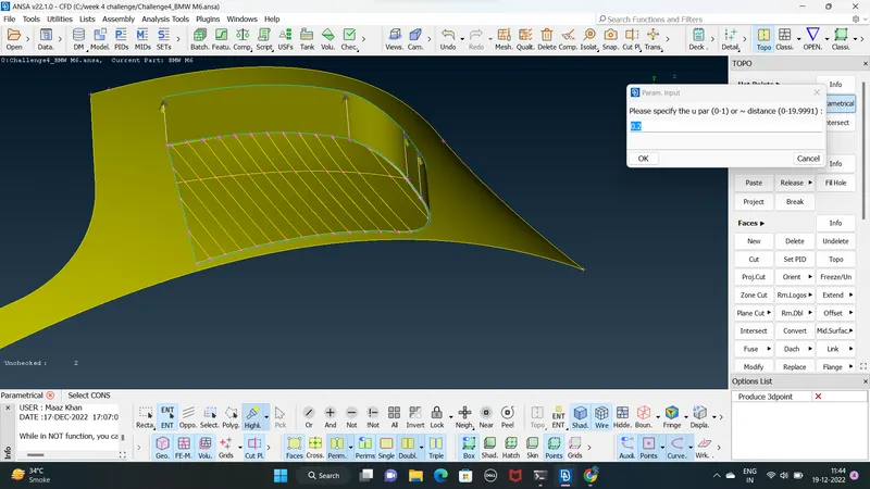
the grill faces delet before using parametrical distance at the face the distance is 0.2 as show in fig
TOPO>HOTS POINTS > PARAMETRICAL creating dis hot points as .02
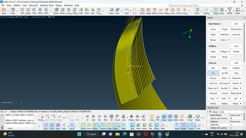
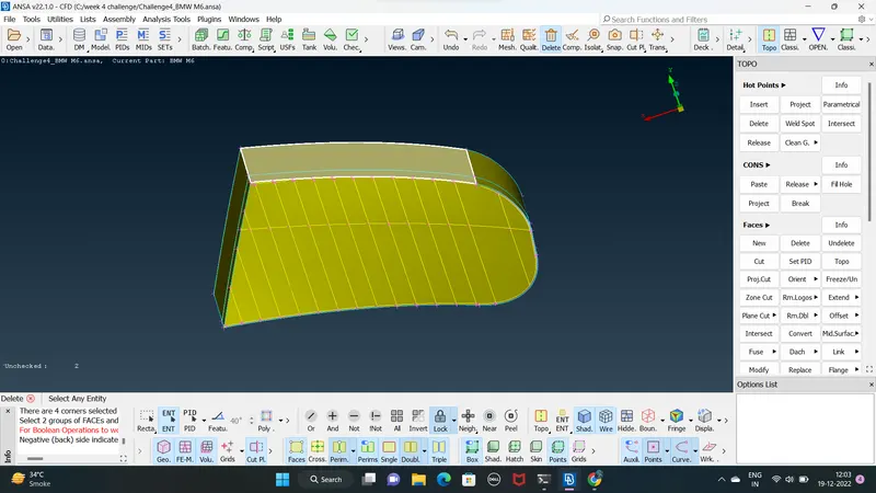
10. using cut option to cut the faces have creating hot points at using a parametrical dis 0.2 using TOPO>FACES>CUT
after cut the faces creating a face using TOPO>FACE>NEW>CONS as show in below fig
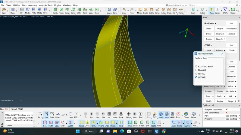
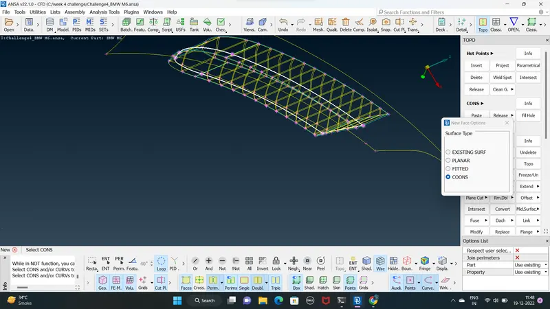
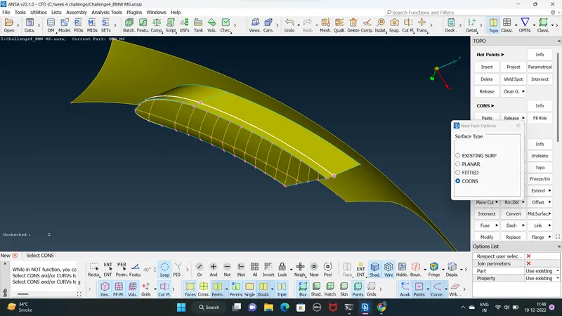
11. creating a face after using intersect option to delet the unwanted faces using TOPO>FACES>INTERSECT
1 face as creating a new face then 2nd faces is full PID PART ( FULL FACE )
and delet the unwanted faces manually using TOPO>FACES>DELET
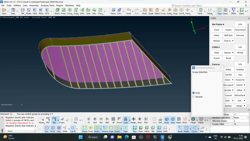
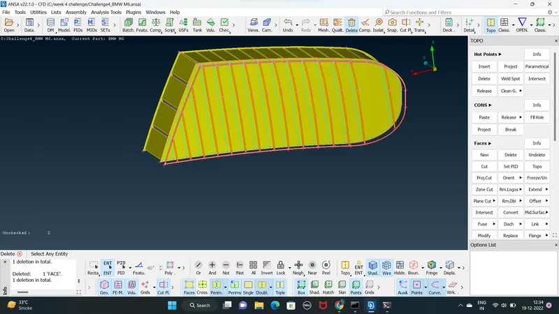
12. clearing all geometrical error recheck again using MENUBAR>TOOLS>CHECKS>CHECKS MANAGER
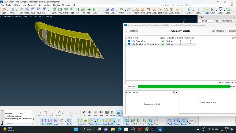
13. lets delet the front light inorder to performe topo clean up in it deleting unwanted faces
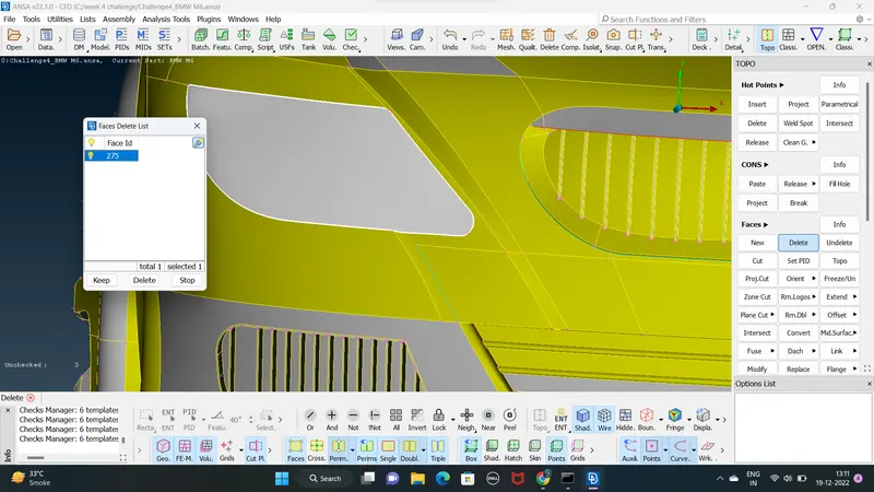
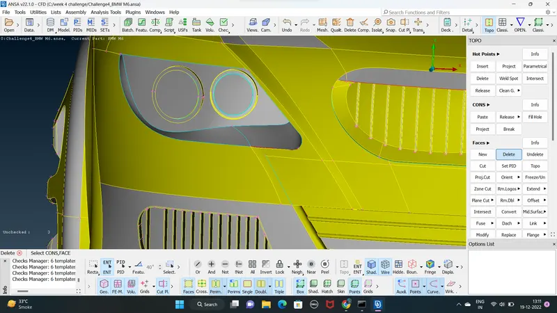
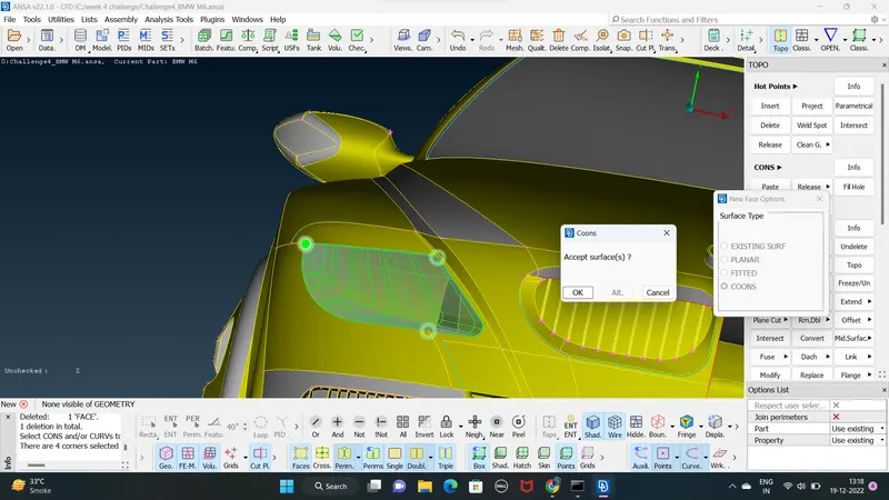
14. delete all the unnessecary and unwanted faces then create a new face using TOPO>FACES>NEW>CONS
15. next isolate the middle grill part
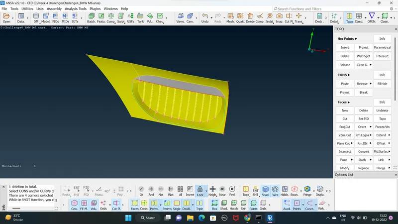
16. lets delet the unwanted faces and creating and filling the areas of the middle grill 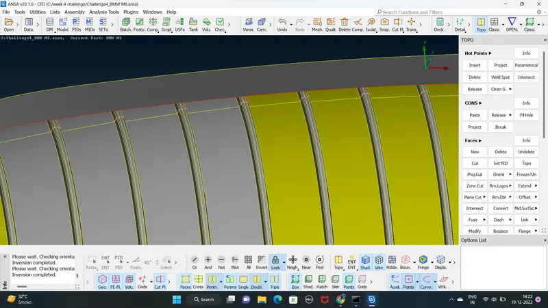
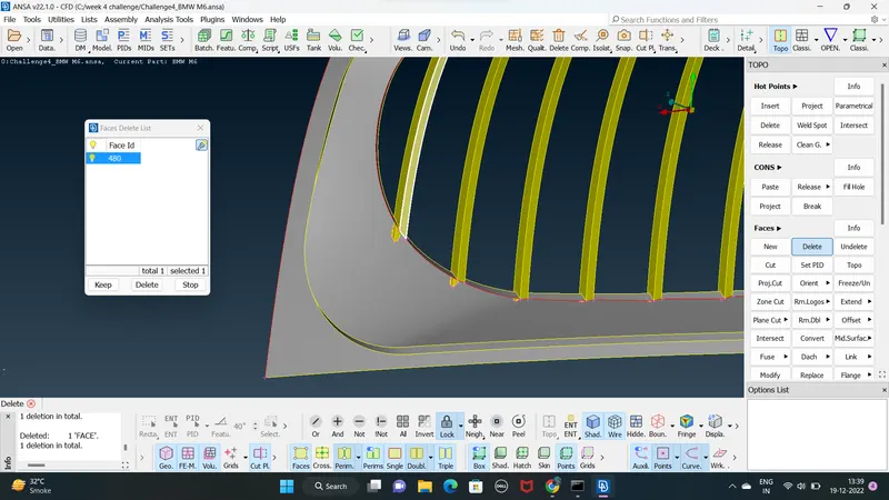
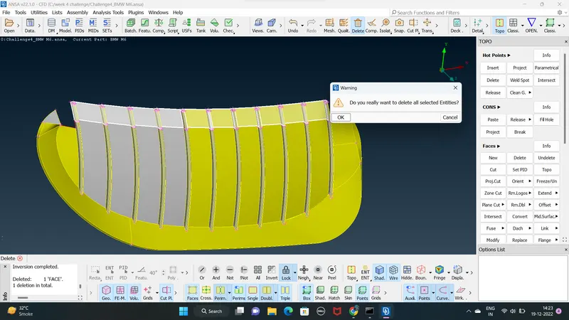
17. creating some hots points and make new face show in below fig TOPO>HOT POINTS>INSETS
face TOPO>FACES>NEW>CONS
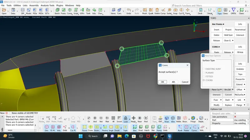
18. some faces filling using fill hole option
TOPO>CONS>FILL-HOLE
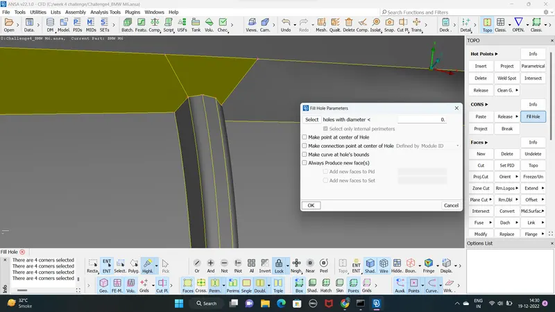
19. clearing all the geometrical errors checks using MENUBAR>TOOLS>CHECKS>CHECKS MANAGER
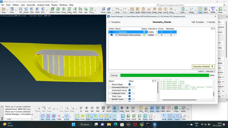
20.the logo of the car is isolated and the triple cons are eliminated by deleting the isolated surface this create a gap on the outer surface of the logo which is create using TOPO>FACES>NEW>CONS
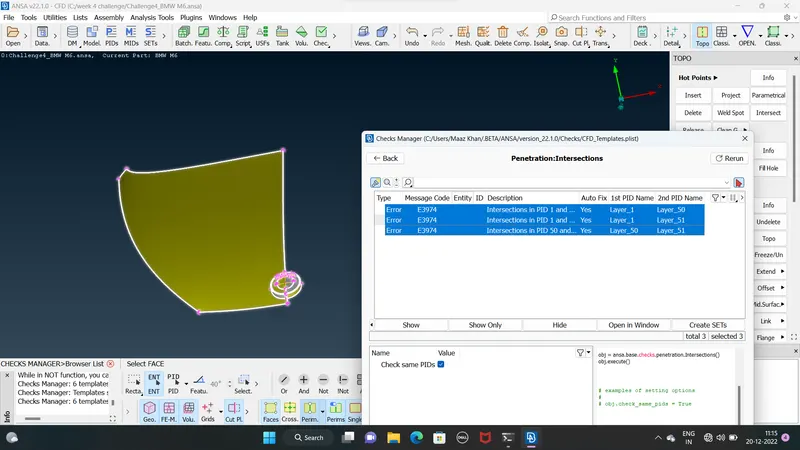
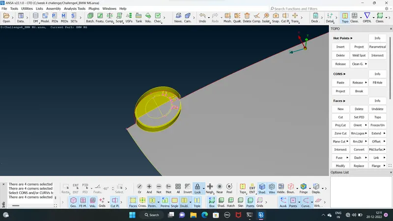
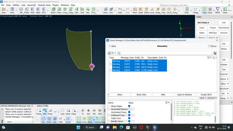
21. the single cons having no connections to the surface are extend to ajdusted surface from a complete surface to faciiliture easier deleting to surface the single cons avilable are made
lets isolate the single cons showing that face
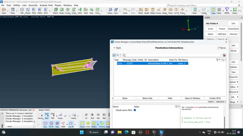
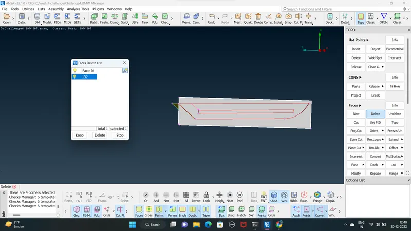
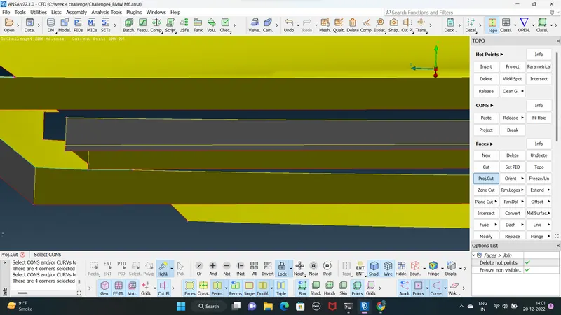
22. the inner side has a surface which is not isolated to isolate this first use extend option TOPO>FACES>EXTEND
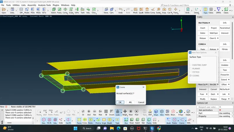
extend the single cons on the required surface new create a new faces using cons option and isolate the required surface and delet it extra unwanted faces
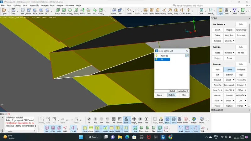
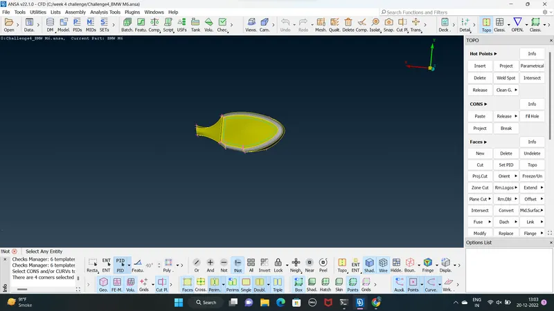
23. the mirror is isolate using iNOT option and the outer surface of mirror are hidden to
easy deleting the overlapping surfaces present in the inner side mirror
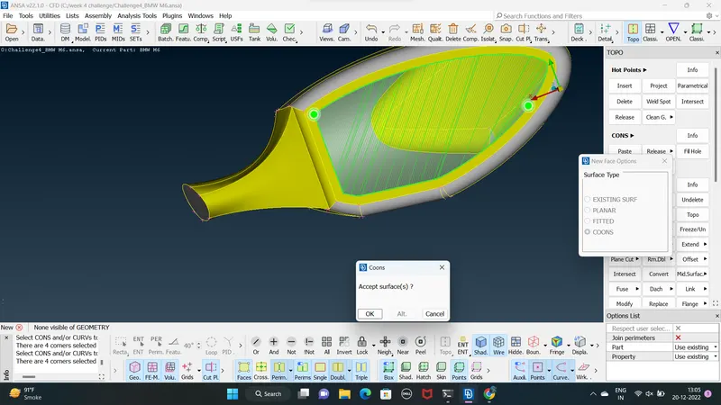
24. since the mirror will also from seprate volume deleted the circular surface and extend it to the surface of the window sheild to form an overlapping surface delet the overlapping surfaces to include mirror as a single volume with the car
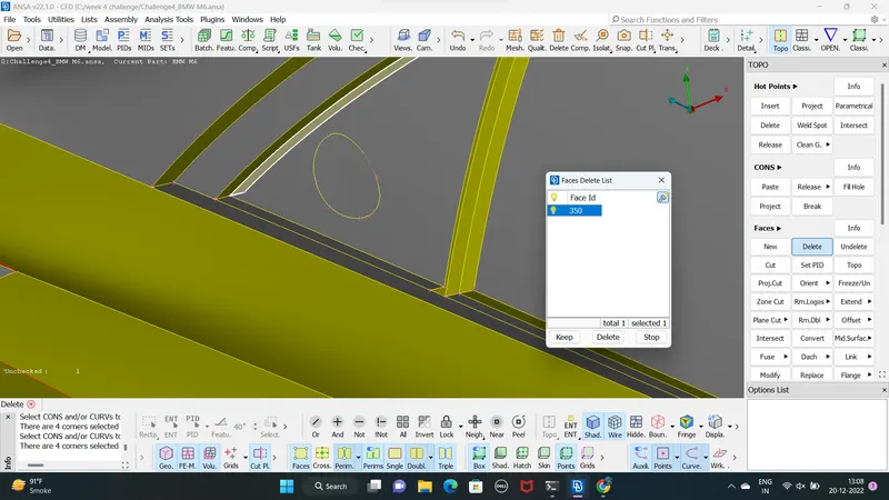
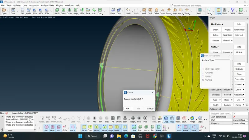
25. the tyre is isolate the car body using iNOT option enable pid region mode the view is loocked and the top surface of tyre is hidden using NOT option MODMENU>TOOLS>BOOTOM iNOT>NOT and lock it
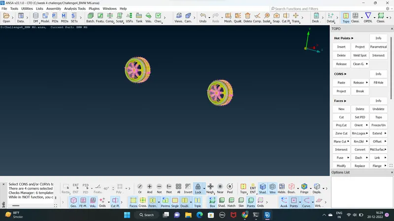
26. the overlapping surface are deleted using delet option To resolve the single cons the surface adjust to them are deleted and new slant surface is creating using cons option deleting triple cons
TOPO>FACES>NEW>CONS
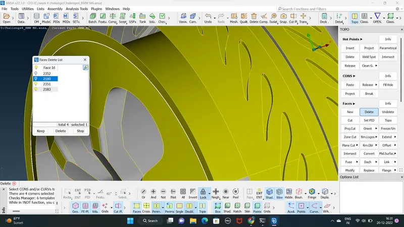
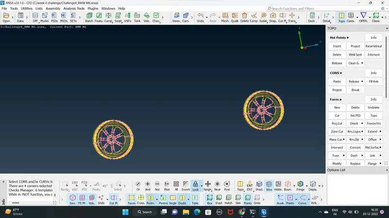
27. repeat same procedure for the other tyre
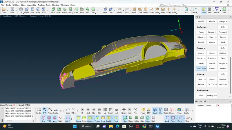
28. The rear part (BOTTOM) of the car having duplicate surfaces are deleting using TOPO>FACES>DELET
Before deleting the base surface of the car is deleted use CONS2CURVES option in curve menu TOPO>CURVE>CONS2CURVE
selet the single cons and middle click enable the curve option at the bottom of the interface and delet the axcess curves
29. deleting unwanteed faces and creating new faces
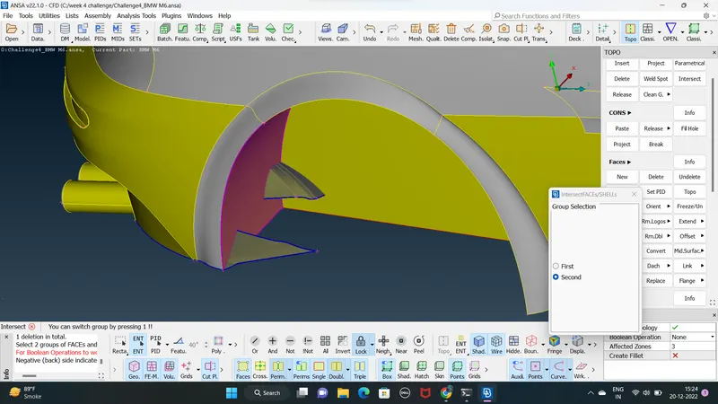
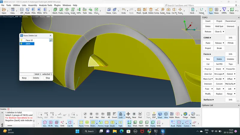
30. after clearing all the topological geometrical errors lest check the model only single cons are found cut of the half part
31. lets assigned the PIDs for every region of the given car model using MENUBAR>LISTS>PROPERTIES
and The additional PIDs are deleting using conmpress option MODEMENU>UTILITIES>COMPRESS
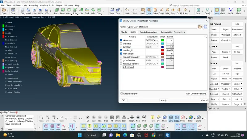
32. select the open form deck and under topo mode click quality criteria and enter the quality criteria for the meshing
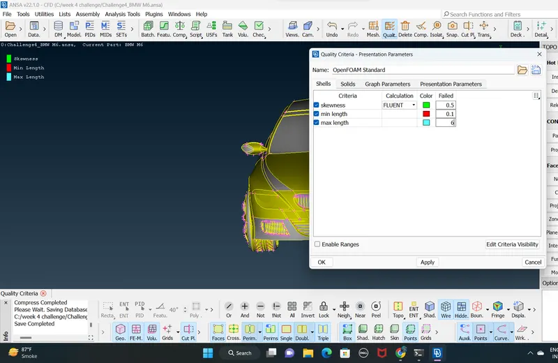
33. GIVING maximum length 6
minimum length 0.1
SURFACE MESHING :
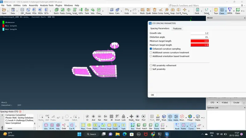
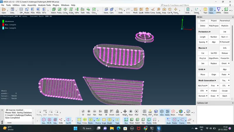
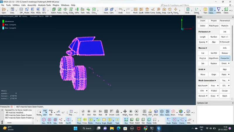
1. LOGO & Grills TARGET LENGTH 1mm
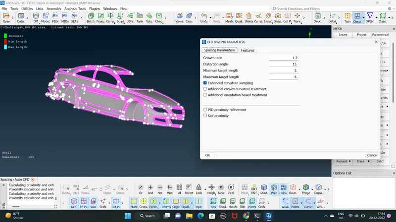
using parameter spacing auto CFD target length
minimum = 0.8
max 1.3
perform surface meshing than freeze the meshing parts using CLASSIC MESH > MACROSE >FREEZE&UNFREEZE
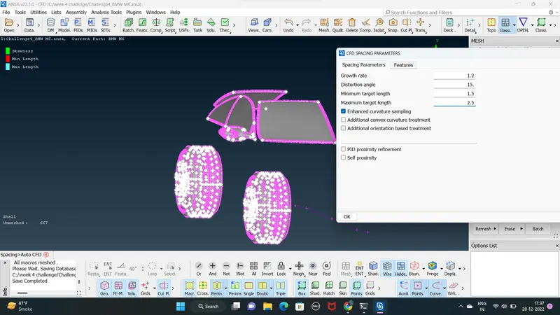
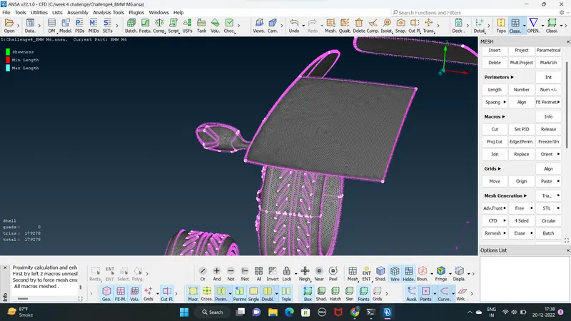
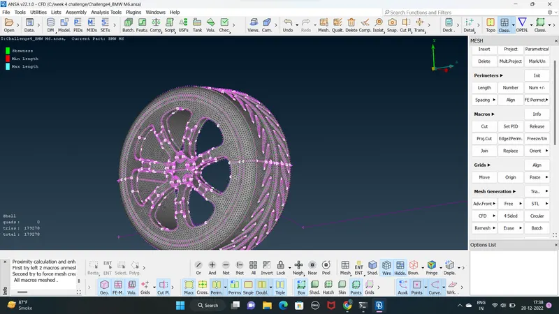
2. Rims & tyres , mirror and Window
TARGET LENGTH 2mm
Minimum = 1.5
maximum =2.5
3. Body & Silencer
TARGET LENGTH 3mm
minimum =2
maximum=4
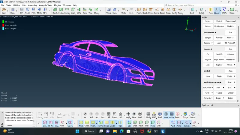
34. completing surface mesh lets unfreeze the part
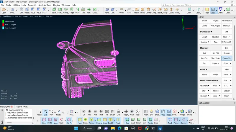
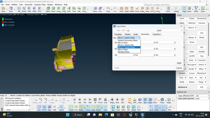
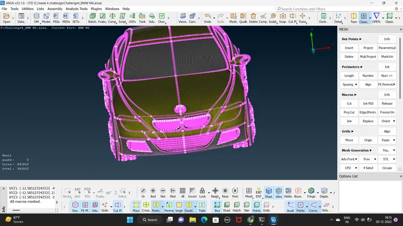
35. the next step is to assign symmetry option to the mesh model
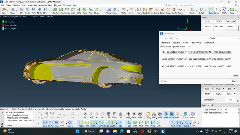
click the transforme and select copy option under entities select the entire geometry that is to be mirrored and deselect the logo
CREATING AND MESHING OF WIND TUNNEL :
- wind tunnel is a medium where the wind flow over the car be analysed in cfd application
- The wind tunnel is designed with respect to the dimonsion of the model if the model has x mm length then the front face of tunnel must be at 4x mm distance the rear face must be at 6xmm below the model with a considrable gap and the rop view the side faces of the tunnel must be x mm on either side
- select relative option in points menu and select a point at ther base in y axis set at aribitary distance at -200
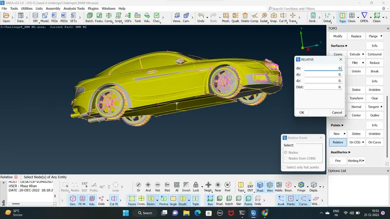
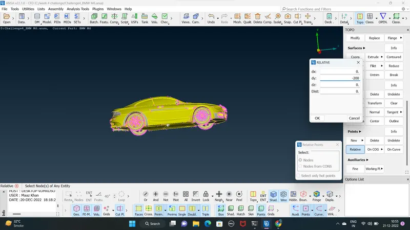
- measure the distance between the create points and the model at the front part of car add the distance is 660 mm with the 4x mm distance 5850 to obtained the front face end of the tunnel
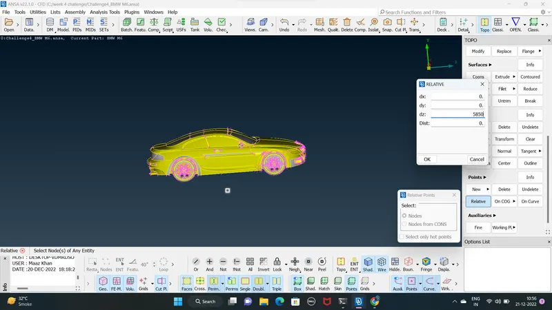
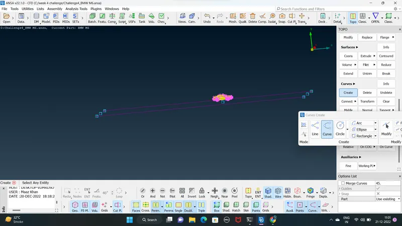
- the points are then converted to curve using create option in curves menu ans selecting the end points to from a enclosed surface the surface is then creating using cons and assigned a PIDs under PID manager
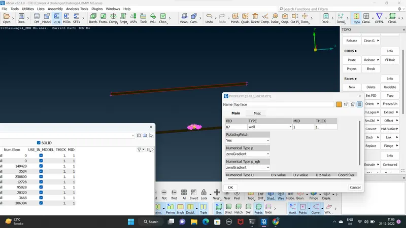
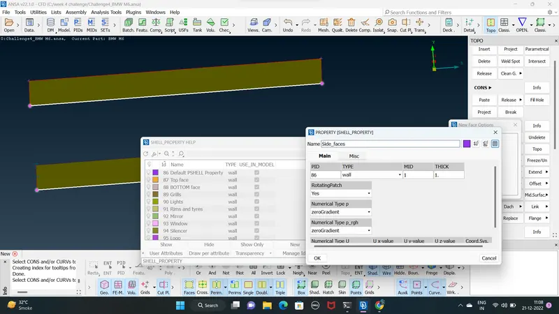
- the top surface is creating using the base surface as a refrance the vertcal distance between the bottom points and the car top surface is mershured 410 mm and its added to a 3xmm distance
- click the offset option in faces menu select refrence surface and ender the offset distrance -4420
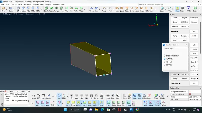
- create the remaning surface of tunnel using corns option also assigne the respective PIDs to site surface IN PIDs MANAGER
surface meshing
BOTTOM PART
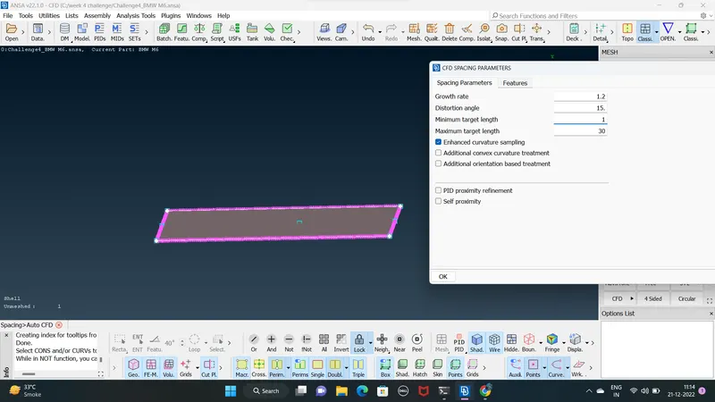
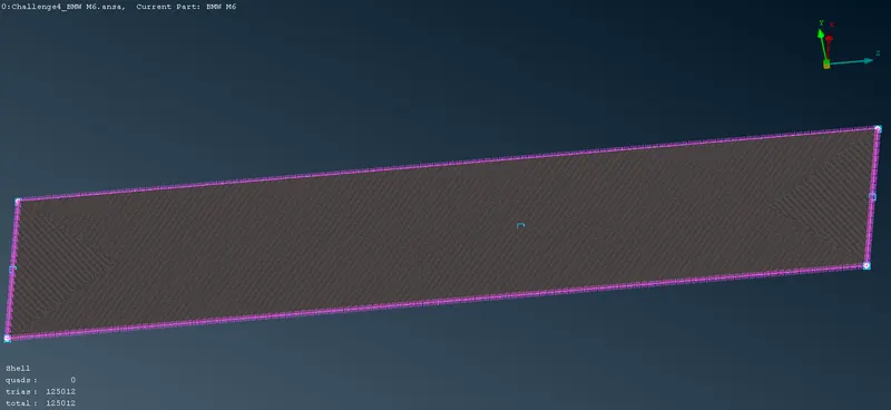
TOP FACE
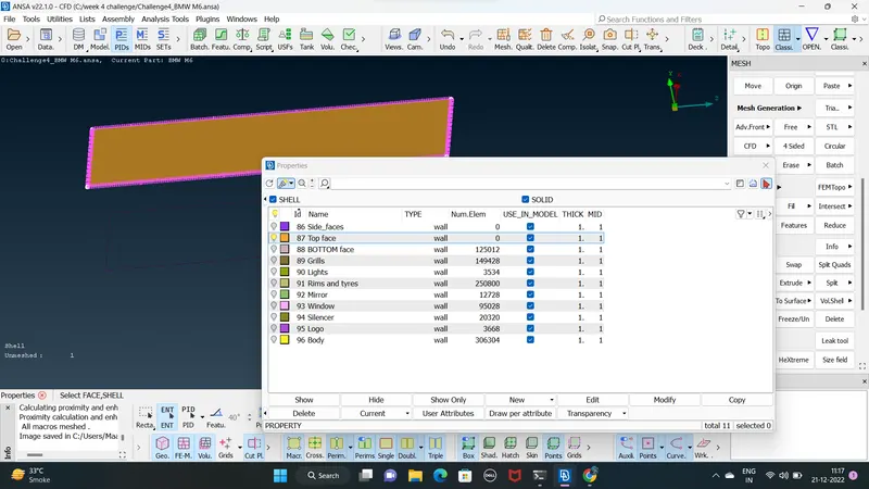
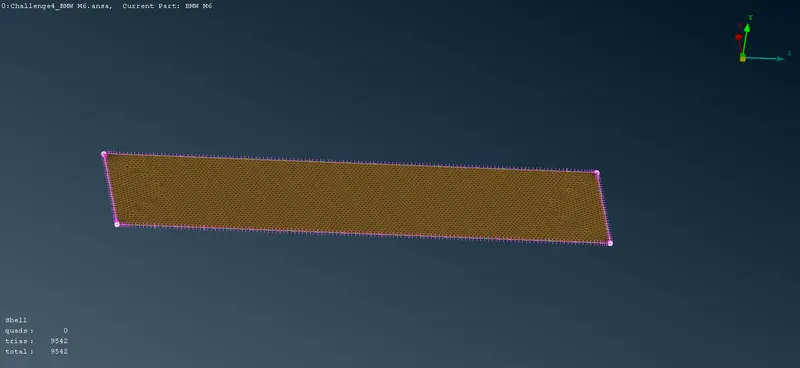
SITE FACES
- using spacing maunul meshing
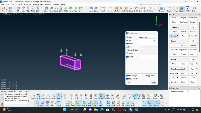
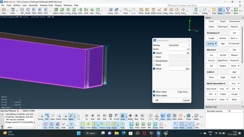
- the meshing along the height of the tunnel is be varird from 20mm to 200mm spacing option in programming and select biasing grometry
- the botton face is aasign the isolate the meshing by asigned minimum and maximum length 20mm and 200mm the front rear and the side surfaces are meshed one surface at the time
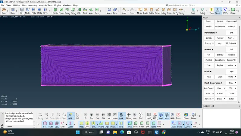
WIND TUNNEL MESHING
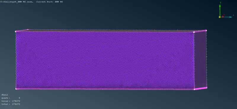
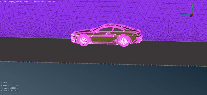
RESULT
- the topo cleanup and the surface meshing with diffrent mesh length are required by the PIDs is performed
https://drive.google.com/file/d/14dy6-8nG-PLs3WMpmES2lOcZSiOVH2N7/view?usp=share_link