Week 2 Challenge : Surface meshing on a Pressure valve
AIM : surface meshing on a pressure valve
objectives :
- To check for the geometrical errors.
- To perform Topology Cleanup and PID allocation
- to set three diffrent target lengths as three different cases and mesh the model.
- to do cases of 3 different models with target length 1MM , 3MM , 5MM .
- and performe 1mm target length with volumetric mesh
- to mentain case that is giving good result with reason.
PROCEDURE :
- initially we downlode the model and import it into the ANSA softwarw opening
- the ANSA file . This model has some Topological errors which we have to solve
1. TOPO-CLEANUP:
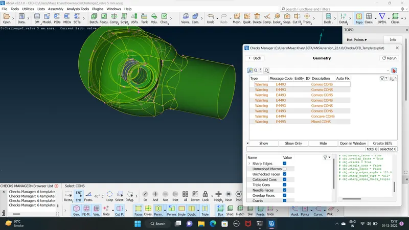
- The first thing to do is to check the single cons and triple cons in the model
- single cons are cons that are shared with only one surface ( meaning as open surface for closed geometry
- triple cons are created due to the con shared with the three surfaces and also need to be resolved based on the weather that is desired or not at that location
- triple cons are not always erroes ( faults ) but it does show that local volume can form because of three faces
- The single cons and triple cons are identified using geometric checks ( checks Maneger )
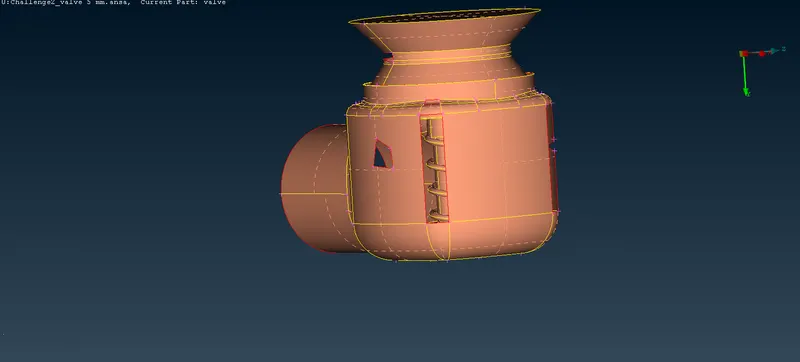
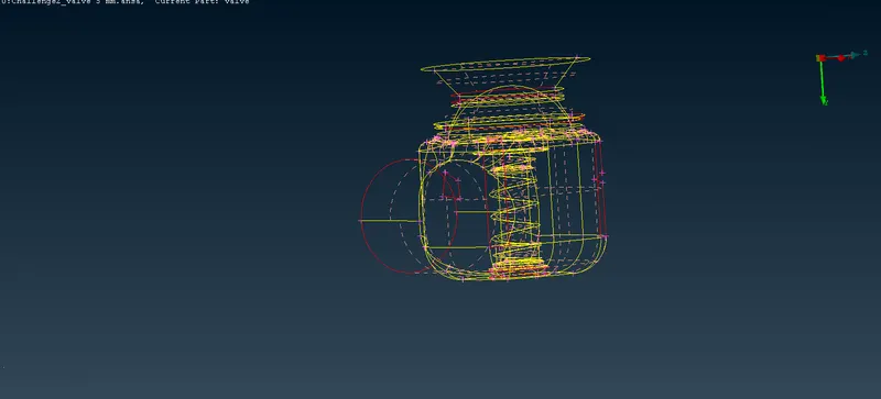
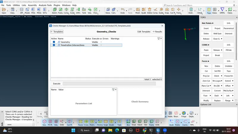
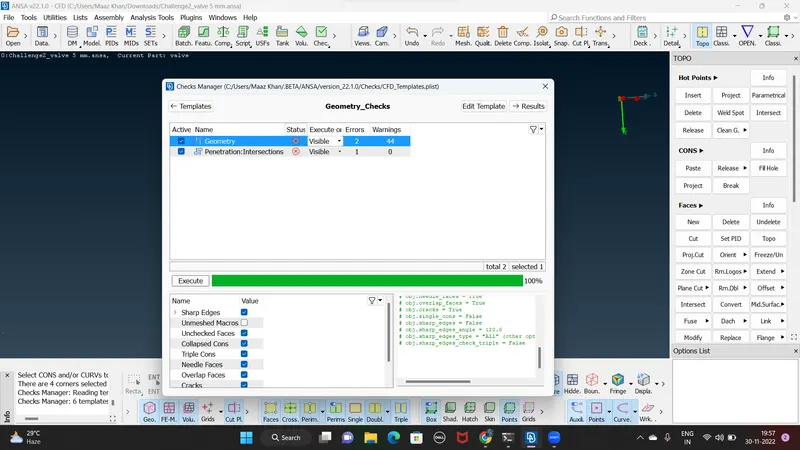
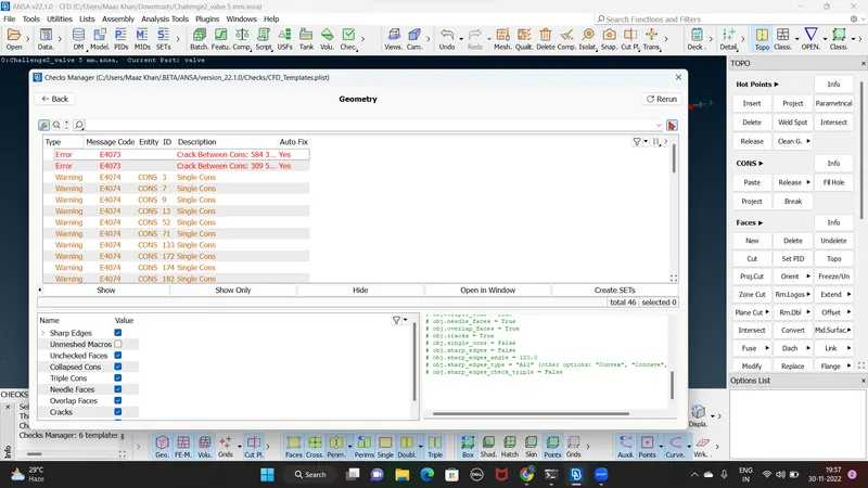
- It can can also be seen by disabling the double cons from bottom bar with wire frame mode CANTRL+SHIFT
- we observed various single cons and few triple cons
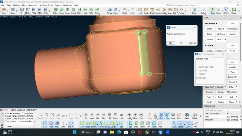
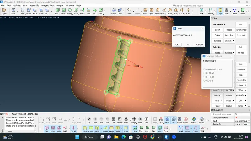
- there are few open surface that are forming single cons and it is filled by creating surfaces in FACES OPTION
- FACES-NEW-CONS/ FITTED / EXISTING SURFACE / PLANAR- suitable option is selected accordingly ans surfaces are filled its create perpendiculae face ( its not suitable for curves faces )
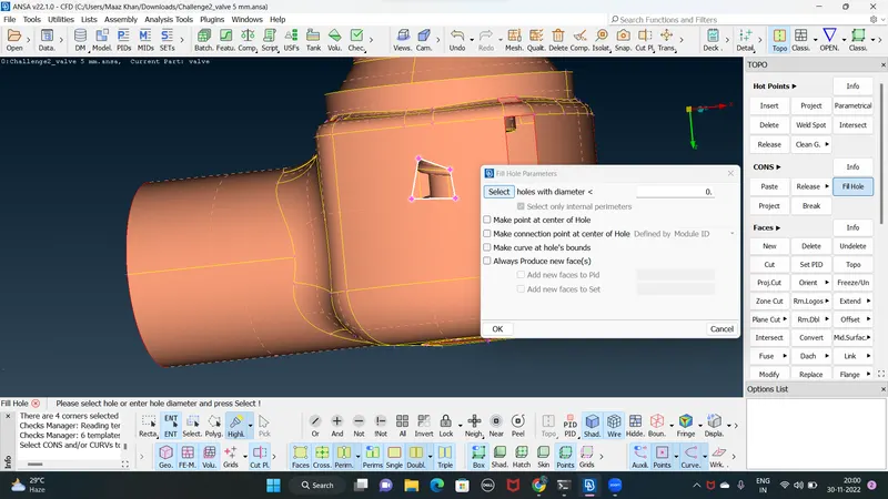
- and one more option its called fill hole show in below image
- In many places one an more of these options may give satisfactory results
- The method is chosen based on the most satisfactoey surface formation for closed areas we can also use fill hole option in the cons selection inside the TOPO Deck
- in complicated geometry shaping in the entire surface may not work properly so the surface must be created in small parts
- The bottom and top side surfaces are closed using the fill hole option or the cons option
- The bottom hole a triple taper is formed after the face is closed and the triple taper is visible there due to the fact that the three faces are touching so its not as an error
- final model after TOPO-CLEANUP will be free from single cons
2. PID ALLOCATION
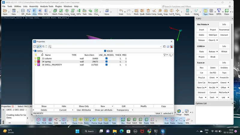
- PID is property ID used to store the spacific information about geometrical entities
- apply boundray condition for cfd application whole geometry is divided into number of PIDs
- TOPO desk FACES- SET PID ( column , spring )
3. MESHING
- after completing the pid allocation we can start our meshing procedure for any mesh initial steps
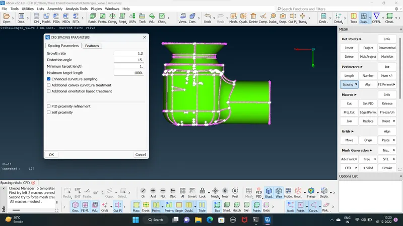
- we first set the mesh length using length option for both perimeter and macrose then we use mesh tab and set the target length maximum and minimum mesh length respectively
- go classic mesh peremeter select SPACING - PEREMETER AND PUT THE MAXIMUM AND MIMUM VALUE OF MESH LENGTH AS SHOW IN THE fig
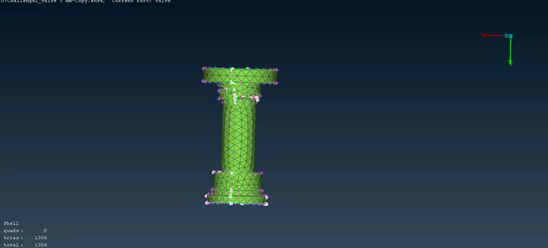
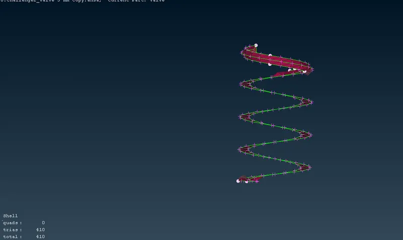
CASE 1 :- Target mesh length = 5MM
minimum parameter = 4.5
maximum parameter = 5.5
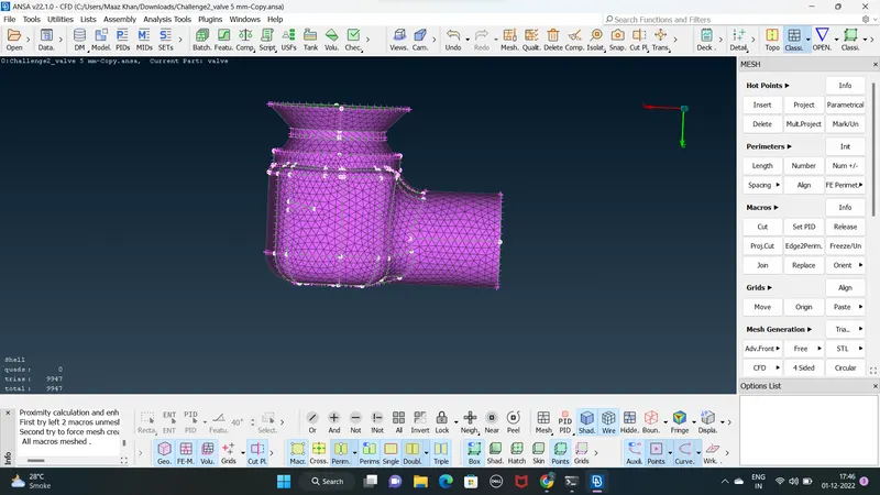
Final Model :
COLUMN :
SPRING :
CASE 2 :- Target mesh length = 3mm
minimum parameter =2.5
maximum parameter = 4
FINAL Model :
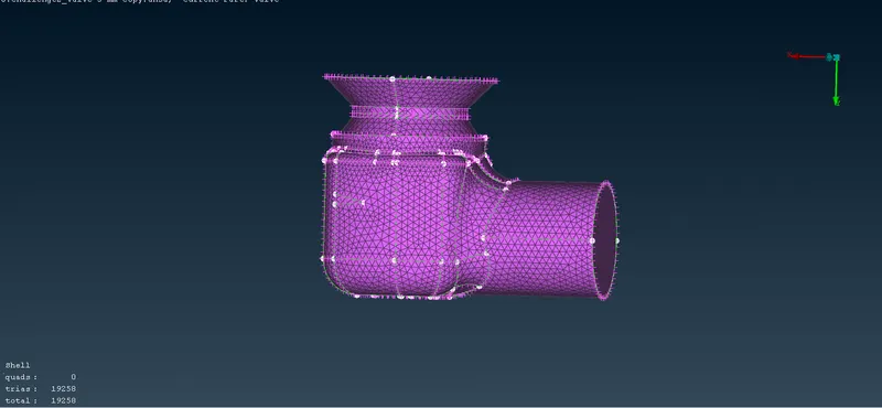
COLUMN :
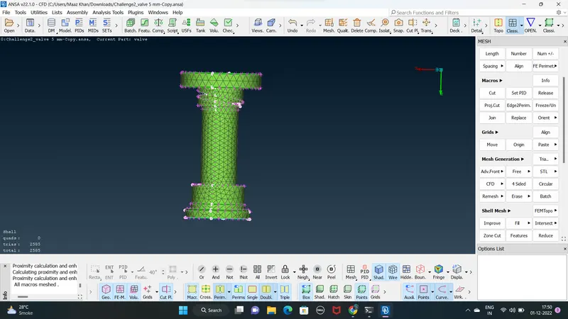
SPRING :
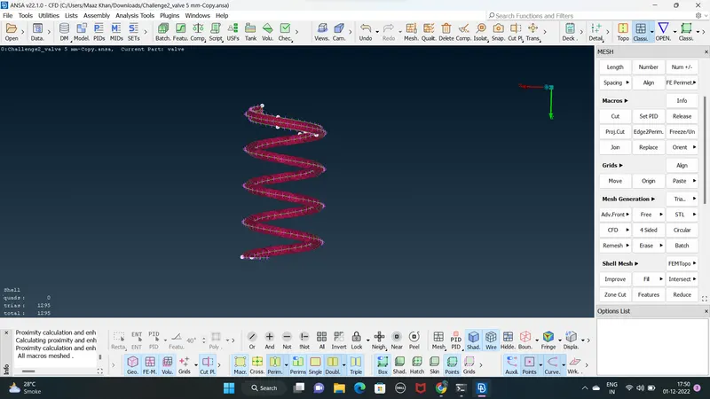
CASE 3 :- Target mesh length = 1MM
minimum parameter = 0.5
maximum parameter = 1.3
FINAL model :
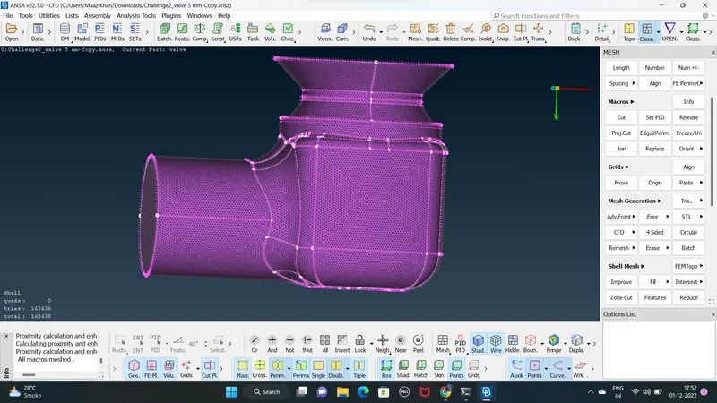
COLUMN :
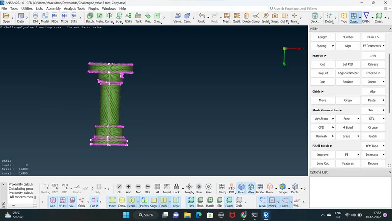
SPRING :
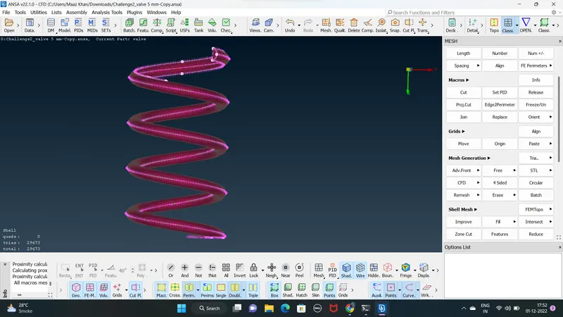
VOLUMETRIC MESH TARGET length 1MM :
click define in volume desk
check the list and delet the un nessesary parts RIGHT CLICK- DELET
click UNDEFINED - TETRA RAPID
then right click remesh
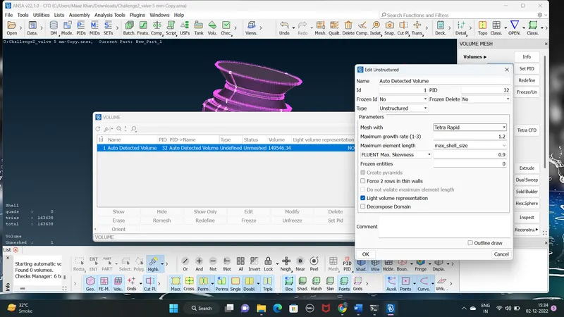
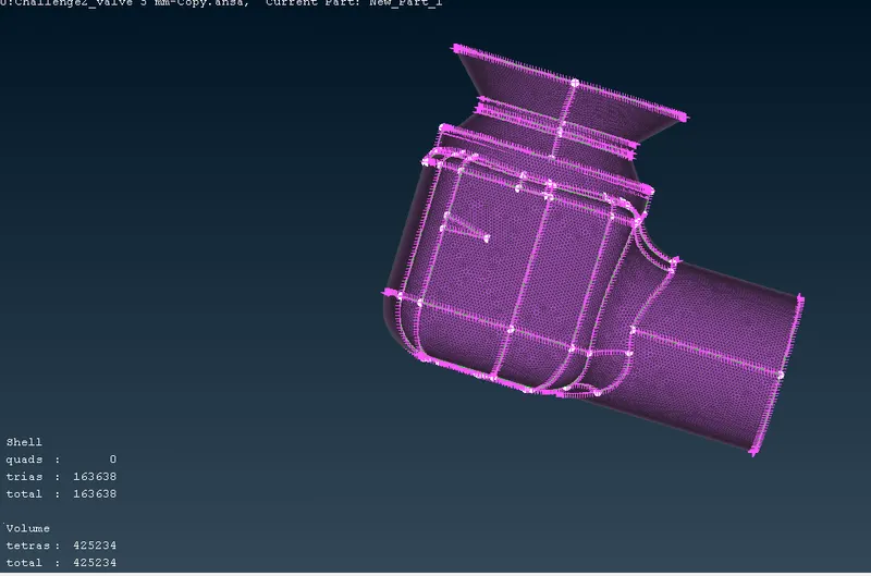
- we have meshed our model with 3 diffrent mesh length and obtained the result the following condition
- as the mesh length decreases the number of elements increases and get more refinef mrsdh model
- mesh length also effect the parts with less surface area (SPRING)
- for mesh length =5mm the mesh quality very low
- for low mesh lengths we get more surface finish as compared to larger mesh length visible in results
CONCLUSION
- thus we have succefully meshed the given model ( pressure valve ) with 3 diffrent mesh length and displayed the result and the volumetric mesh also