Project 1 : CFD Meshing for Tesla Cyber Truck
AIM:-
To performe the surface mesh for the given tesla cyber truck model and also for the fluid domain enclosure which is used for CFD analysis
OBJECTIVE:-
The objective of the project is to do a basic geometric check and to do a surface mesh & volumetric mesh using ANSA on the given model Tesla cyber truck Model
PROCEDURE:-
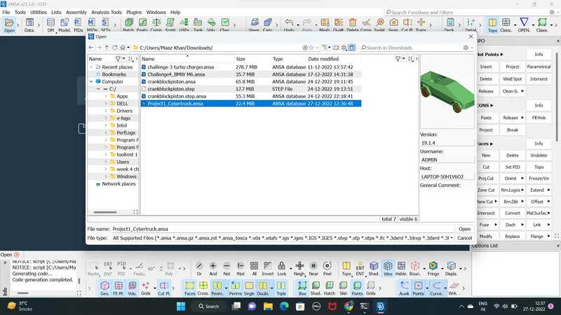
STEP 1 : Open the given cyber truck model using MENUBAR>FILE>OPEN
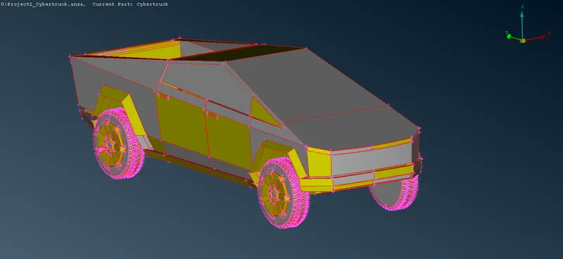
- We can see so many single cons in our model
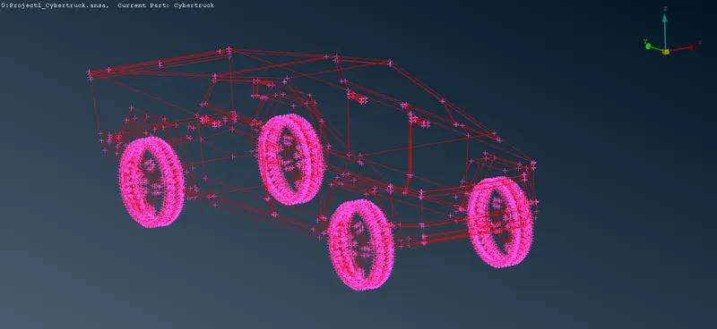
STEP 2: We can just do a TOPO to clean them
TOOL USE :- MENUBAR>TOOLS>TOPO>FACES>TOPO
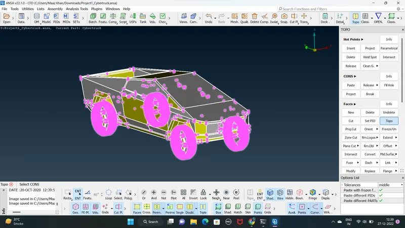
- After topo some of the single cons are changed into double cons
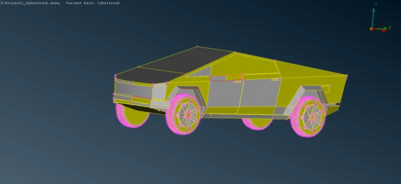
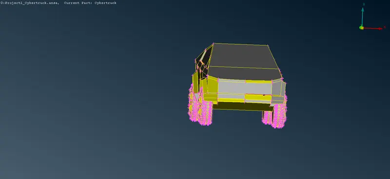
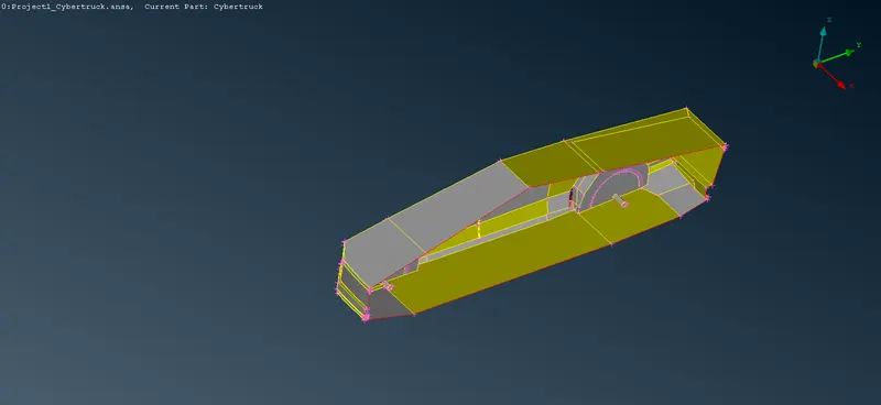
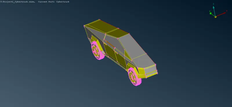
STEP 3: since the given cyber truck model is symmetric about z-axis simple cut the half part of a model using
TOOL USE MENUBAR>TOOLS>TOPO>FACES>PLANE CUT - SINGLE
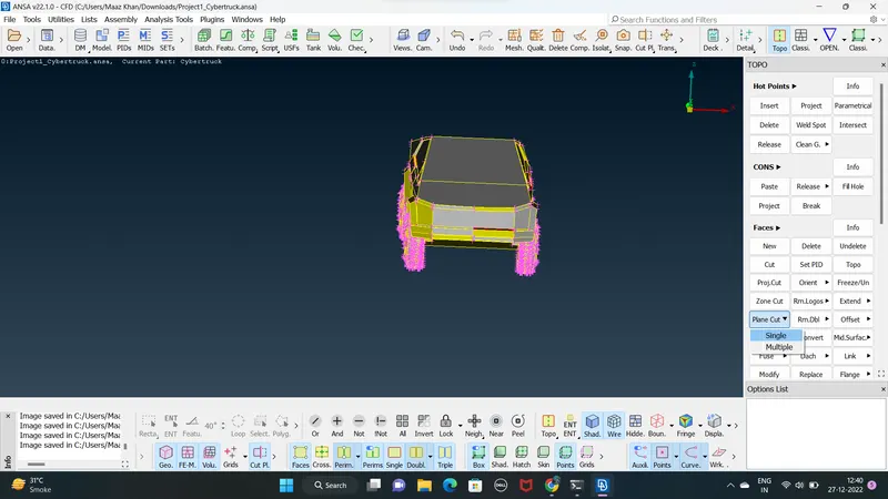
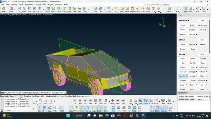
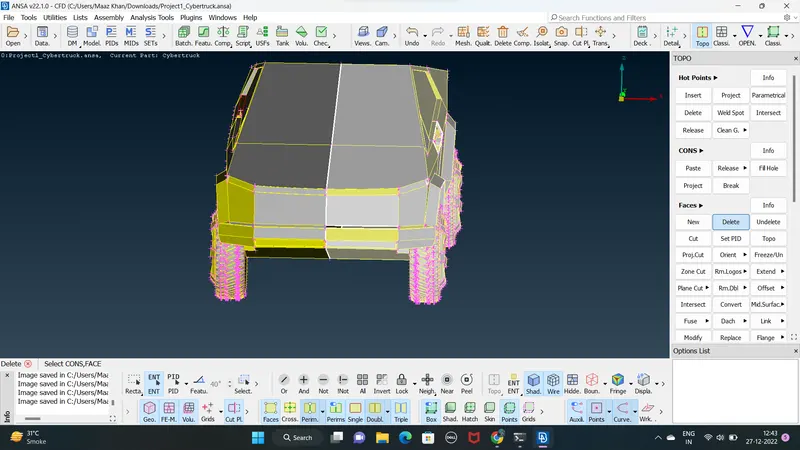
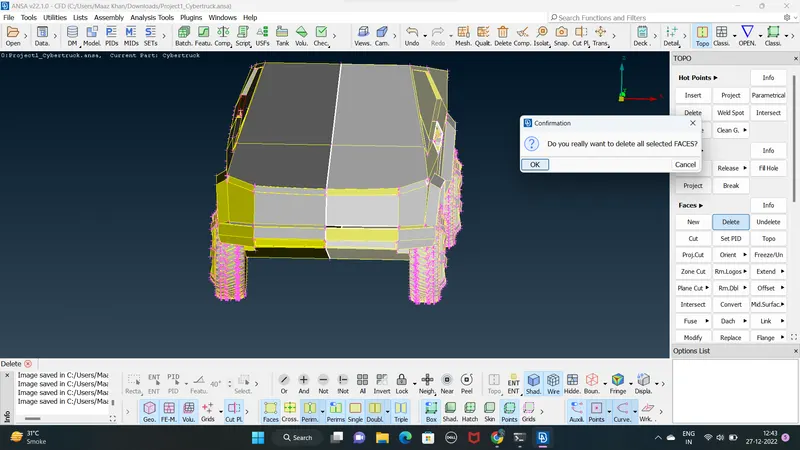
STEP 4 : after using plain cut then selected part delet of a given model using
MENUBAR>TOOLS>TOPO>FACES>DELET `
STEP 5: Now check for the geometric error in the remaning region using
MENUBAR>TOOLS>CHECKS>CHECKS MANAGER
- checks manager : This function open the checks manager it is used to execute a number of checks
- Geometry checks : This function locates geometrical problems of the model such as ( uncheck faces . needle faces . collapsed cons . single cons . triple cons . overlap and cracks )
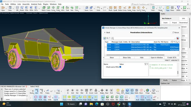
STEP 6: the given model has geometrical error . performe the topological CLEAN-UP first
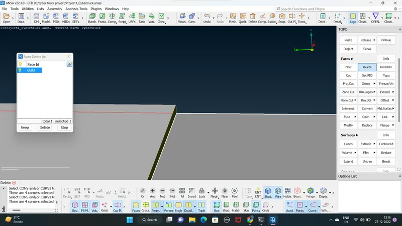
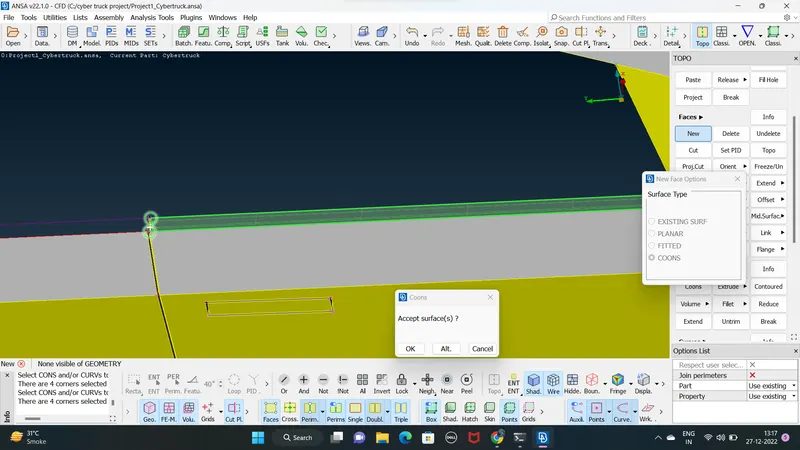
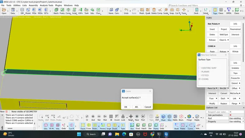
creating faces filling the missing faces there
simple delet the faces than creating new faces respectively using
MENUBAR>TOOLS>TOPO>FACES>DELET
MENUBAR>TOOLS>TOPO<FACES>NEW>CONS
STEP 7: The given model we can see there are penetraction ( intersection ) error we have to try and solve those errors
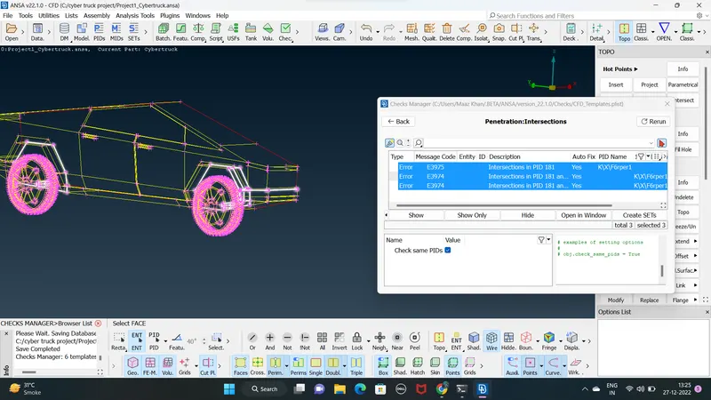
STEP 8 : we can see the wheels shaft have overlaping faces that have creating intersection errors simpaly delet that over lapping faces of a shaft
using
MENUBAR>TOPO<FACES>DELET
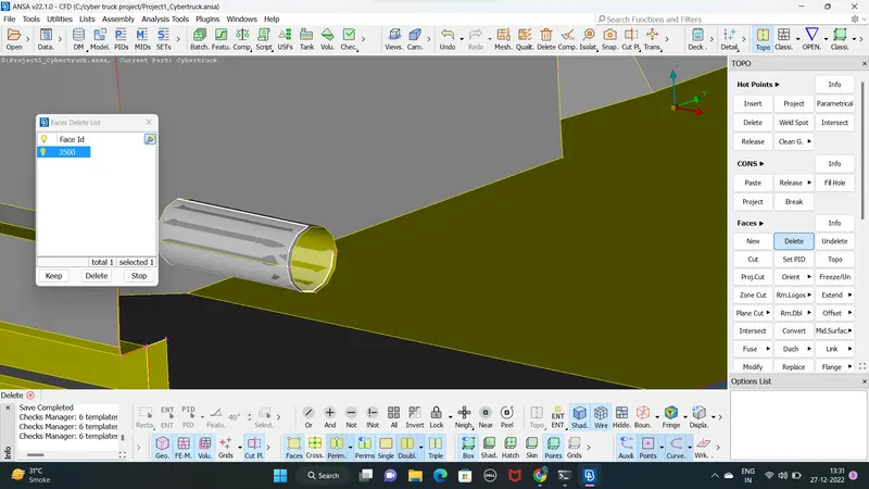
same as a 2nd wheels of the shaft of a model
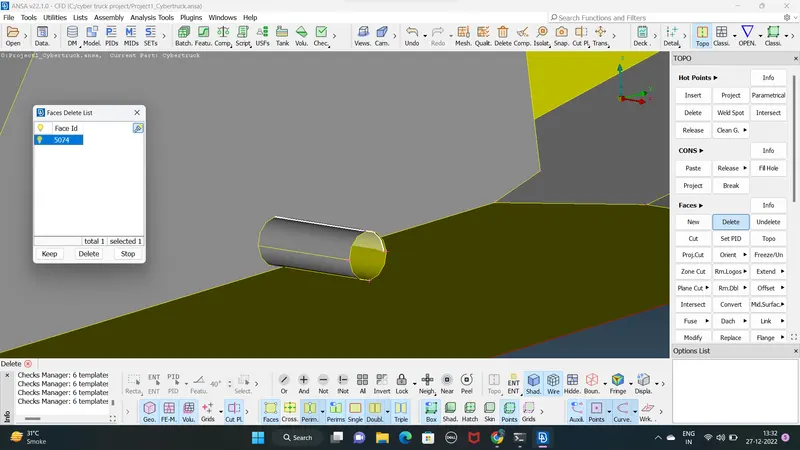
STEP 9: After checking and performing topo CLEAN-UP for the entire half part of a model we should do a final geometry check to find if there any remaning small crack and unchecked faces which is not good for geometry
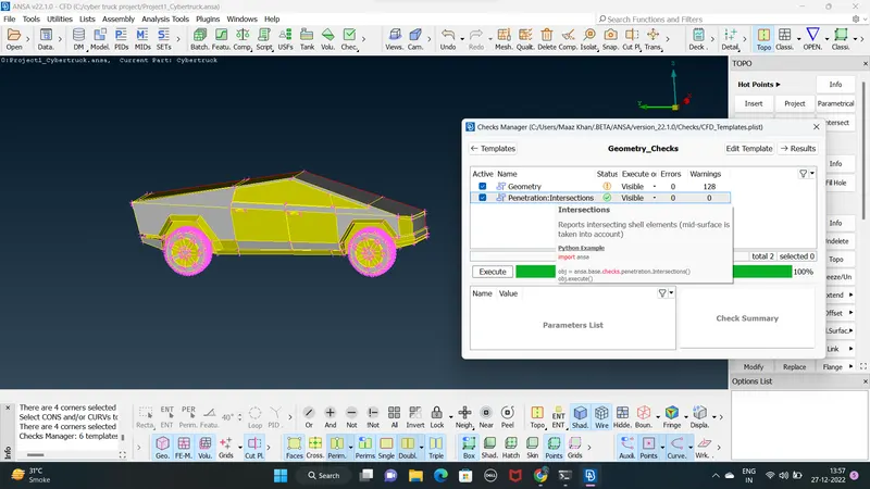
- single and convex cons showing only cut half part of a model
- as we can see there are no any intersection errors present on a half part of a model
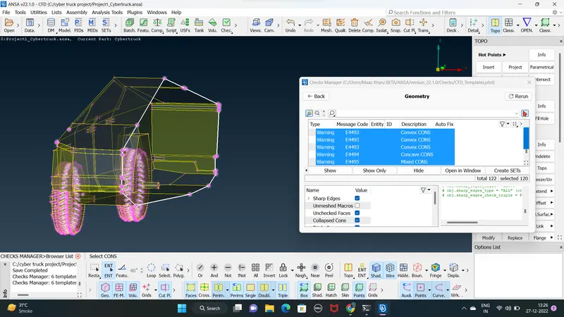
STEP 10: after clearing all the topological errors ( geometrical error ) we can go with assining PIDs then Meshing
ASSINING PIDs :
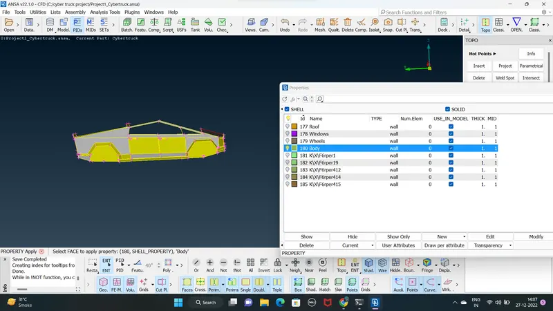
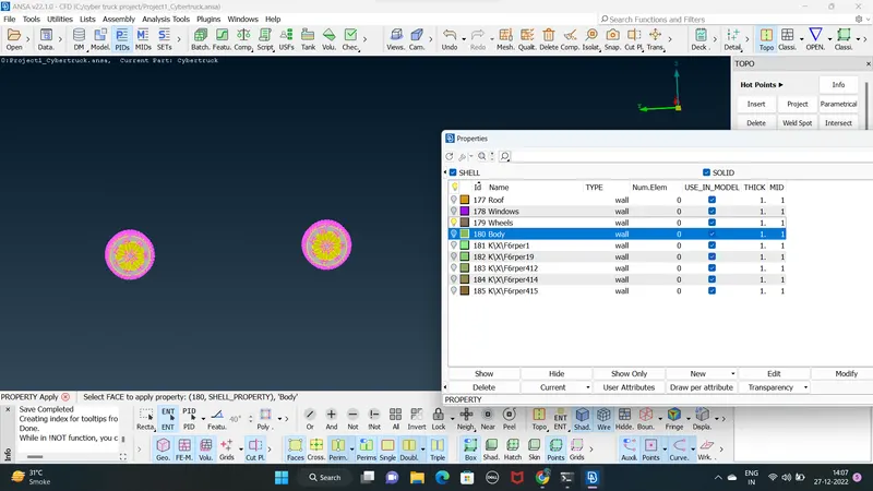
STEP 11: assining PIDs for region of the given model using
MENUBAR>LISTS>PROPERTIES
NEW>SHELLPROPERTY>REMAIN NAME AS PR WE CAN ASSSIGN THE PIDs NAME
BODY:
WHEELS:
WINDOWS:
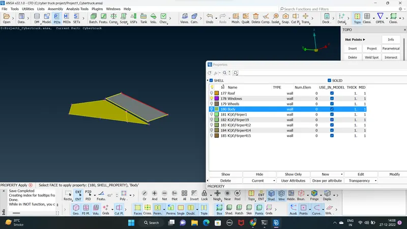
ROOF:
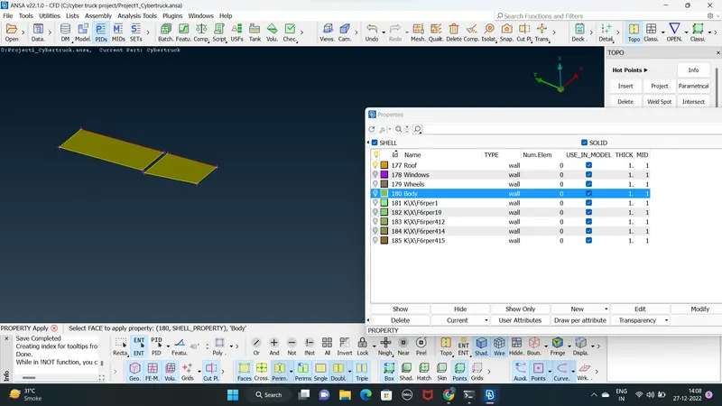
STEP 12: remaning pids simple compress using compress option
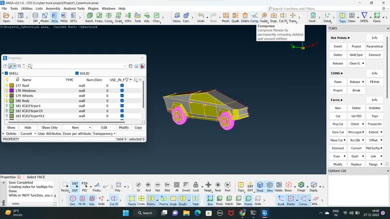
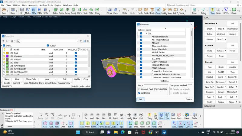
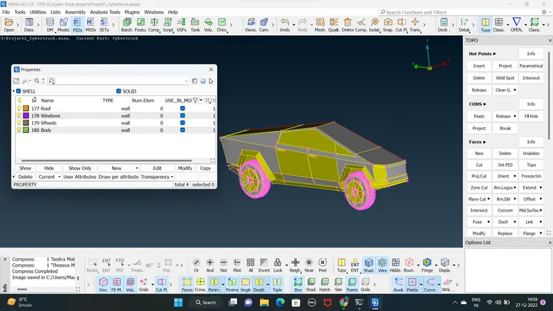
MESHING :
STEP 13: Quality criteria i am giving all the region of a model skewness =0.5
min length of a qality criteria = 0.2
max length = 6
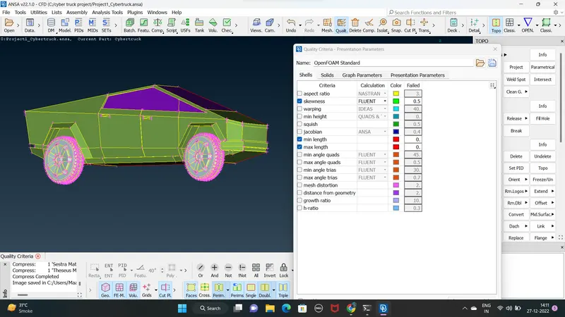
WINDOWS AND WHEELS MESH TARGET LENGTH = 2mm
CFD spacing parameters i give
min =1
max = 3
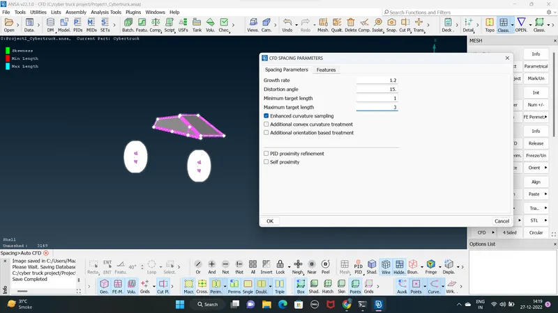
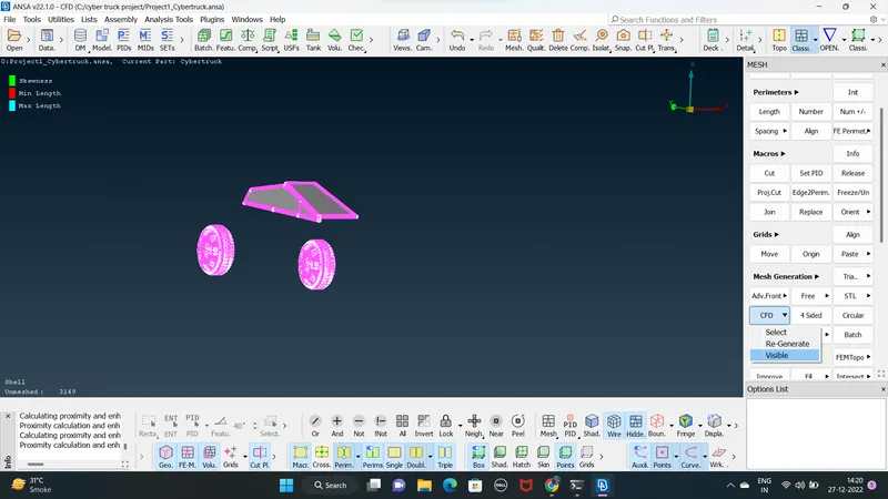
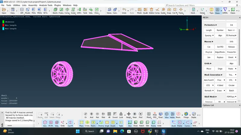
- freeze that the meshing part using MENUBAR>MESH>MACROSE>FREEZE&UNFREEZE
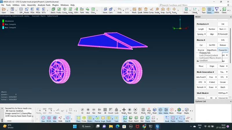
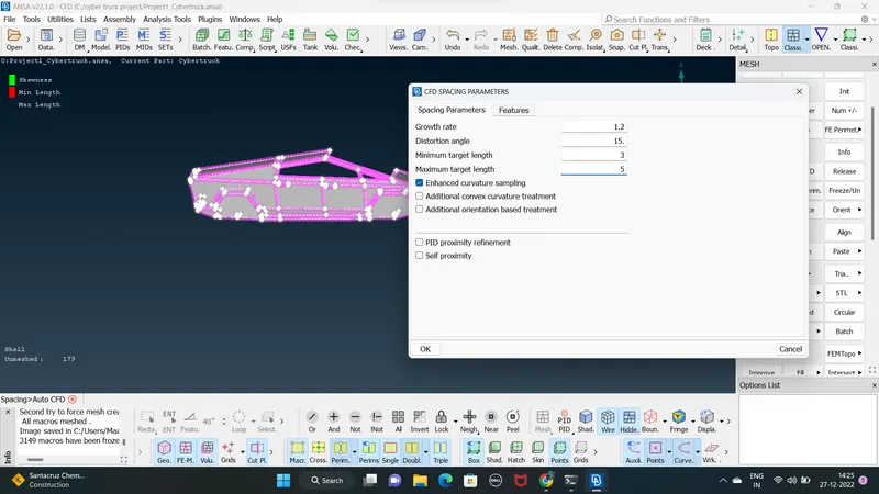
BODY AND ROOF MESH TARGET LENGTH = 4mm
CFD SPACING PARAMETER I GIVE
min = 3
max =5
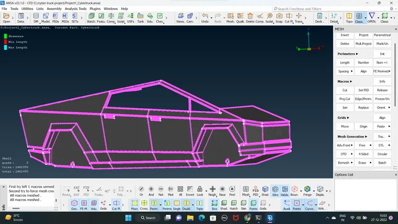
STEP 14 : after completing meshing unfreeze the model using unfreeze left click of a mouse show in the above fig
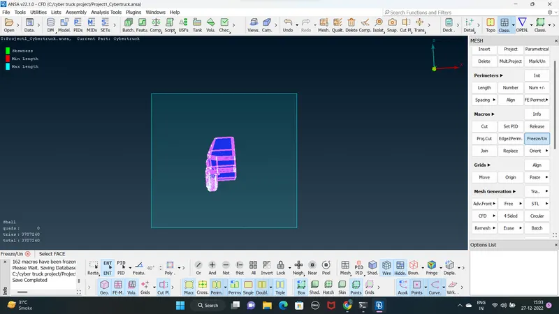
- since the whole half of the model is meshed we can just simply transforme the model to create a whole cyber truck mdel
STEP 15 : select the entities to get transformed press right click choose the mirror 3 points plane under symmetry and select any three points on the end surface of the model and again press right click
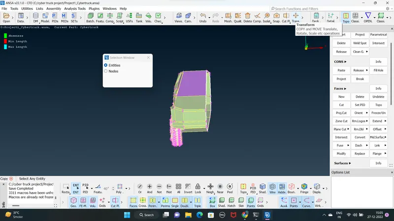
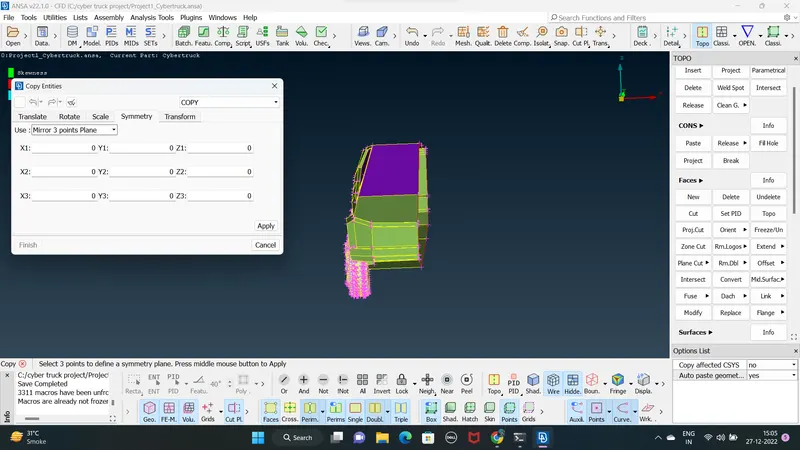
STEP 16 : now the car has been transformed
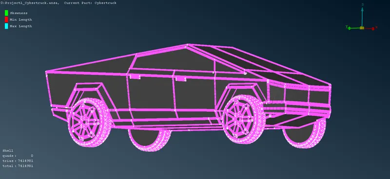
STEP 17 :
WIND TUNNEL :
- Data for wind tunnel as a follow .
- the wind tunnel dimension are if X id the length of car model
- front of wind tunnel is 4x from the car
- rear of wind tunnel is 6x from the car
- top of wind tunnel is 3x from the car
- side wall of wind tunnel are at X from the side potion of the car
- bottom of wind tunnel is in close proximity of wheels
- Points are created by using (Relative option )
MENUBAR>TOPO>POINTS>RELATIVE
STEP 18: Measure the length of a model ( total length of the cyber truck 50906mm) i consider 6000mm
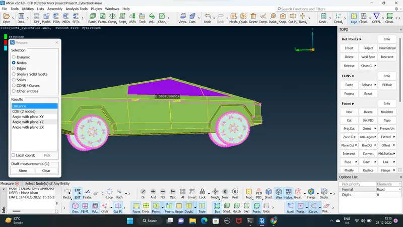
STEP 17: creating a refrance point at a bottom ( insert a hot point in bottom of a model using insert hot point )
using a hot points lest create a node using realative option in a bottom -Z direction ( -1000)
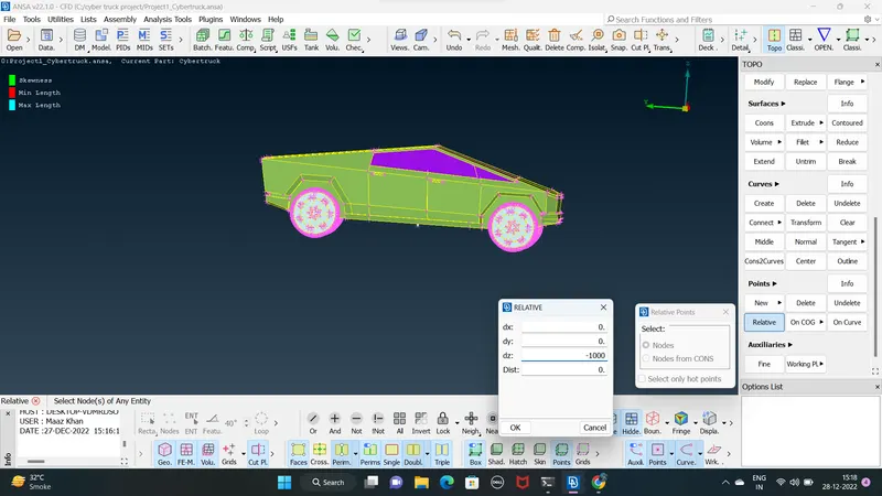
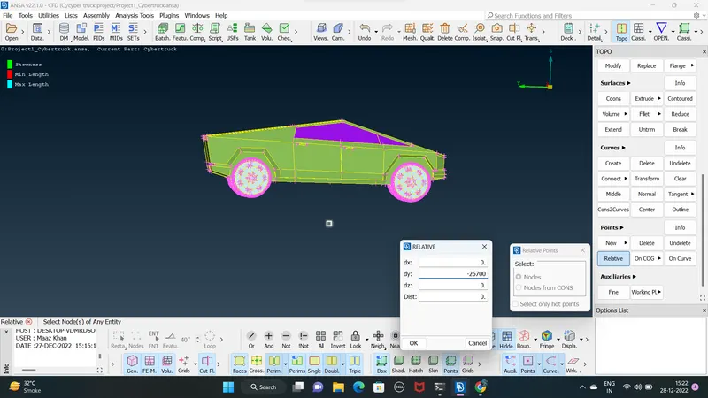
STEP 18 : with the help of refrance point at front nodes -Y direction ( 2700+4X6000 =26700mm in front direction )
front of wind tunnel is 4X of the car
with the help of refrance point at rear +Y rear of wind tunnel is 6X ( 3300+6x6000= 39300 )
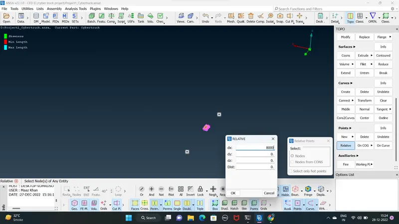
STEP 19: creating front and rear nodes using refeance nodes length distance at -x and +x direct at
select the refrance 2 nodes put the distance of +x at 8000
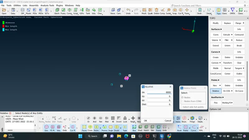
STEP 20: after completing the bottom nodes simplay we select tha center nodes refrance at the top faces to creating top refrance points at a car
+z axis at 20600
then we have to connect the points using curve option to create the walls
MENUBAR>TOPO>CURVES>CREATE
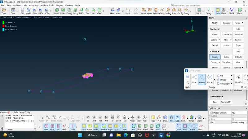
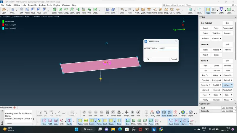
STEP 21: we can offset the bottom surface at the top surface and we can delet the unnessary points and deleting the created curve then with tha top and bottom surface refrance can create the side faces
DEFINING THE PIDS FOR THE WIND TUNNEL
TOP_FACES
BOTTOM_FACES
SIDES_FACES
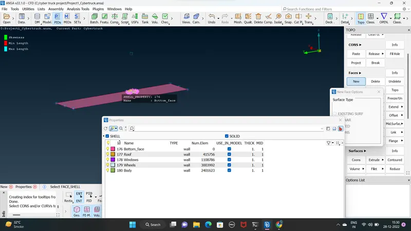
OFFCET VALUE IS - 20600 at the -z direction
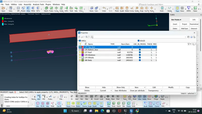
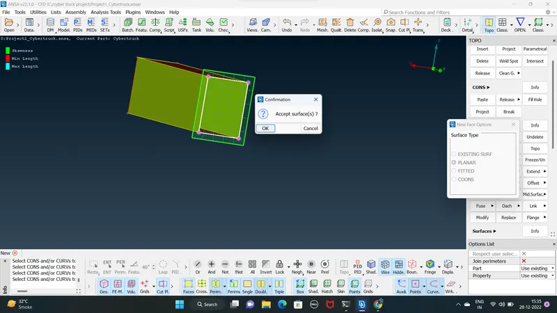
CREATING SIDE FACES USING PLANNER
MENUBAR>TOPO>FACES>NEW>PLANNER
SURFACE MESHING :
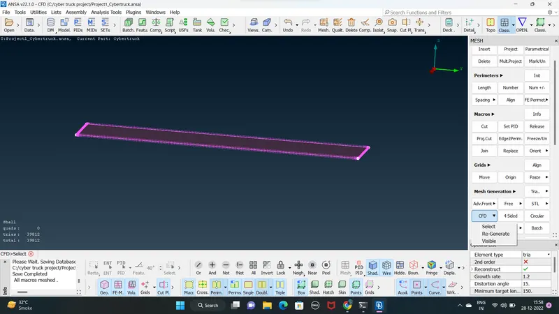
WIND TUNNEL : 200mm to 450 qality criteria
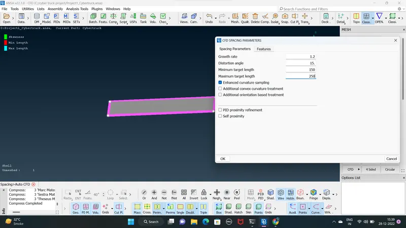
BOTTOM_FACE
CFD SPACING PARAMETER LENGTH USING
min= 150
max= 250
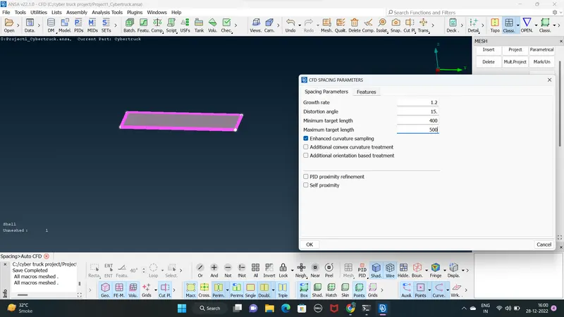
TOP FACE
min =400
max= 500
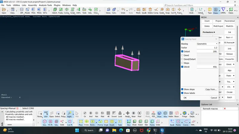
SIDE FACES performe growing mesh
manul cfd spacing
Dstart = 200
Dlimit = 450
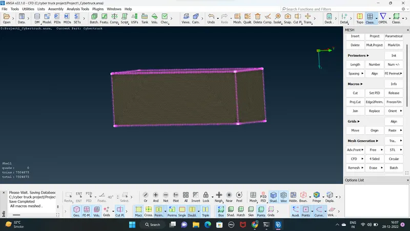
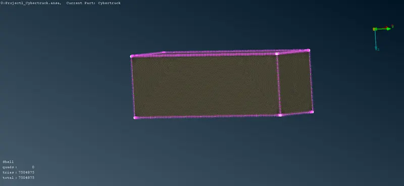
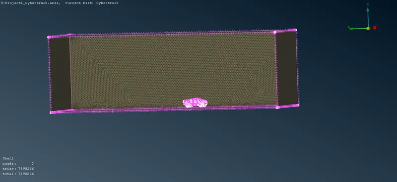
THE final mesh
since performing volumetric mesh required 2-3 days so we are not performing it
LEARNING OUTCOMES:
- learn how to create a wind tunnel and using spacing option in surface meshing help in having mesh length along the surface
- learn how to clear any off elemnts created while meshing using reconstract option
- using the mesh modifiying tools like move . split. and smooth option
- identifying & cleanup of the topological / geometrical errors
- use qality cretiria tools also learnt various option under the shell parameter such as skwness, min length , max length
- set up wid tunnel as per given dimesnions for external flow CFD analysis and surface mesh of wind tunnel
CONCLUSION :
- created wind tunnel for external aerodynamic analysis
- surface mesh is generated with the required element size
RESULTS :
complete the tesla cyber truck model with wind tunnel ANSA
https://drive.google.com/file/d/1LflEerm1jvHcYPEo_uEEhdplodBaVQk6/view?usp=share_link