Week 3 Challenge : CFD meshing on Turbocharger
AIM : CFD MESHING ON TURBOCHARGER
OBJECTIVE : The main objective of the given challenge is to perform surface mesh on turbo charger and also geometry clean up with the surface mesh for the PIDs as perform surface mesh with given target length as per PIDs
- Blade stage-1 = 1 mm
- Blade stage-2 = 1 mm
- Impeller = 2 mm
- Shaft rotor = 1 mm
- Turbo casing = 5 mm
- Compressor casing = 5 mm
- Inlet casing cover = 5 mm
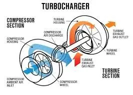
TURBOCHARGER :
- IN an internal combustion engine a turbocharger called a turbo is a faced induction device that is powered by the flow of exhaust gasses
- It use this energy to compress the intake gas forcing more air into the engine in order to produce more power for a given displacement
HOW DOES IT WORK :
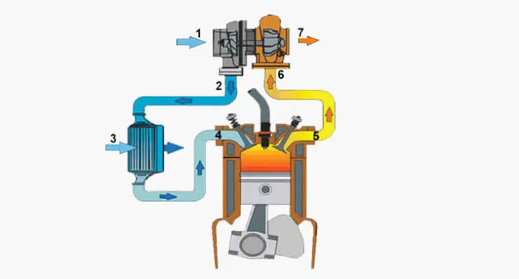
- A turbo is made up of two halves joined together by a shaft. On one side, hot exhaust gasses spin the turbine that is connected to another turbine which sucks air in and compresses it into the engine
- cool air enters the engines air intake and heads toward the compressor
- The compressor fan helps to stuck air in
- The compressor squeezes and heats up the incoming air and blows it out again
- Hot compressed air from the compressor passes through the heats exchanger which cools it down
- Cooled compressed air enters the cylinder air intake the extra oxygen helps to burn fuel in the cylinder at a faster rate
- since the cylinder burns more fuels it produced energy more quickly and can send more power to the wheels via the piston shafts and gears
- waste gas from the cylinder exits through the exhaust outlet
- the exhaust gas leave the car wasting less energy
STARTING THE ANSA :
click the ANSA in the start menu to open the ANSA software
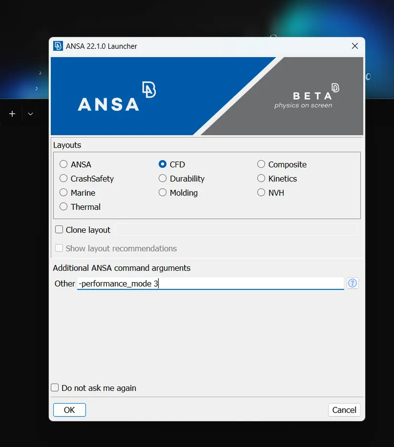
After clicking the ANSA the above window pops up in the above poped up window select the CFD in layouts
in additional ANSA command arguments change the other to - performance_mode 3 than click OK button
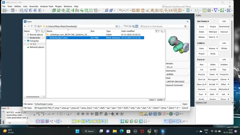
Open the downloded Turbocharger.ansa file as shown
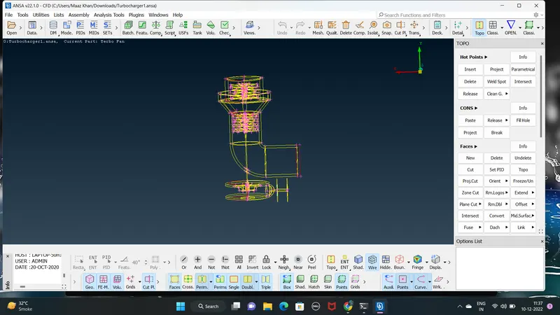
on opening the model you will see the following
single cons , Red cons , or Double cons and hot points
our first target would be to remove the Red cons
Turn on the shadding mode by using the red encicied button as show in the figure ( SHADE)
Turn on the PID mode by clicking the buttons
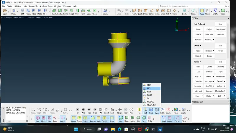
The fllowing is the view of model in PID MODE
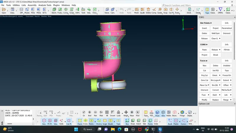
using ctrl+Shift you can turn on the wireframe mode ctrl+shift+Mouse left / right / middle button can be used to orient the model the way we want to observe
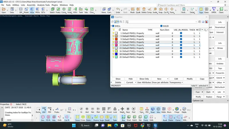
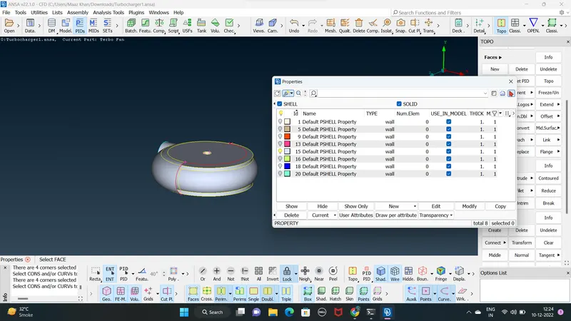
turn on PID properties using red encircled button as shown above a new window pops up named properties
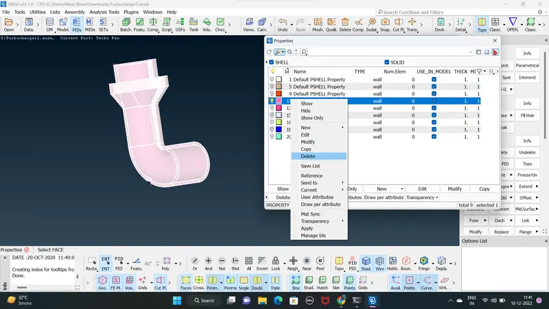
by turning off the bulb in the properties window we identify that the 11 default PSHELL property was overlaping with the 20 deafults PSHELL property this overlaping can be removed by deleting the 11 default PSHELL property
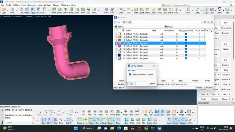
on click the delet a new window named delete option pop up in that click the ok button and that PID is deleted
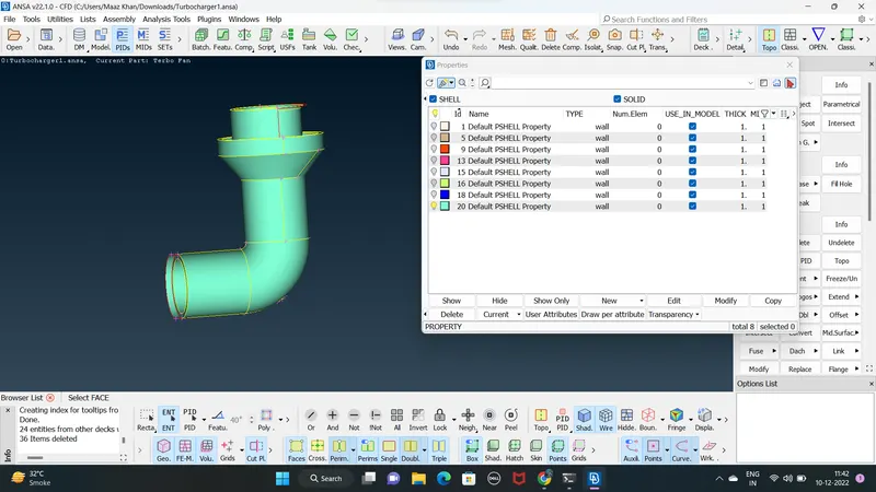
on turning on the bulb of 20 default pshell property and in the properties window we observe that unwanted overlaping body is deleted
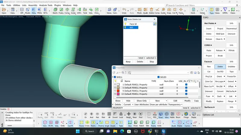
now we see on overlapping or extra surface encircled in red as show in fig
we delet that surface by using delet under faces in topo and then selecting the surface required to be deleted a new window pop up face delete list in the window select the face ID and click the delet button
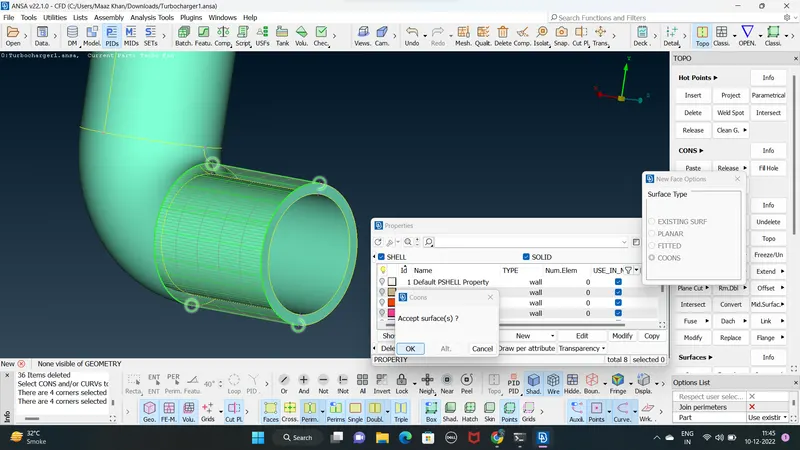
the new surface is created using new under faces in topo on clicking the new a window named new face option pop up in that we select the coons
then middle click of the mouse a temporary surface is generated along with the new window poping up coons confirming with us the temporary surface generated is OK OR NOT
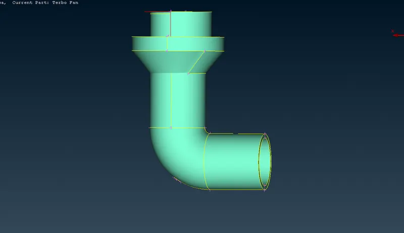
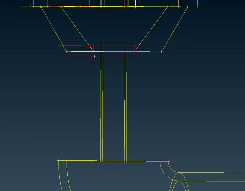
now we see there is a red cons presesen in the green area as show in above figure we will try to resolved this
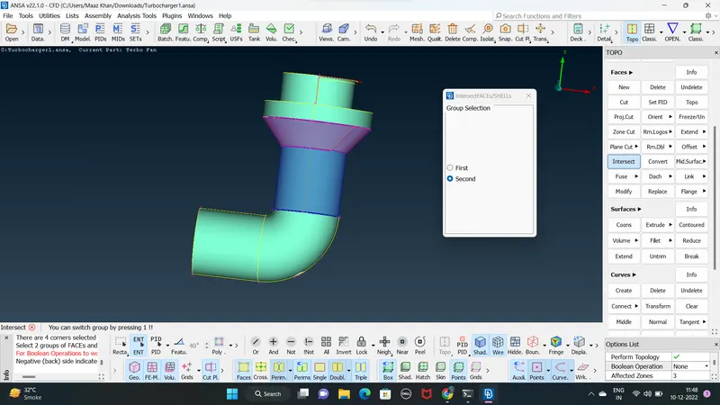
using intersection under faces we try to check the intersection erroe first we select the purple highligted surface and the secound surface selected is blue end the press the middlr mouse button
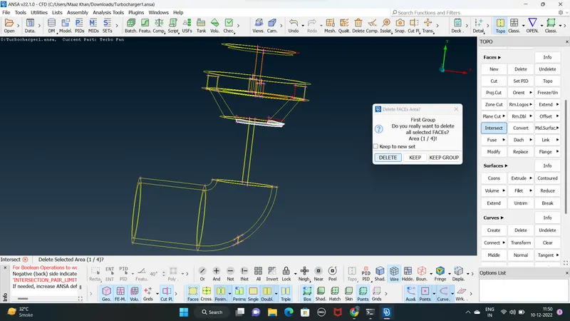
we delet the first face area as this not required
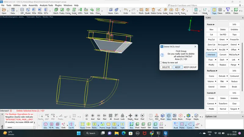
we keep the 2nd face
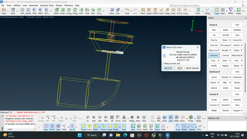
we delete the 3rd face is not required
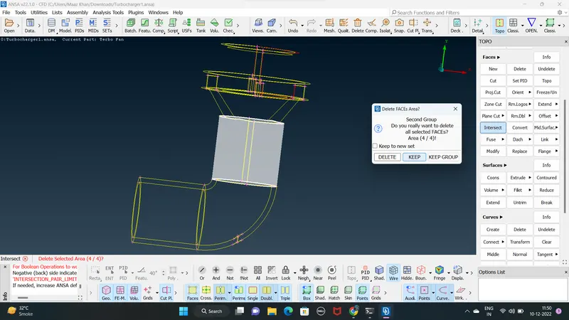
we keep 4th face is required
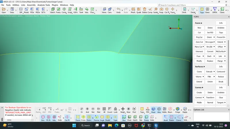
after the intersection is done we observe that the edges of the at the end portion is not proper
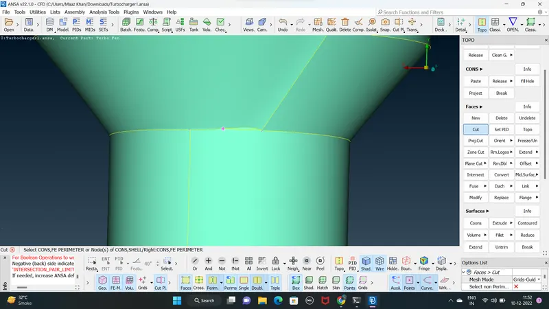
we create cut using the cut option under faces in TOPO
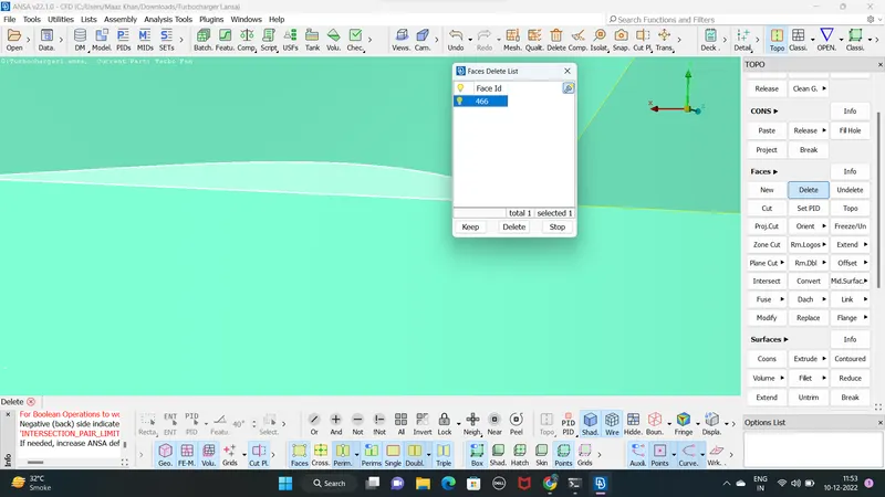
we delete the unwanted face as show in figure we also deleted the unwanted hot points generation due to cut option we used
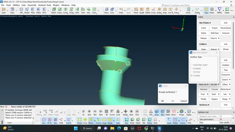
create a new face surfaceas show above fig and remove the curvy edge error
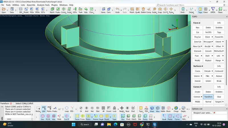
we select transform under curves in TOPO and select the curve press the middle mouse button / scroll and then select the hot points starting from the arrow till other hot points where the curve has to be fromed as show in figure
simillarly we follow transform option to genereate the curve on the other side
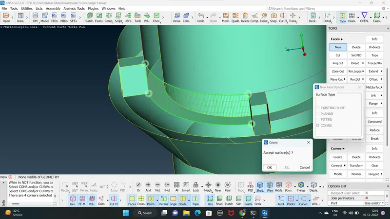
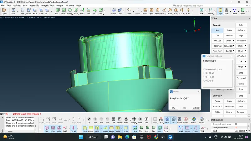
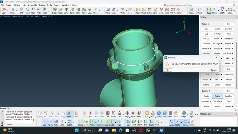
once the surface is genrated we delete the curves that we created to generate the surface
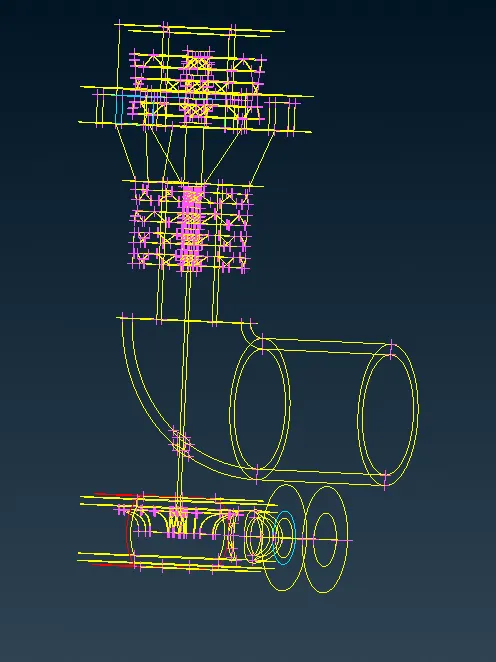
now we attempt the remove the red cons presents in the impeller casing
we create hot point insert
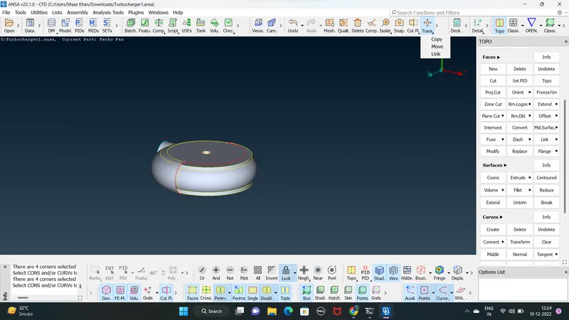
now we are transforme the surface
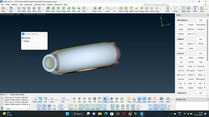
select the entity do the middle click of mouse select entity face we have to copy ( mirror )
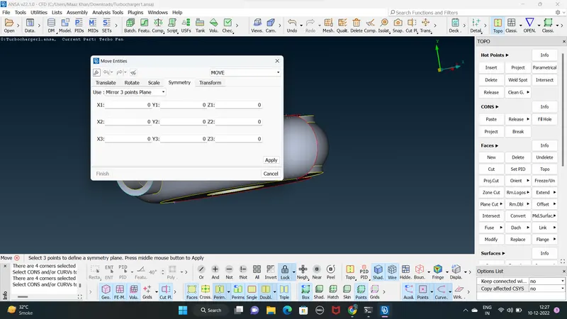
mirror 3 points plane
select the hot points and generated the mirror plane
after genrating plane same as the copy have to tou holde on mirror face that we fill tha hole using fill hole option show in fig
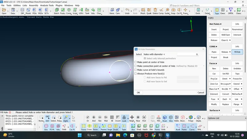
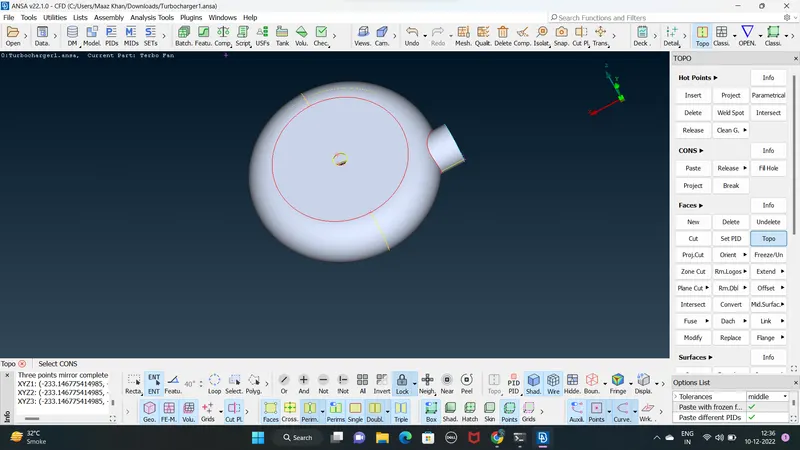
Then we did a topo for the impeler casing
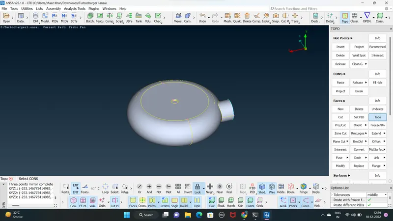
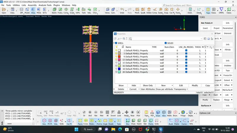
we perform a geometry checks and found intersection errors we attempt to remove these intersection errors
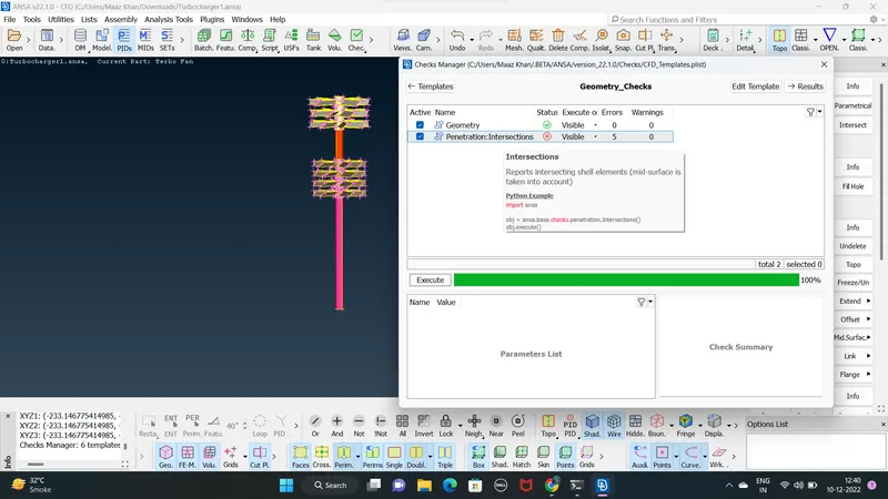
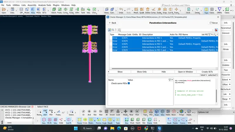
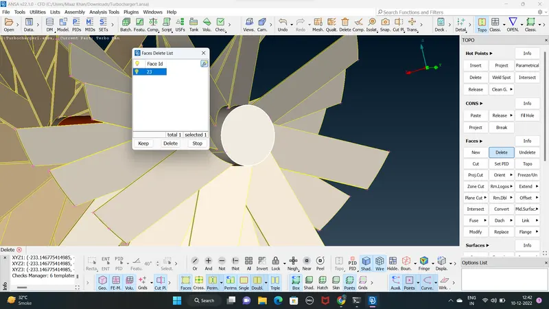
similary we delete the unwanted surfaces near the shaft blades
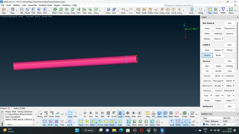
now we use project option in CONS on the shaft surface to delet the overlapping surfaces
and simplay delete the project face
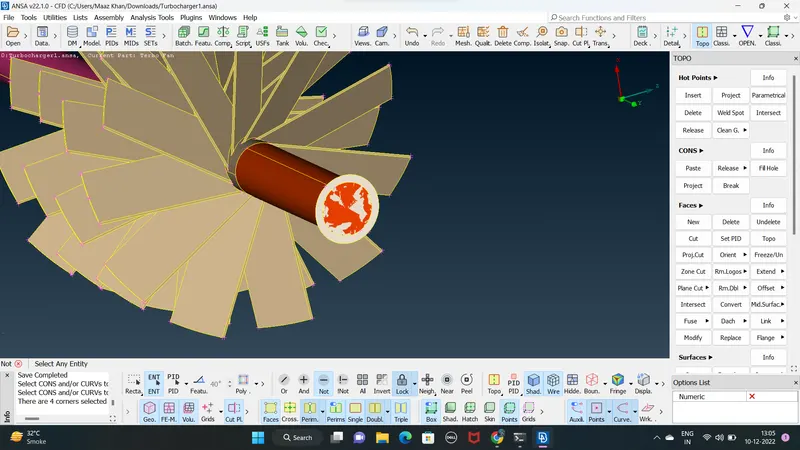
delet overlapping surface
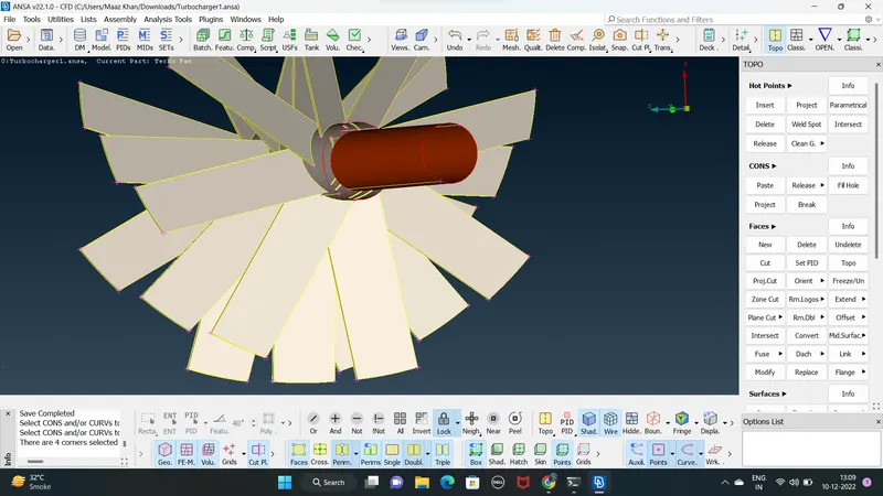
see in figer its single cons there after deleting the surface simplay selet fece new and select cons to create a new face there
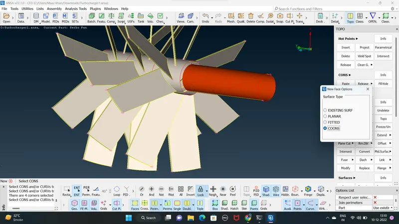
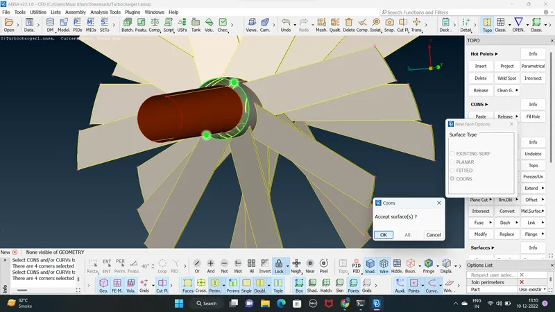
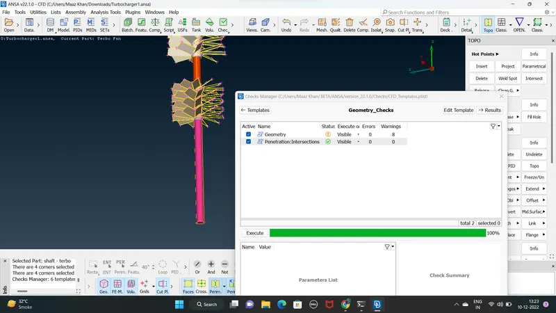
now we again geometry cheack not found any intersection erroe at the shaft
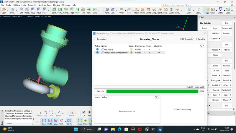
now we run the geometry checks for the entire geometry and found four intersection errore
we attempt now to resolve these intersection error
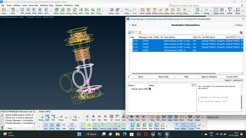
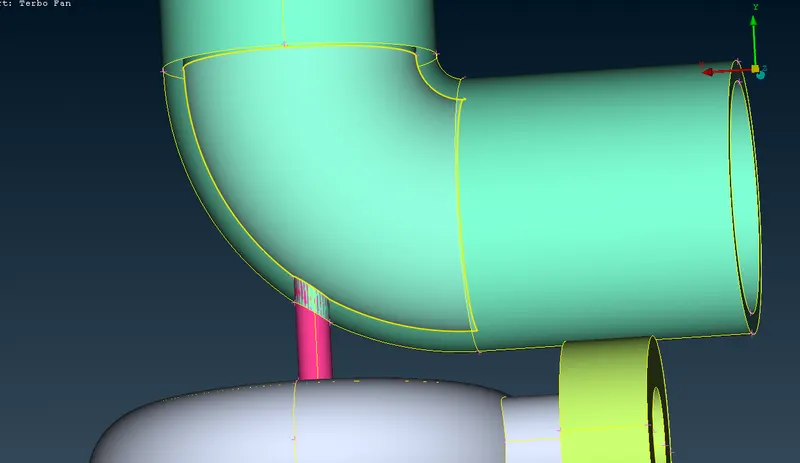
we delete the overlapping surface and delet the portion of shaft in the compressor casing
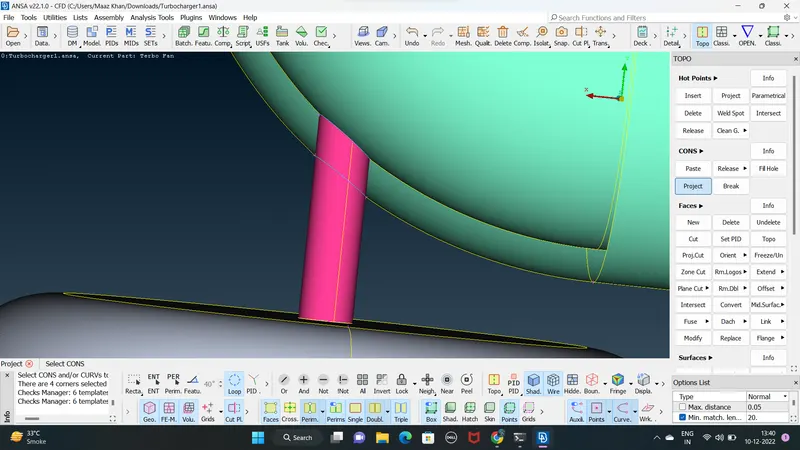
now we projecting the curve or coons present on the compressor casing onto shaft so that we remove the faces in the casing thickness
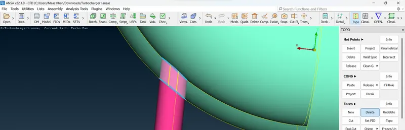
we delete this face
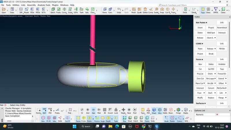
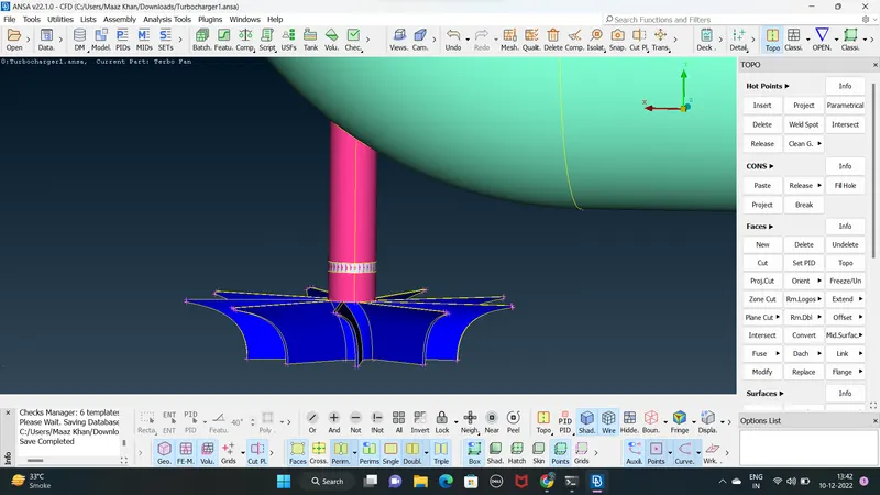
now we have projected the curves near the impeller casing into the shaft and delete the potion of rotor shaft
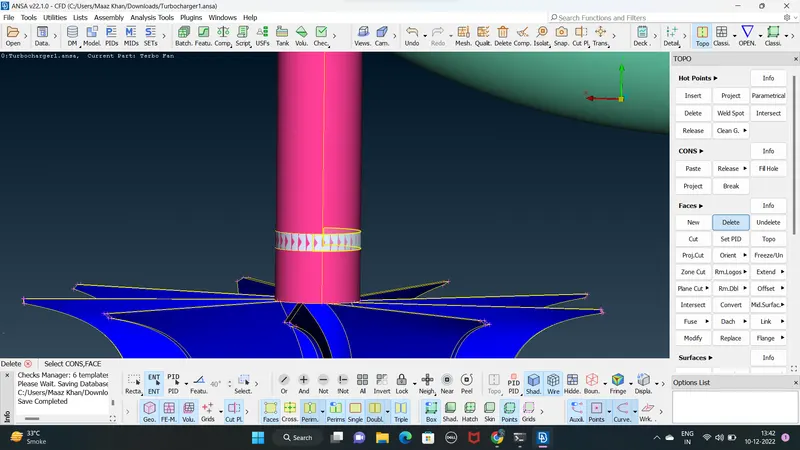
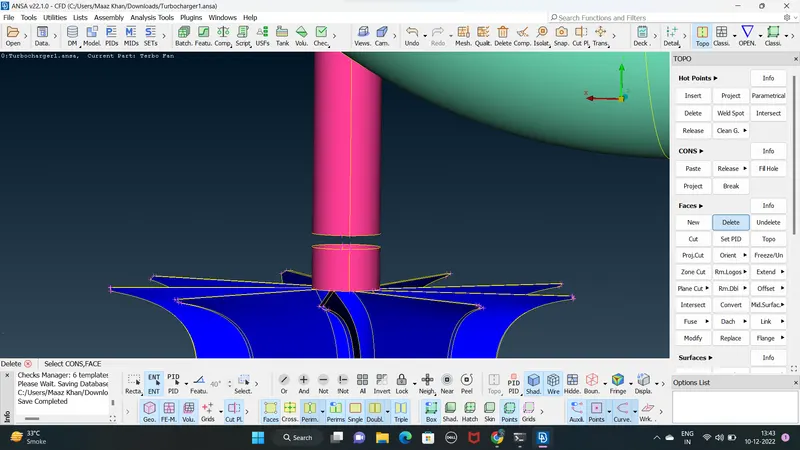
check again geometry we founf 2 intersection errors at the junction of impeller and shaft
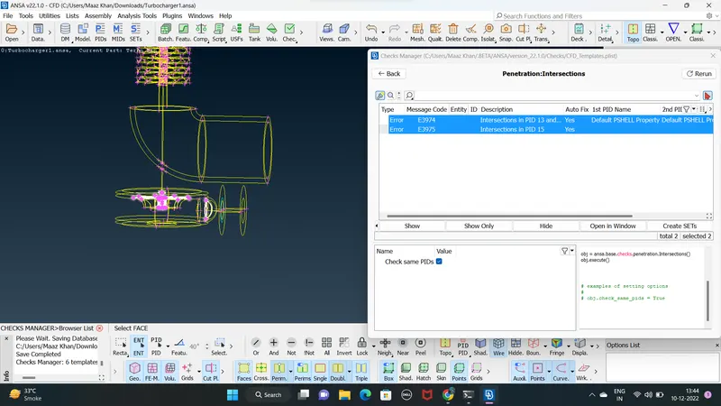
show in below figer overlapping face simpley delet this face
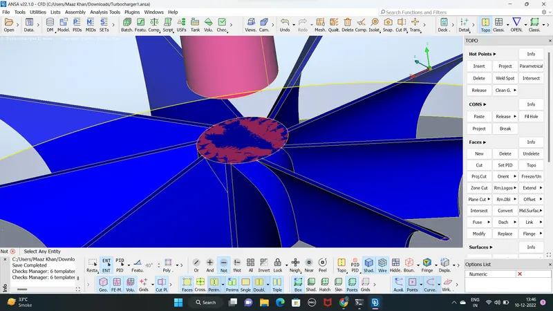
its a on PID thats why use project option select shaft cons the select impeller face and create new cons then delet this face and its found a single error the apply the TOPO to joints the faces and clear the single cons error
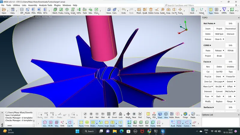
after clearing all the intersection errors fill the gaps using cons new PLANNER
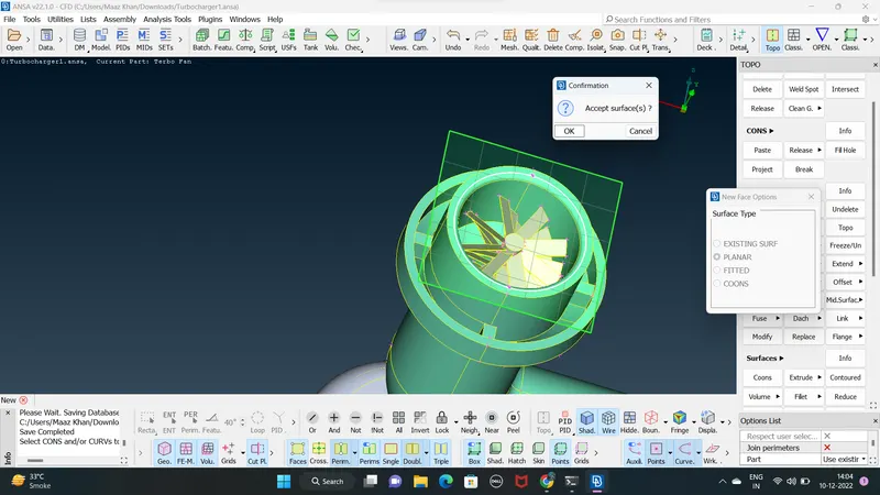
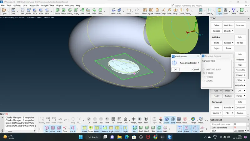
showing some gaps we will close the gap also
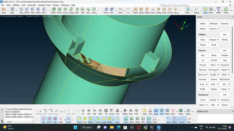
select face new CONS selects cons then create faces fill the gap
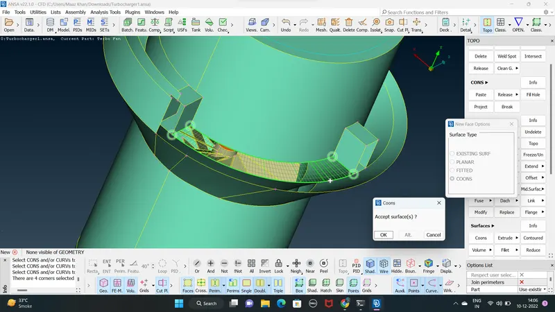
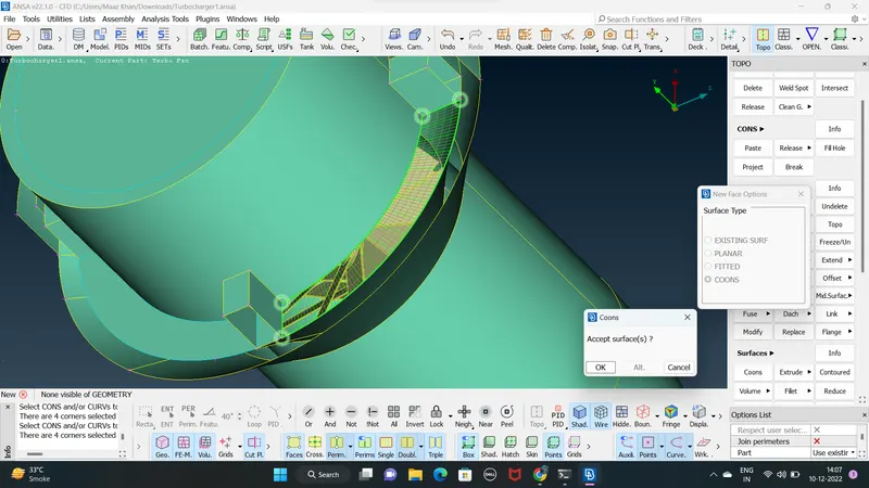
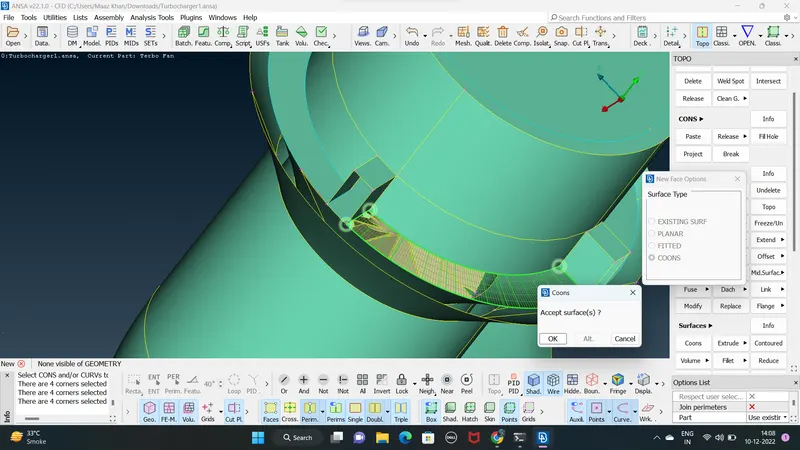
completing and filling all the gaps lets assign the PID
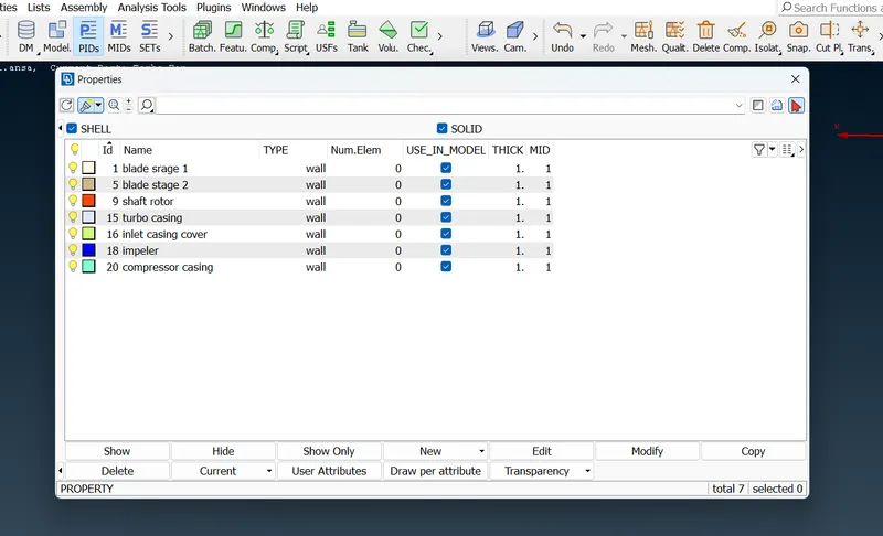
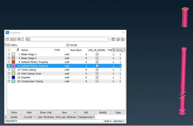
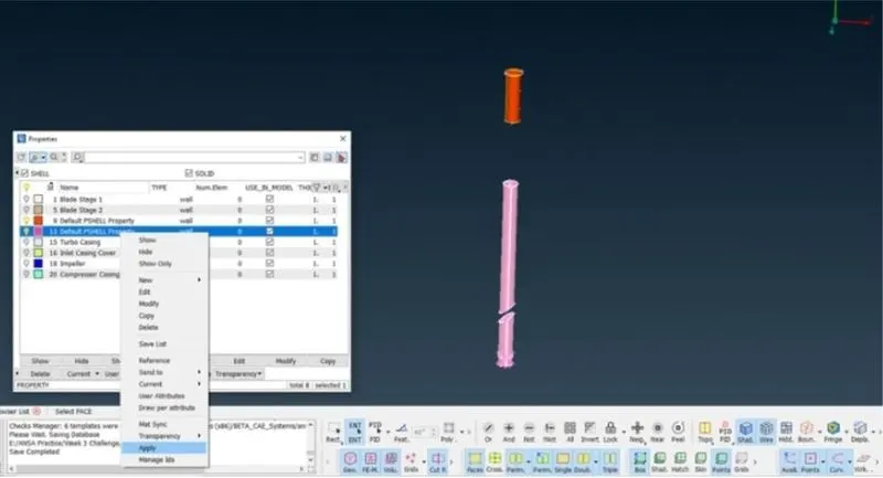
now PID Assigned that unwanted pid simply ued compress option to clear the unwanteed PIDS
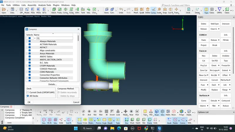
SURFACE MESHING :
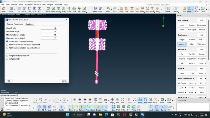
now we start with the surface meshing with target length of 1 mm blade stage 1 , blade stage 2 and shaft

surface meshing using paremeters spacing show in figure AUTO CFD
TARGET LENGTH 1MM ( BLADE_STAGE 1 ,BLADE STAGE 2 ,SHAFT )
1mm target length using parameter and macrose
maximum length = 1.3 mm
minimum length = 0.5 mm
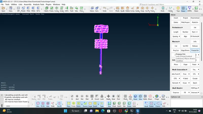
after meshing using freeze option to freeze meshing object
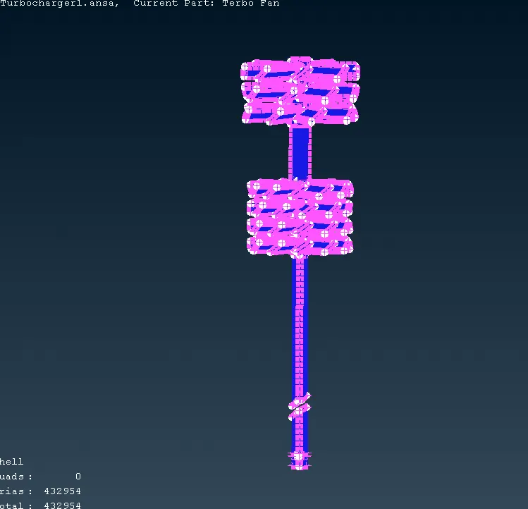
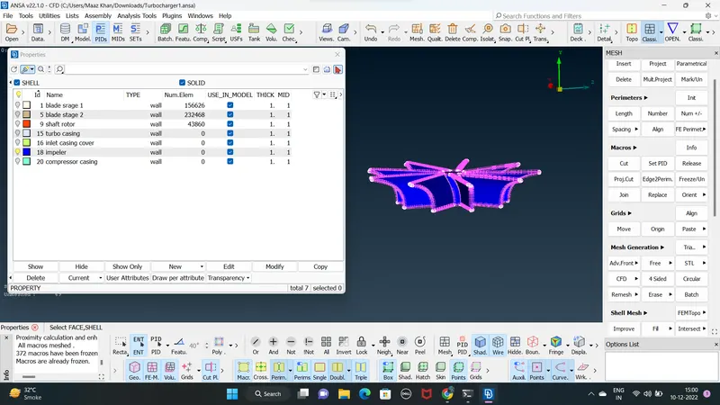
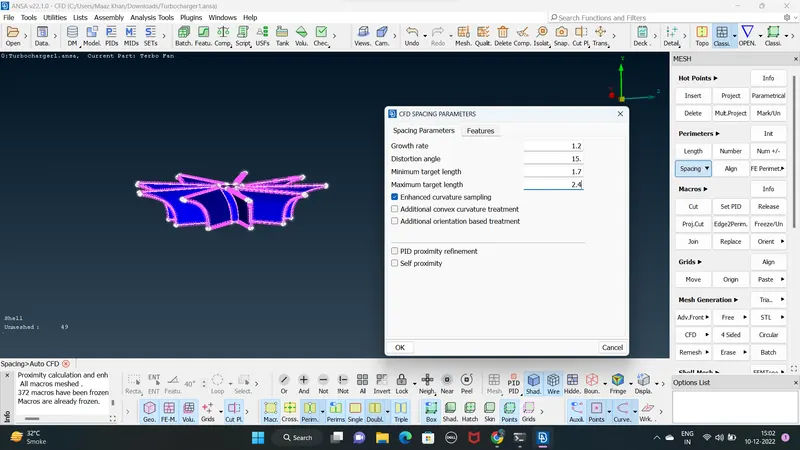
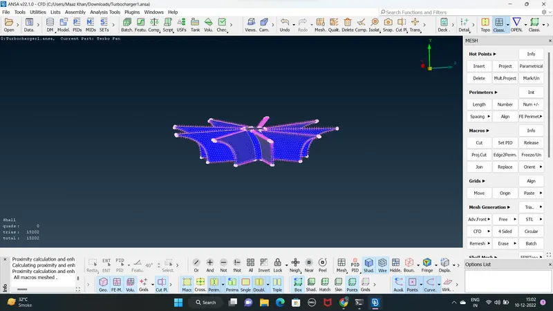
TARGET LENGTH 2mm ( IMPELER )
2mm target length using parameter and macrose
maximum length = 2.4mm
minimum length = 1.7mm
TARGET LENGTH 5mm ( COMPRESSOR CASING , INLET CASING , TURBINE CASING )
5mm TARGET LENGTH PARAMETER AND MACROSE
maximum length = 5.3 mm
minimum length = 4.7 mm
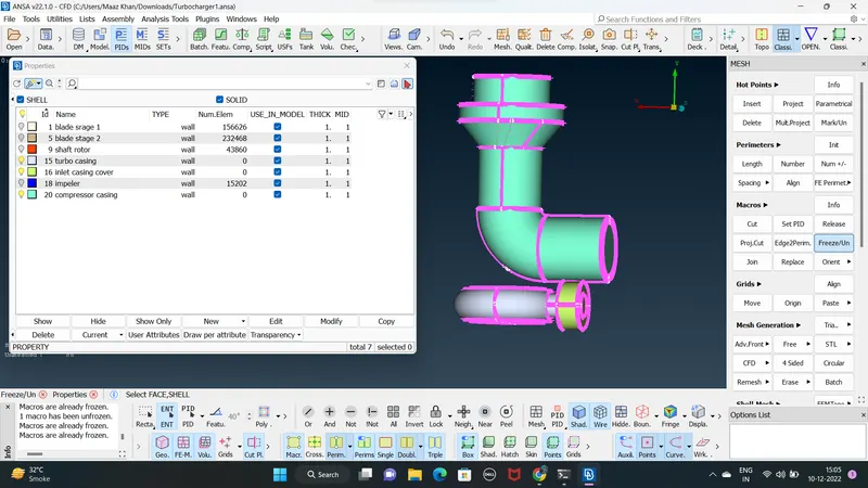
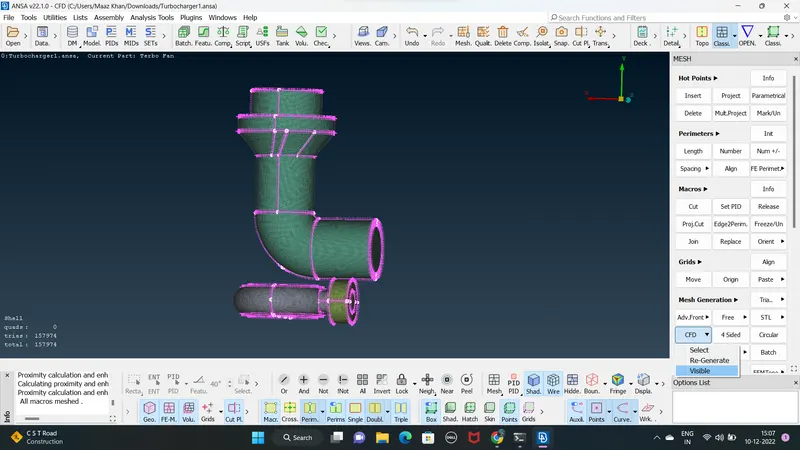
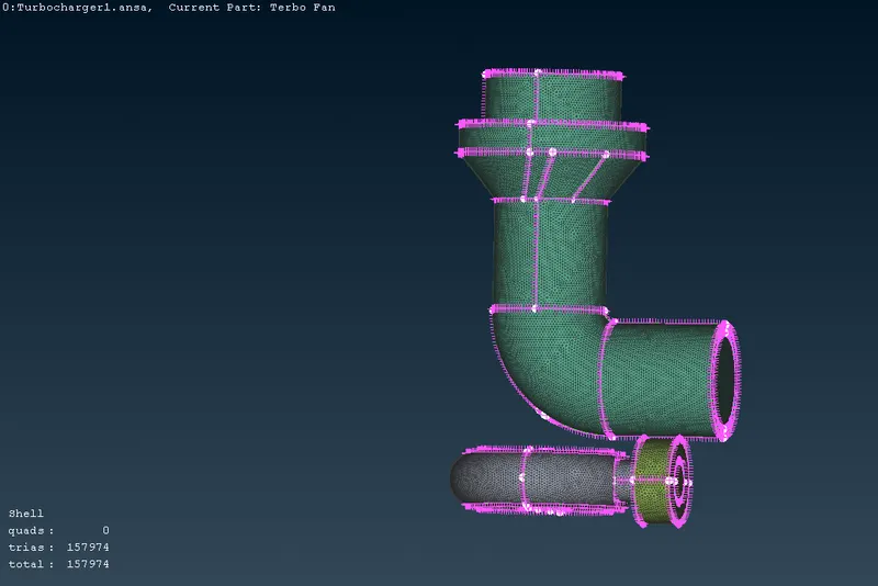
After complete surface meshing unfreeze the model
using freze / unfreeze just / LEFT CLICK TO UNFREEZE THE MODEL ( TURBO CHARGER ) as show in fig below
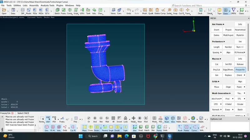
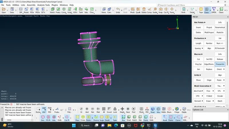
AFTER COMPLETE SURFACE MESHING
LETS START THE VOLUMETRIC MESHING
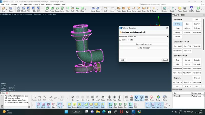
use DEFINE THEN OK WITH WHOLE OBJECT BODY (TURBOCHARGER )
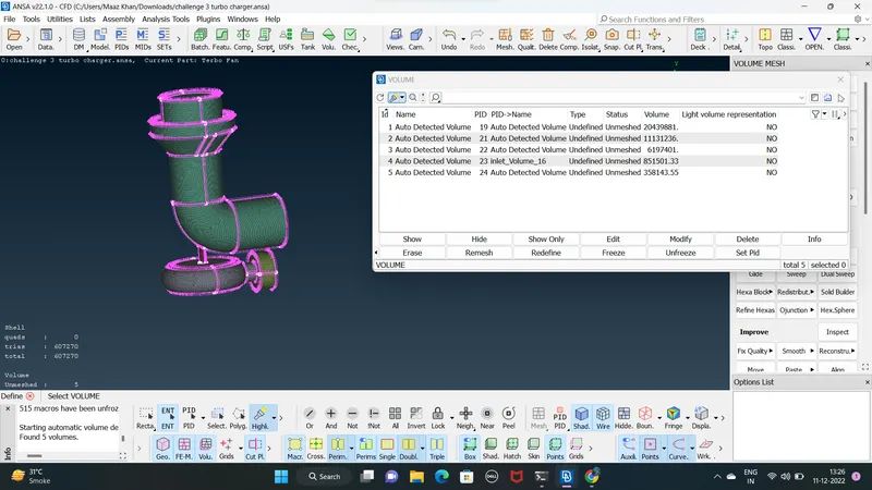
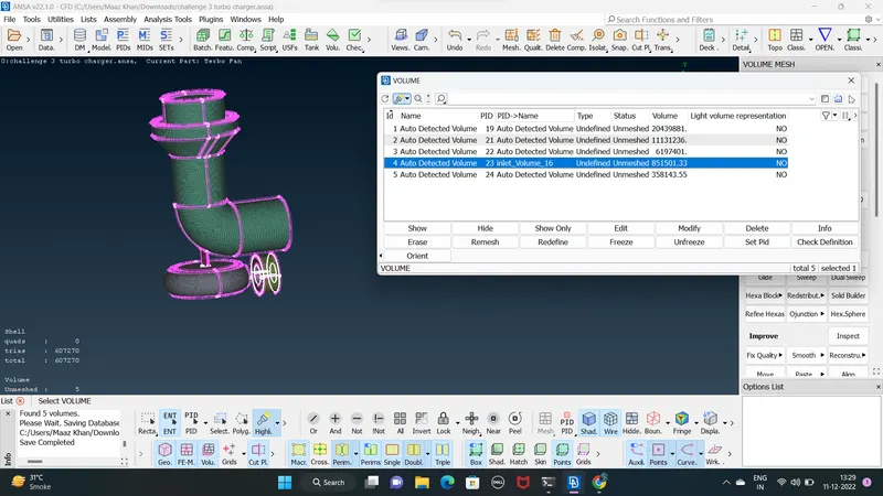
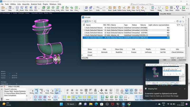
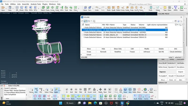
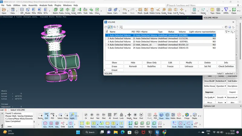
deleting the external volume of the components
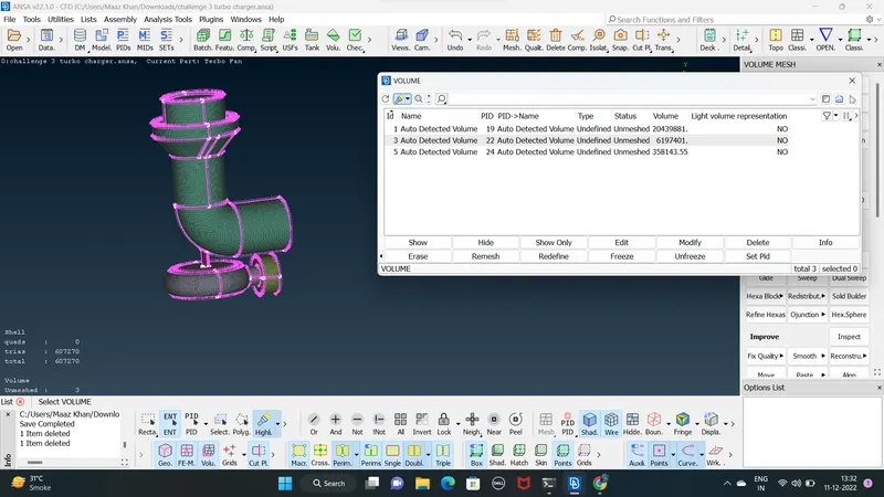
its click the undiffien unstracture ( TETRA CFD ) meshing with 3 volumes of list above figure
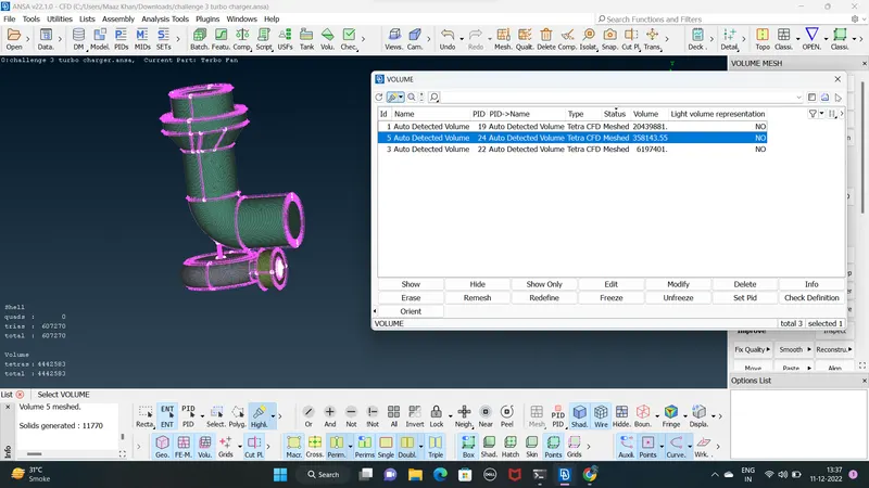
complete the tetra cfd meshing
the cut section view using XY cordinates of cut section view
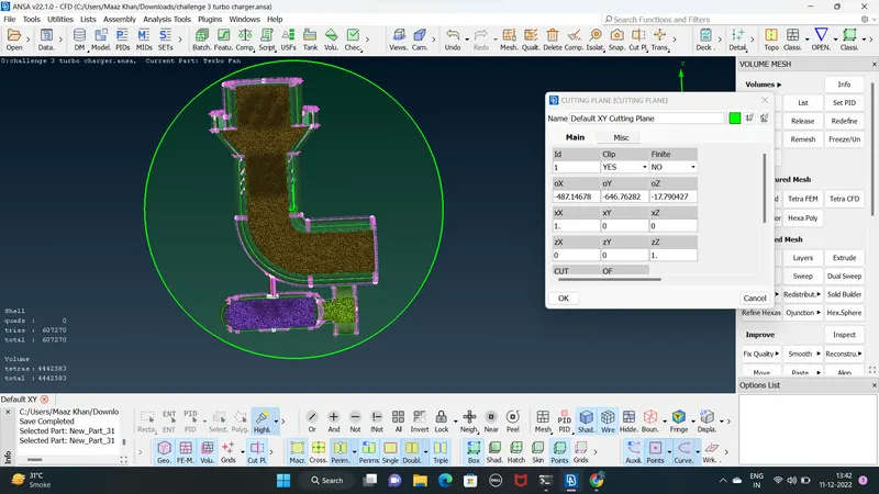
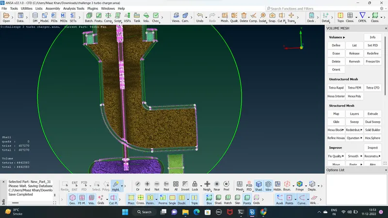
creating xy cordinates cut plane
ansa model link
https://drive.google.com/file/d/1CYkcwxwcZEXN3RSKN1xX9giLkFbL8v7o/view?usp=share_link