Week 4 Challenge : CFD Meshing for BMW car
AIM:
To clear all the geometric and intersection errors in the given assembly. And to assign the PID for the component respectively. And also with reference to the described target length have to do the surface mesh for each component. Then the surface meshed components must satisfy all the quality criteria. And also to create the wind tunnel to perform the external flow analysis in the BMW - M6.
NEW TOOLS LEARNT:
- Hot points -------> Parametrical (To offset the hot point to input percentage)
- CONS --------> Fill Hole (To fill the hole with proper loop)
- Faces --------> Plane Cut (To cut any faces with respect to the plane generated)
- Faces --------> Offset (To offset any faces with respect to one another)
- Curves ---------> Cons2curves (To draw the curves on the top of the selected CONS)
- Points --------> Relative (To create a point with respect to other point)
- Quality criteria ---------> Skewness, Min length and Max length (To validate the generated mesh is upto the criteria of what we loaded)
- Perimeters ---------> Spacing ---------> Manual (To gradually increase the size of the mesh generation with respect to the growing factor from the Minimum length to the maximum length)
PROCEDURE:
- Geometry Checkup:
After the assembly gets loaded in ANSA, initially we have to go for the geometry check as it will shows all the geometrical errors and intersections error in the geometry. Then we have to manually look for any errors. Doing Faces -------> Topo initially preferable as it will join the nearyby parts that are not intersected properly. As it will also leads to the additional intersection errors. After checking the results of the geometry check we have to clear the error without affecting the geometry of use.
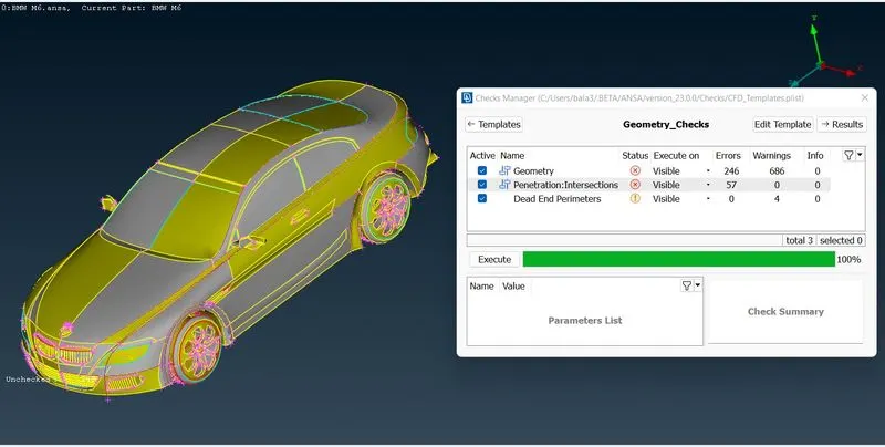
In this particular assembly for clearing all the errors by holding the complete car is difficult one. Instead of that, by the consideration that the car is a symmetrical geometry initially we are going to delete the one side of the car. Then we have to clear all the errors in the another side and do the surface mesh. Then we can do the mirror of the one sided part to get the full geometry.
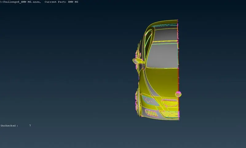
2. Error Rectification:
- Smoothing of Perimeters - It is observed that the perimeter of the each component in the assembly are distorted and had sharper edges. It is due to the perimeters doesnot have proper length when loaded in ANSA. So we have to go to the Classic Mesh --------> Perimeters --------> Length. On that put the value of perimeter as lower to get refined edges in the perimeter.
- To clean up the geometry for the particular grill, initially we have to delete the unnecessary faces that causes Triple CONS in it. And also we have to convert it into a single volume so as to make the selection of the volumetric mesh in ease. So by that consideration we have to delete the unnecessary faces. Then CONS -------->Project option is widely used in this part to make the grills in its exact shape.
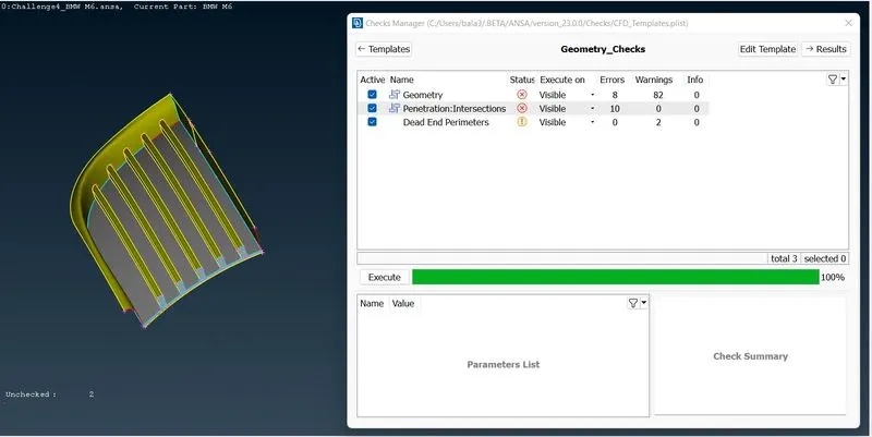
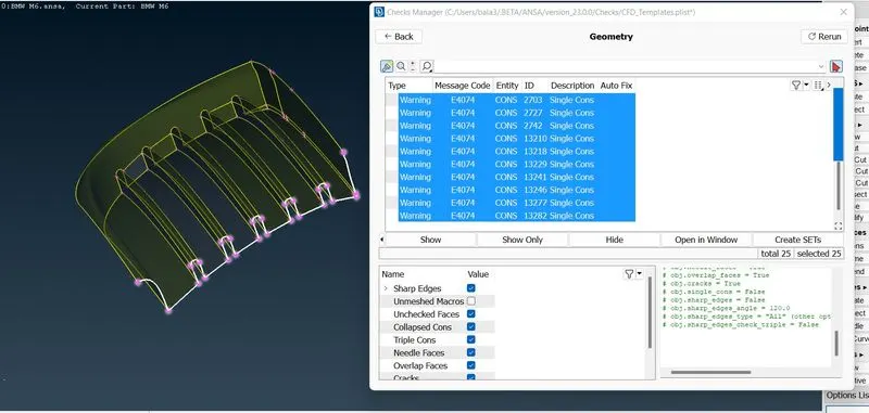
- To clearing all the errors in this particular geometry we have to use the Hot Points --------> Parametrical option to create the hot points with refernce to one hot point with certain percentage. Thus by that on the curved surfaces using this option we can able to create the hot point in its nodes. Then using the Faces --------> Project cut option we can draw the CONS to the newly created hot points to make a cut. Thus by that we can curved cut with reference to the newly created hot points. And then deleting the unnecessary faces considering to make it as a single volume component have to be done.
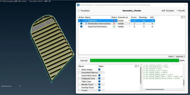
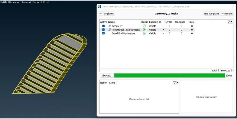
- In this grill one of the particular option used to make it into a single volume is Faces -------> Plane Cut option. The idea is to create a plane with respect to the hot points and to make a cut on the grills. Then the unneeded faces have to be deleted to make it as a single volume. Then as normal the new hot points is created at the required faces by Hot points -------> Insert option. Then with respect to the hot points new faces are created using Faces --------->New option,
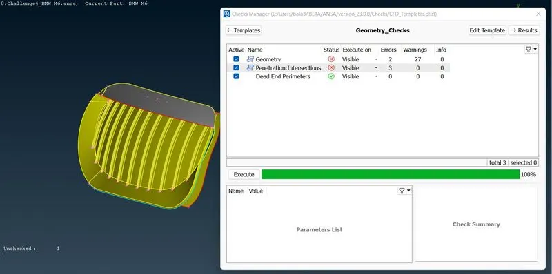
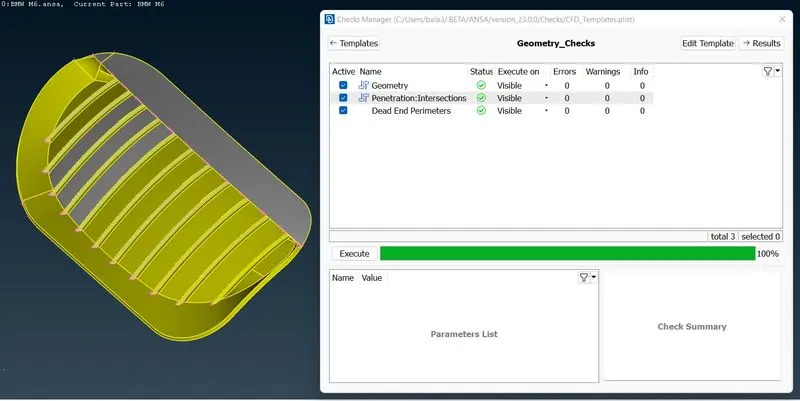
- In the below given images, left is the model that we got having more intersecting errors. So we have to clear it. For doing that we can delete the bottom surfaces that are intersect with each other and have to create a new faces there. For that we need a reference curve at the outer line. So we use Curves ---------> Cons2Curves option to draw the curve on the top of the cons. Thus by that if we are deleting the faces the curves will remain the guiding curve for us to create new faces. In the right I added the images with no error and clear bottom surfaces.
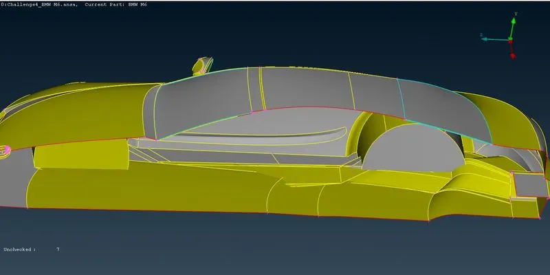
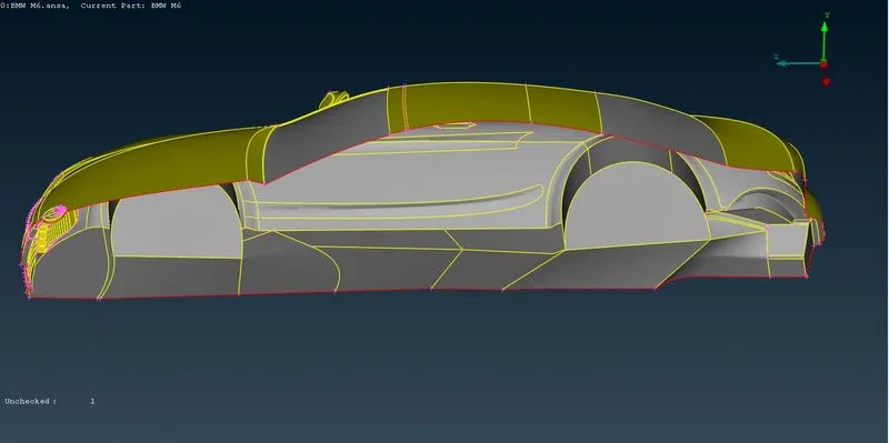
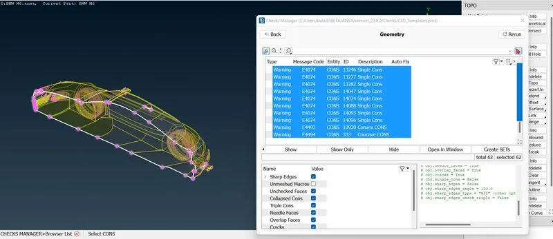
- Thus by viewing each and every part of the assembly, we cleared all the errors in the geometry. Hereby I attached the piture of the geometry with all the errors cleared except the single CONS on the one side of the chassis, where we have to build the symmetrical one.
3. Assigning PID:
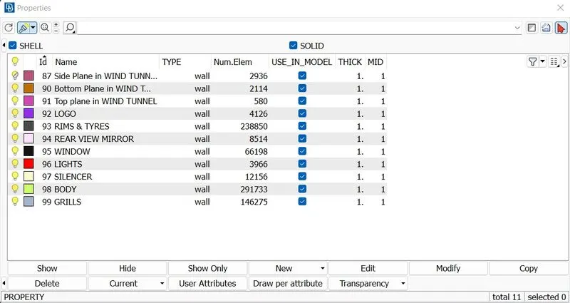
After clearing all the error we have to assign the PID to the component as given in the project respectively. To assign the PID we have to go to Faces ---------> Set PID option. By the selection of each option we have to assign new PID using the respective name as like the image attached below.
4. Surface Meshing:
After that we have to go for the Classic Mesh Option for doint the surface meshing of the assembly with respective to the Data given in the project. Here in this project we are using the Auto CFD option for all the meshing.
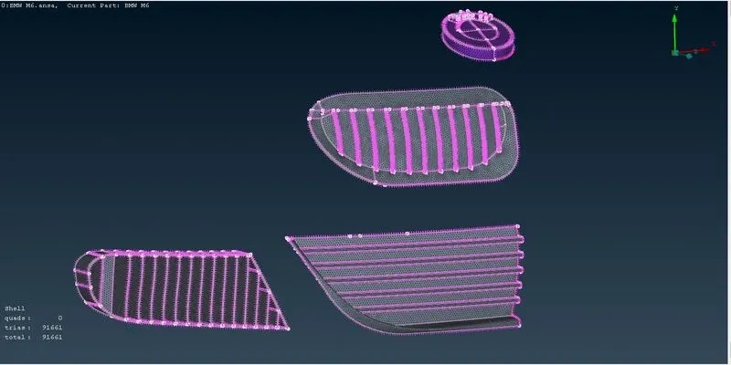
After doing meshing for the each target length we have to freeze the macros within it. For that we have to use the Macros ---------> Freeze/Unfreeze option. We can freeze the macro by left click in the mouse and to unfreeze we have to use the Right click.
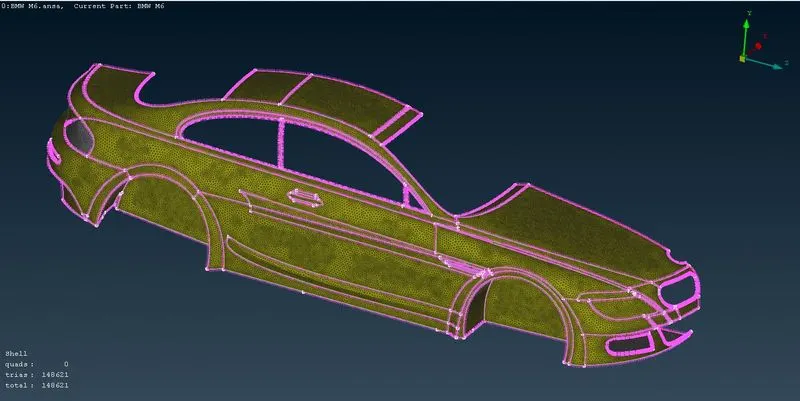
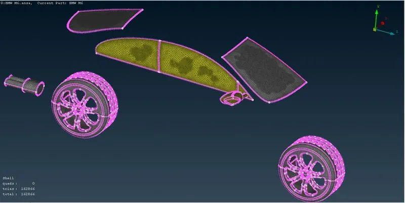
5. Quality Criteria:
Quality criteria is used to check whether the defined target length, characteristics will get achieve in our meshing or not. We have to predefine the each value in the Quality criteria depending upon the geometry requirment. For Ex. Here we gave Skewness Value as 0.5, Minimum length as 0.2mm and Max length as 6mm. If the created macros doesnot suit for this criteria Off elements will occured. And we can see the variation with respect to the color code provided for the quality criteria. To go for the further step we have to remove all the Off elements in the geometry. For doing that, we have to go for Improve ---------> Reconstruct, Reshape, Smooth and Fix quality option. For getting these options we have to right click on the off elements.
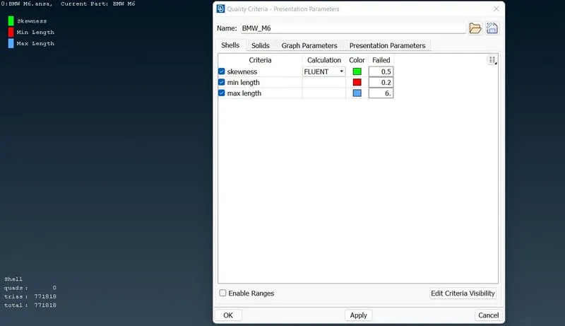
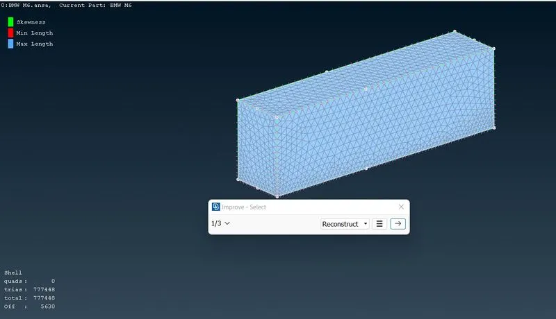
By doing the improve option ANSA will automatically clear the Off elements by doing the corrections what we suggested. But at some times after trying all these option in improve, still some off elements are pending. For that we have to remove the off elements manually by the option Grids -------> Move option. By using this option we can alter the node of the macros by understanding what to change.
6. Creating a full body by Symmetry:
For the creation of full body of the assembly from its half we have to go for the Transforms -------> Symmetry ------- Three points plane option. By selecting this option we have to select the three points in the one portion of the assembly to mirror it..
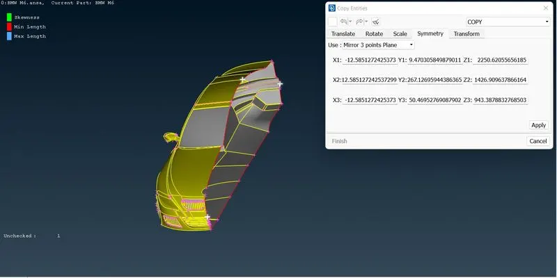
After selecting like the above attached image, if we press okay the total assembly will come.
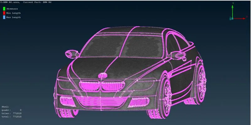
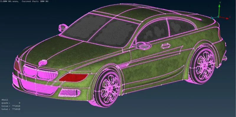
After the overall process is done the Total elements in the assembly is 7,71,818.
8. Creation of Wind Tunnel:
So as our aim of the project is to do the external flow analysis in the BMW, we have to create the Wind tunnel for performing those operation. For creating a wind tunnel, we are having the particular length for creating the wind tunnel. The Front face of the wind tunnel from the extreme front part of the car is 4X, where X is the overall length of the car. Then the Top face of the wind tunnel from the extreme top part of the car is 3X. The rear face of the wind tunnel from the extreme rear part of the car is 6X. There is no such requirement for the bottom plane of the wind tunnel. Either it can on the bottom surface of the part or leviated at certain height that purely depends upon which analysis we are going for.
So initially for doing that we have to insert a point , but before that we have to measure the overall length of the car. And then we have to select the one middle point from the center of the car to mark the point in the front and vice versa.
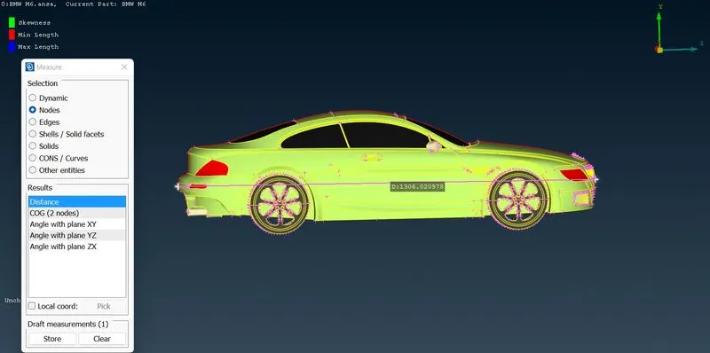
After measurement is done, we have a insert a point using Points --------> New command in the center point of the car. So from the point with respect to the distance required for the front and rear top faces we have to create a point using Points ---------> Relative option. So after drawing all the points for drawing the plane, we have to go for the Curve ---------> Create option to create the curve with respect to the points drawn.
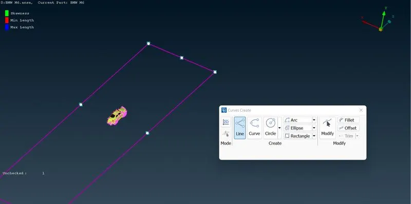
Then we can create the face using the curve created. Thus the bottom face is created. So with respect to the bottom face we can create the side face by offset option. For that we have to go for Faces ---------> Offset option, then we have to mention the offset distance to create a new top face. So after that with reference to these two faces we can create the side faces.
9. Meshing of Wind Tunnel:
For meshing the wind tunnel, we are going to mesh the bottom and top surface with varying target length. And for the side faces we have to mesh it in a incremental order from the bottom face target length to the top face target length.
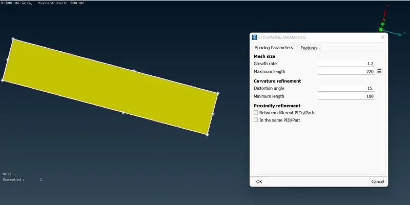
Here I chose the 200mm as the bottom face target length and 400 as the top face target length as that much the computing capability my system had. So after done with the meshing of the bottom and top face of the wind tunnel, here we came to the side meshing ie., Incremental meshing.
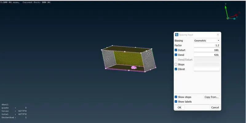
For doing that we just want to go for the Perimeter ---------> Spacing option, and in the dialog box it will ask for the valu of D strat and D end. So we have to provide the value for the incremental meshing. The incremental value will be depend upon the Factor mentioned in the dialog box. After that we have to select the cons of the all the side faces. It will shown us in arrow of growing side. By carefully selecting that we have to apply it. Then we can achieve the incremental meshing in side faces. Thus the wind tunnel is created and meshed.
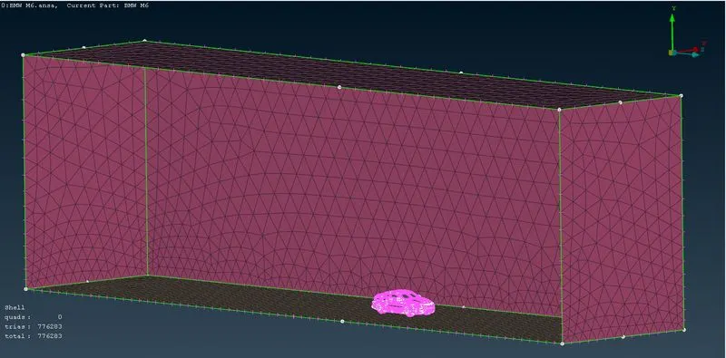
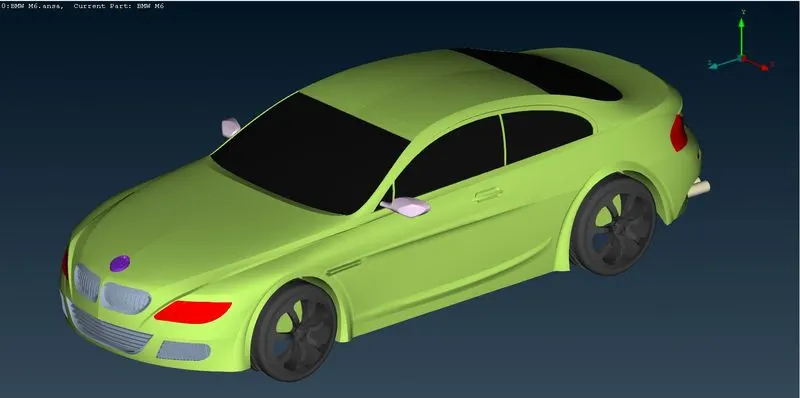
Hereby I added some of the images of the model.
Result:
Thus by that with the given BMW-M6 geometry, we cleared all the geometric and intersection erros and assign the PID for the each and every component. And then the surface meshing is done and also the windtunnel is created.These all are done with the mind of External Flow analysis.
https://drive.google.com/drive/folders/1K0R8OUo7E-Kg-06fEGTV-rmOy3bDkpw_?usp=share_link
Learning Outcomes:
Thus by proceeding the project we get to know how the External Flow Analysis of a car model have to be done and what are the criteria to meet out to achieve the better results.