Week 4 Challenge : CFD Meshing for BMW car
1. Introduction
The main objective of the challenge is to perform a Topology Cleanup and mesh the given geometry of a BMW Car with different mesh length elements to understand the variation in the mesh lengths and Further a Wind tunnel is to be created around the geometry which is to be forwarded for physics simulations. Below are the required Target Lengths for different PID Regions that are to be assigned and Mesh is to be created based on that.
- Body - 3 mm
- Lights - 4 mm
- Grills - 1 mm
- Rims and Tyres - 2 mm
- Optical Rear view mirror - 2 mm
- Window - 2 mm
- Silencer - 3 mm
- Logo - 1 mm
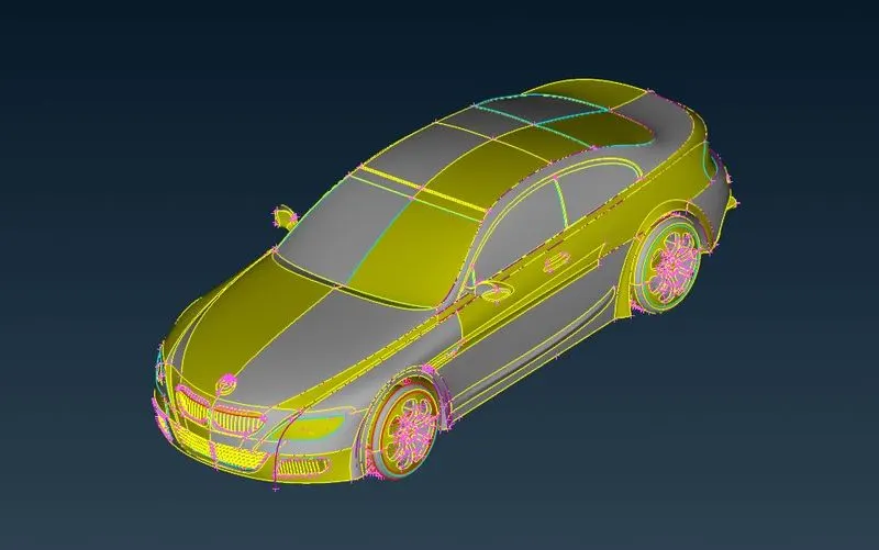
2. Clean-up of Geometry
For any geometry before meshing, it is necessary to be cleaned up with its topology in-order to obtain a good surface mesh used for analysis. Since this is a complex geometry to clean up which leads to a lot of time taking up it, this is to be symmetrically cut and clean up the remaining half. This will further be explained by parts for the topology clean-up.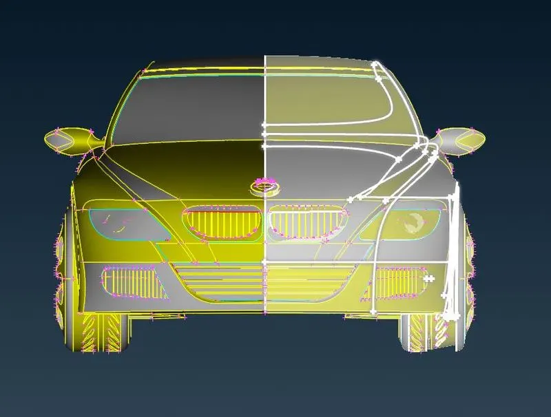
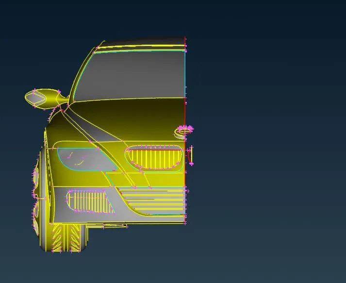
2.1 Bottom Grill
- In this geometry, there are observed to be a lot of unnecessary surfaces which needs to be deleted.
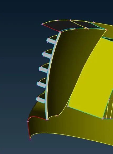
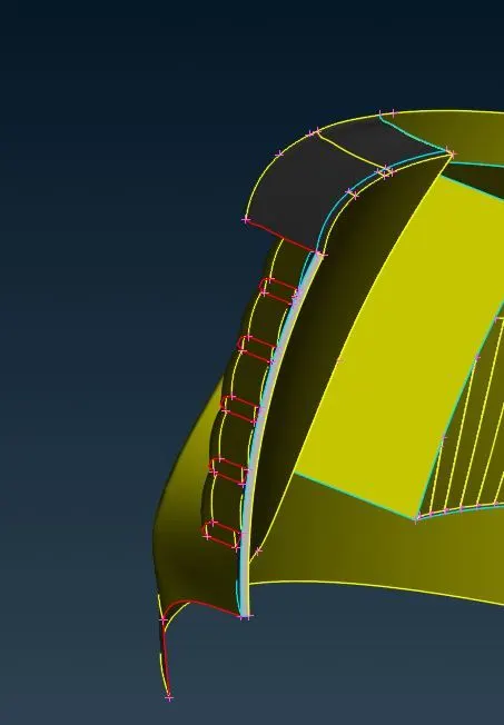
- For doing this, a Project tool has been utilised to projecting the Hot Points onto the required surface.
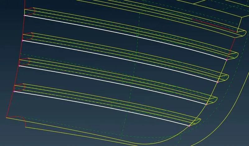
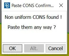
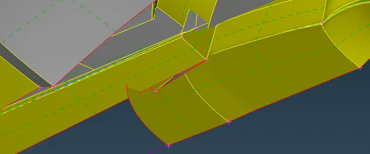
- For the projected points to forming double cons, new surfaces are to be created to join them. In the NEW section, COONS option is selected to form these new faces as represented in the image below.
- After joining all the Hot points, there are still some unjointed edges to be found. These can be joined by using the EXTEND option from the FACES section. This will be done as shown in the representation below.
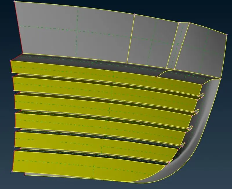
2.2 Side Grill
- First, all the unwanted surfaces are deleted resulting in formation of some Single Cons which will further be joined by using NEW option.
- It can be observed with the grills that there are a few gaps with the grills which needs to be set up to get proper surface for the formation of a common volume. CUT option is used in-order to delete some unnecessary surfaces which could interfere with the formation of uneven surfaces with the new surfaces. This is a below.
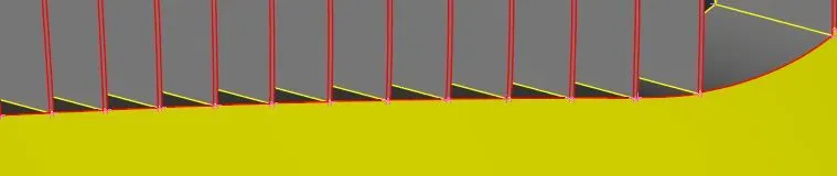
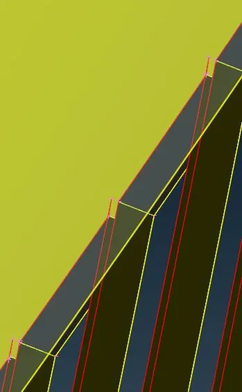
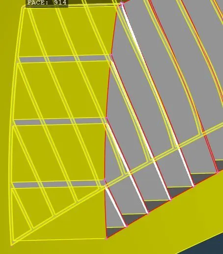
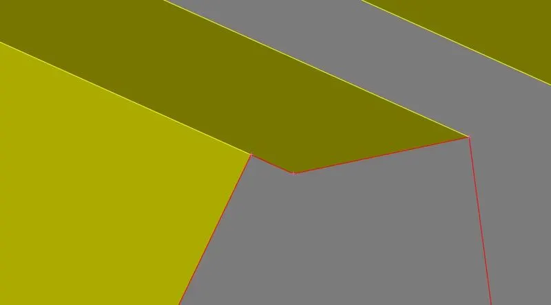
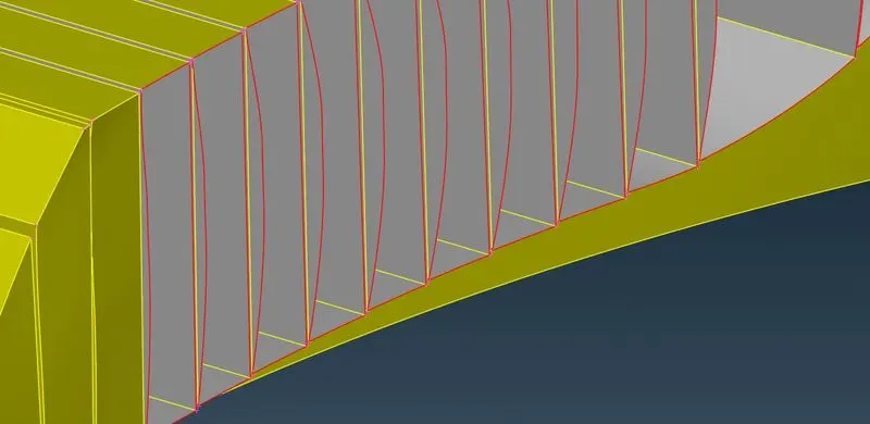
- Further FILL HOLES and NEW option has been used in-order to form these surfaces which converts these Single Cons to Double Cons.
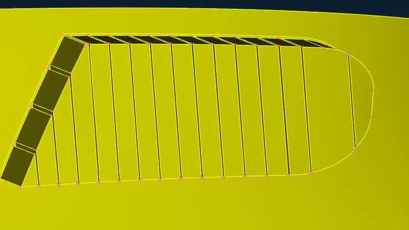
2.3 Logo
- For the Logo seems to have some complex surfaces that needs to be cleaned up by deleting some unnecessary surfaces leading to forming Single Cons.
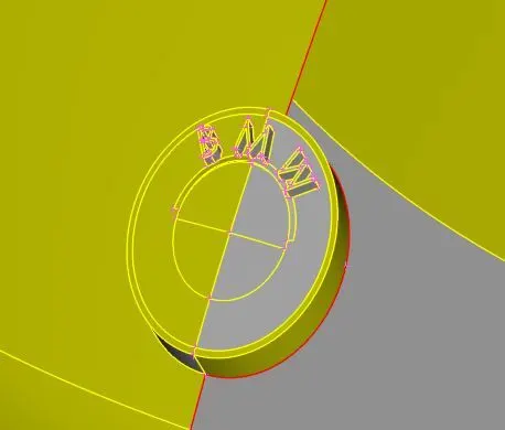
- These single cons are then converted to Double Cons by creating new faces. This is as represented below.
2.4 Upper Grill
- In this geometry, there are observed to be a lot of unnecessary surfaces which needs to be deleted.
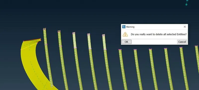
- For doing this, a Project tool has been utilised to projecting the Hot Points onto the required surface.
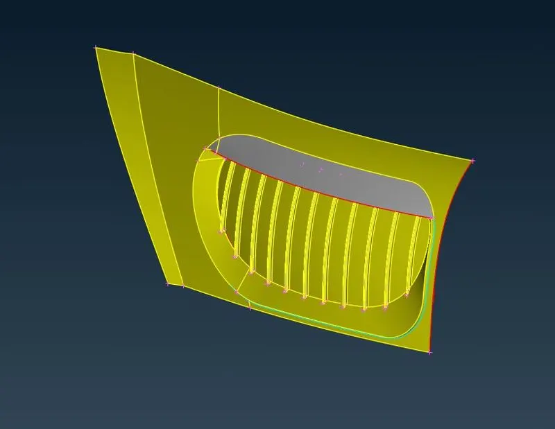
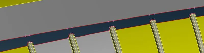
- For the projected points to forming double cons, new surfaces are to be created to join them. In the NEW section, COONS option is selected to form these new faces as represented in the image below.
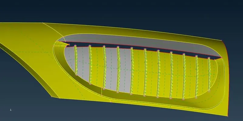
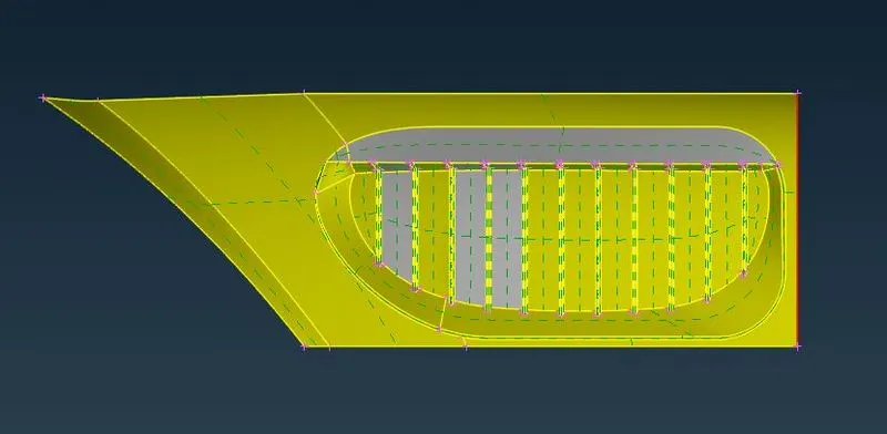
- After joining all the Hot points, there are still some unjointed edges to be found. These can be joined by using the EXTEND option from the FACES section. This will be done as shown in the representation below.
2.5 Door Side Feature
- In this geometry, there are observed to be a lot of unnecessary surfaces which needs to be deleted.
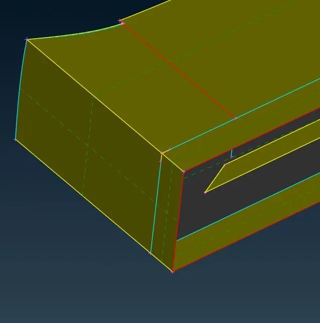
- Some surfaces are observed to be intersecting with each other. To solve this issue, the INTERSECT option is utilized. Upon using this option, these intersecting faces are selected and the unnecessary faces are deleted.
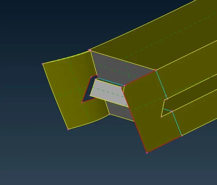
- After joining all the Hot points, there are still some unjointed edges to be found. These can be joined by using the EXTEND option from the FACES section. This will be done as shown in the representation below.
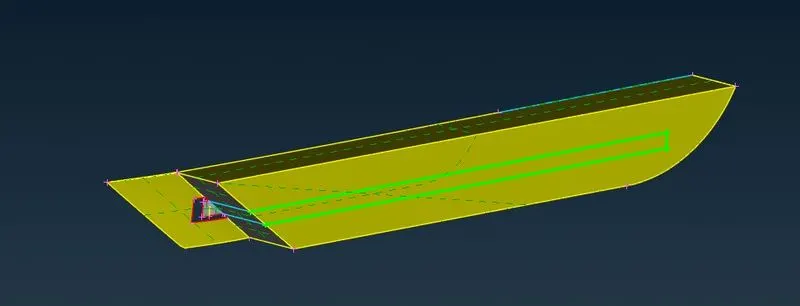
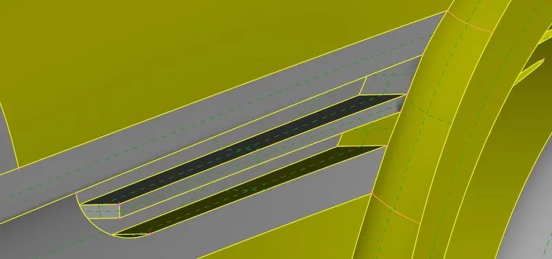
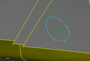
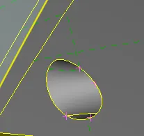
2.6 Mirror
- In this geometry, there are observed to be a lot of unnecessary surfaces which needs to be deleted.
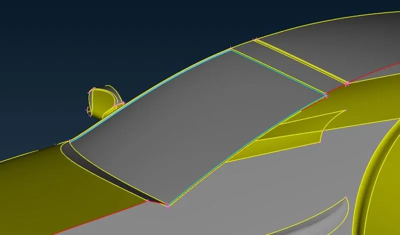
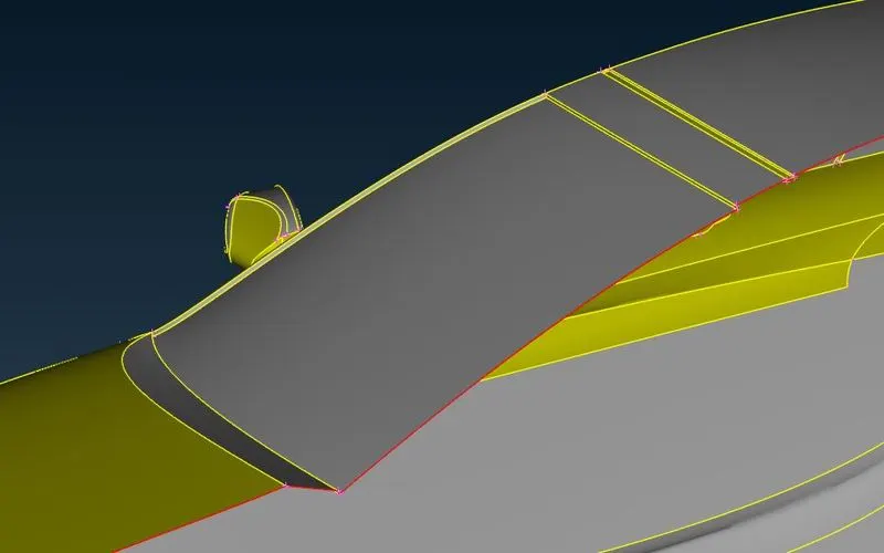
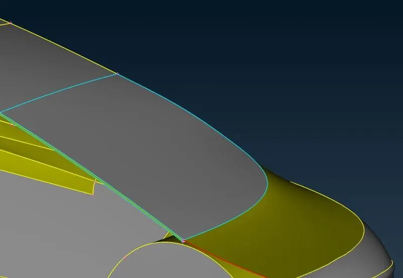
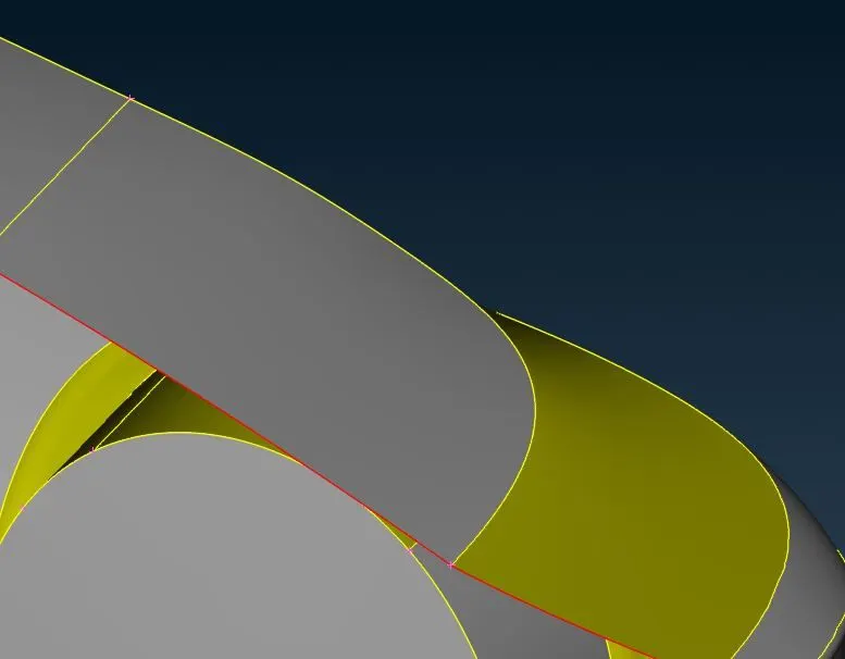
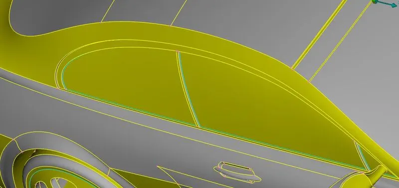
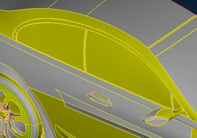
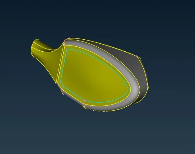
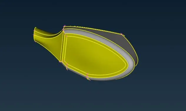
- After joining all the Hot points, there are still some unjointed edges to be found. These can be joined by using the EXTEND option from the FACES section. This will be done as shown in the representation below.
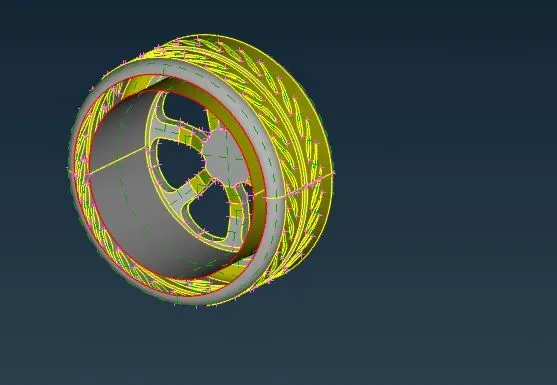
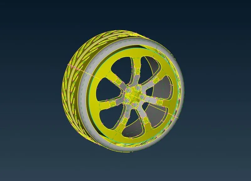
2.7 Tires
- In this geometry, there are observed to be a lot of unnecessary surfaces which needs to be deleted.
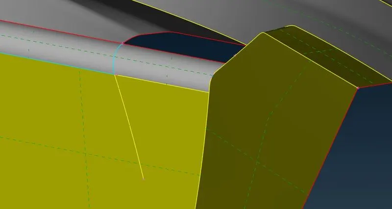
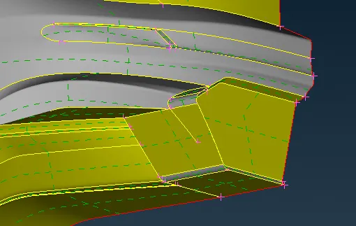
2.8 Body Rear
- In this geometry, there are observed to be a lot of unnecessary surfaces which needs to be deleted and unnecessary cons are cut using the CUT option.
2.9 Body Floor
- In this geometry, there are observed to be a lot of unnecessary surfaces which needs to be deleted.
- Some surfaces are observed to be intersecting with each other. To solve this issue, the INTERSECT option is utilized. Upon using this option, these intersecting faces are selected and the unnecessary faces are deleted.
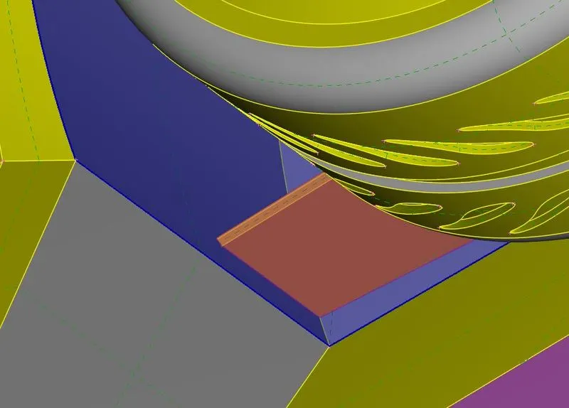
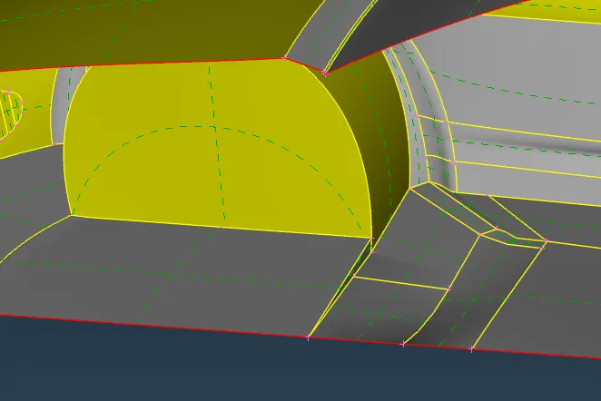
- To retain some of the details in-orer for the surface creation further, CURVES tool is utilised which is as represented below.
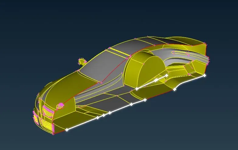
- For the projected points to forming double cons, new surfaces are to be created to join them. In the NEW section, COONS option is selected to form these new faces as represented in the image below.
3. PID Assignment
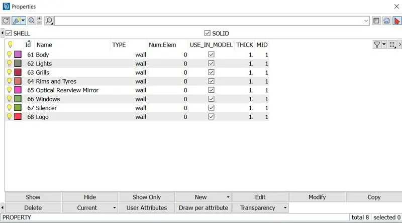
It can be observed from the Properties section is that there are a lot of PIDs assigned for all the surfaces which needs to be assigned together which will be helpful to assign the different Mesh lengths in further sections.
- A right click in the properties window and clicking on the NEW option creates new PID which can be renamed as per the requirement.
- Based on the new PIDs created and named according to the parts, right clicking on the PID and clicking on the Apply will help in getting the selected PIDs to be applied to the new PID as represented below.
4. Meshing the geometry
Meshing different parts of the geometry as per there minimum lengths which could be determined using the MEASURE tool. Based on these minimum values, the Minimum, Maximum a Target Length values are to be setup. The Target Length values are as mentioned below.
- Body - 3 mm
- Lights - 4 mm
- Grills - 1 mm
- Rims and Tyres - 2 mm
- Optical Rear-view Mirror - 2 mm
- Window - 2 mm
- Silencer - 3 mm
- Logo - 1 mm
The Meshing of different parts of the body will be explained as individually.
4.1 Logo
- Quality Criteria and Mesh Parameters are setup using these values.
Target Length – 1 mm
Minimum Target Length – 0.4 mm
Maximum Target Length – 2 mm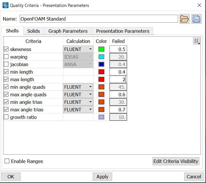
- LENGTH option is used to assign the target lengths to the geometry for both Perimeter and Macros with the same Target Length.
- The geometry is to be meshed by using the SPOT MESH option and selecting the VISIBLE it to get the Mesh for the geometry.
- Now the HIDDEN tool is used to check for the Off Elements which can be resolved using a RECONSTRUCT option in the SHELL MESH Section.
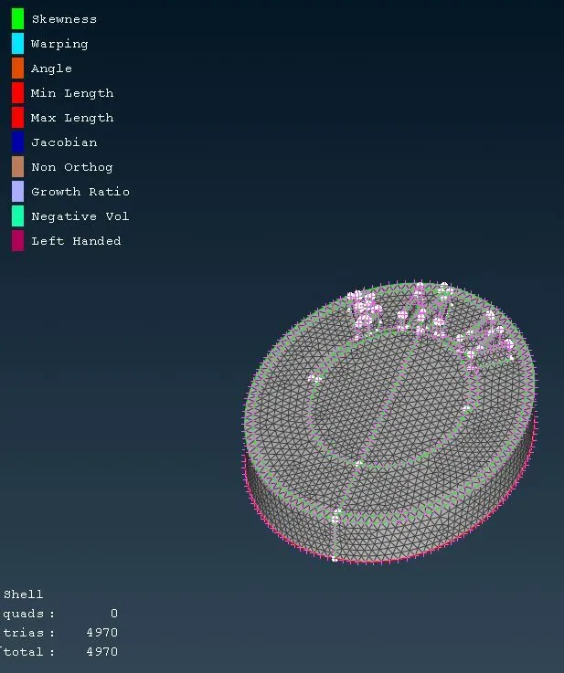
- If this option doesn’t seem to resolve the issues, the below options are used in order to get the Off elements resolved. It is as mentioned below like SMOOTH, SPLIT and MOVE.
SPLIT – This option helps in splitting the edges of an element resulting in formation of more elements.
MOVE – The MOVE option is used to manually adjust the nodes of the element.
4.2 Grills
- Quality Criteria and Mesh Parameters are setup using these values.
Target Length – 1 mm
Minimum Target Length – 0.3 mm
Maximum Target Length – 2 mm - LENGTH option is used to assign the target lengths to the geometry for both Perimeter and Macros with the same Target Length.
- The geometry is to be meshed by using the SPOT MESH option and selecting the VISIBLE it to get the Mesh for the geometry.
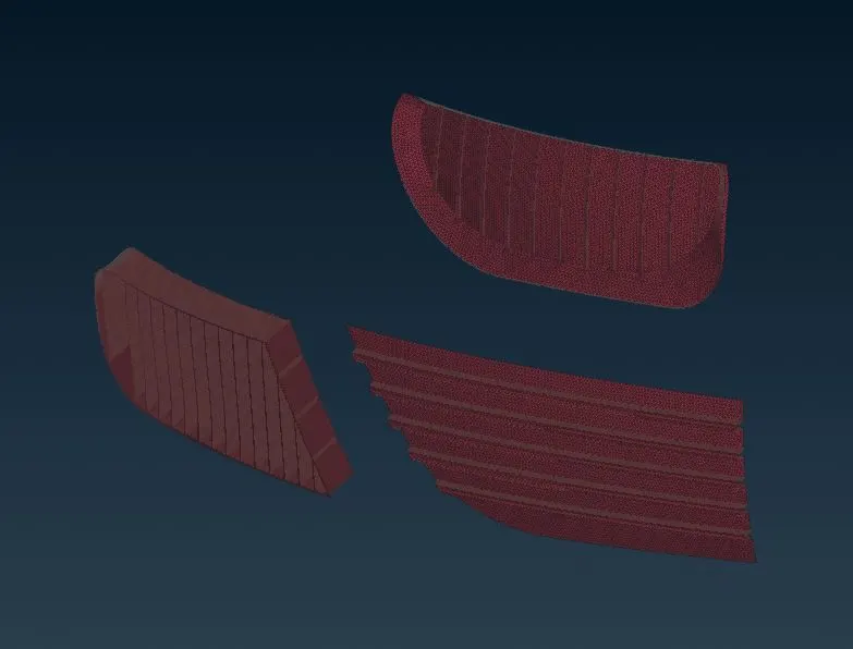
- Now the HIDDEN tool is used to check for the Off Elements which can be resolved using a RECONSTRUCT option in the SHELL MESH Section.
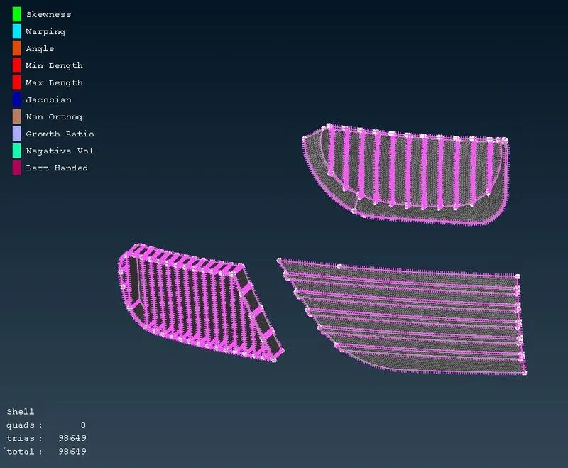
- If this option doesn’t seem to resolve the issues, the below options are used in order to get the Off elements resolved. It is as mentioned below like SMOOTH, SPLIT and MOVE.
SPLIT – This option helps in splitting the edges of an element resulting in formation of more elements.
MOVE – The MOVE option is used to manually adjust the nodes of the element.
4.3 Windows
- Quality Criteria and Mesh Parameters are setup using these values.
Target Length – 1 mm
Minimum Target Length – 2 mm
Maximum Target Length – 3 mm - LENGTH option is used to assign the target lengths to the geometry for both Perimeter and Macros with the same Target Length.
- The geometry is to be meshed by using the SPOT MESH option and selecting the VISIBLE it to get the Mesh for the geometry.
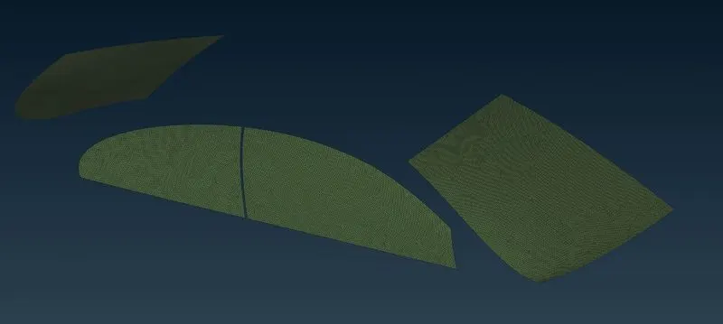
- Now the HIDDEN tool is used to check for the Off Elements which can be resolved using a RECONSTRUCT option in the SHELL MESH Section.
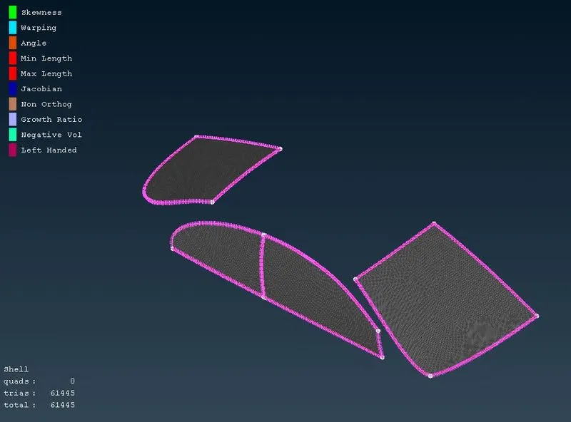
- If this option doesn’t seem to resolve the issues, the below options are used in order to get the Off elements resolved. It is as mentioned below like SMOOTH, SPLIT and MOVE.
SPLIT – This option helps in splitting the edges of an element resulting in formation of more elements.
MOVE – The MOVE option is used to manually adjust the nodes of the element.
4.4 Lights
- Quality Criteria and Mesh Parameters are setup using these values.
Target Length – 4 mm
Minimum Target Length – 3 mm
Maximum Target Length – 5 mm - LENGTH option is used to assign the target lengths to the geometry for both Perimeter and Macros with the same Target Length.
- The geometry is to be meshed by using the SPOT MESH option and selecting the VISIBLE it to get the Mesh for the geometry.
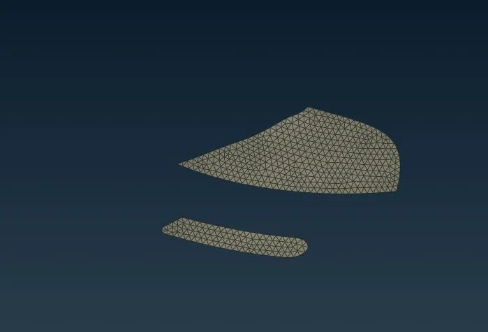
- Now the HIDDEN tool is used to check for the Off Elements which can be resolved using a RECONSTRUCT option in the SHELL MESH Section.
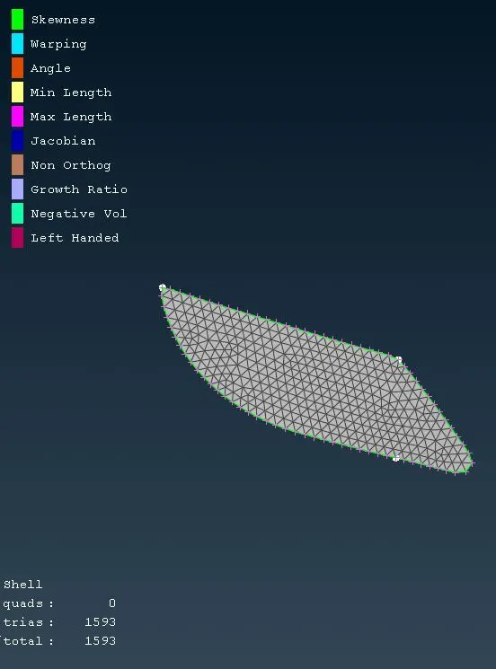
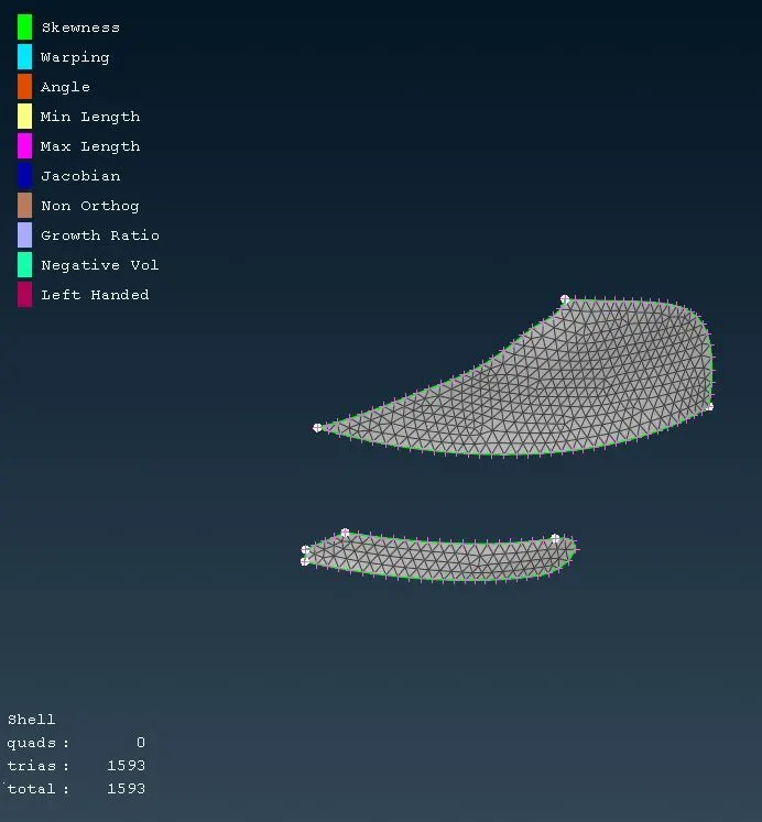
- If this option doesn’t seem to resolve the issues, the below options are used in order to get the Off elements resolved. It is as mentioned below like SMOOTH, SPLIT and MOVE.
SPLIT – This option helps in splitting the edges of an element resulting in formation of more elements.
MOVE – The MOVE option is used to manually adjust the nodes of the element.
4.5 Rims and Tyres
- Quality Criteria and Mesh Parameters are setup using these values.
Target Length – 2 mm
Minimum Target Length – 1 mm
Maximum Target Length – 35 mm - LENGTH option is used to assign the target lengths to the geometry for both Perimeter and Macros with the same Target Length.
- The geometry is to be meshed by using the SPOT MESH option and selecting the VISIBLE it to get the Mesh for the geometry.
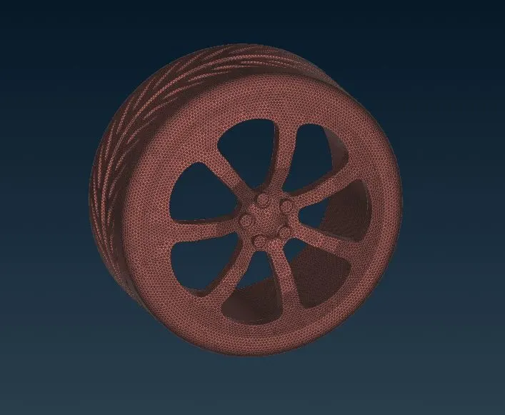
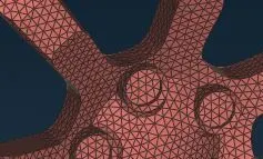
- Now the HIDDEN tool is used to check for the Off Elements which can be resolved using a RECONSTRUCT option in the SHELL MESH Section.
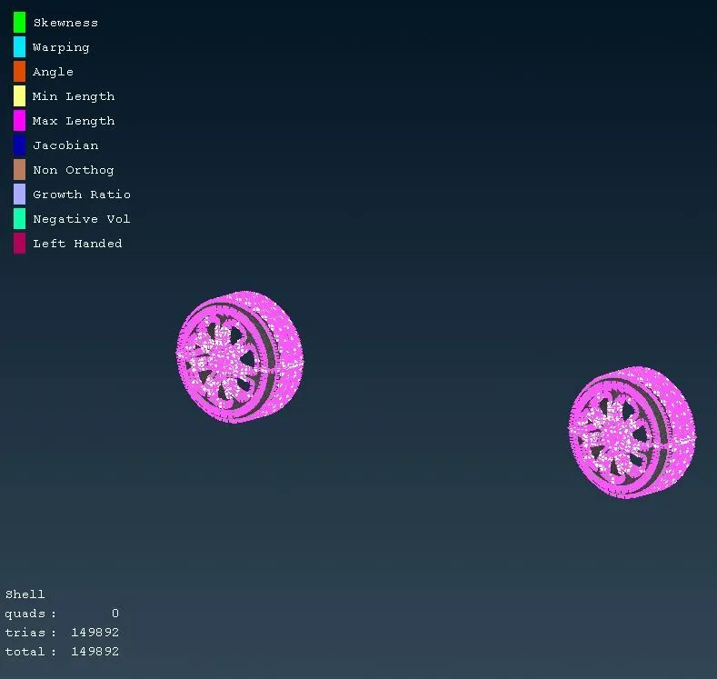
- If this option doesn’t seem to resolve the issues, the below options are used in order to get the Off elements resolved. It is as mentioned below like SMOOTH, SPLIT and MOVE.
SPLIT – This option helps in splitting the edges of an element resulting in formation of more elements.
MOVE – The MOVE option is used to manually adjust the nodes of the element.
4.6 Silencer
- Quality Criteria and Mesh Parameters are setup using these values.
Target Length – 3 mm
Minimum Target Length – 1 mm
Maximum Target Length – 5 mm - LENGTH option is used to assign the target lengths to the geometry for both Perimeter and Macros with the same Target Length.
- The geometry is to be meshed by using the SPOT MESH option and selecting the VISIBLE it to get the Mesh for the geometry.
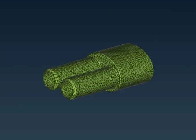
- Now the HIDDEN tool is used to check for the Off Elements which can be resolved using a RECONSTRUCT option in the SHELL MESH Section.
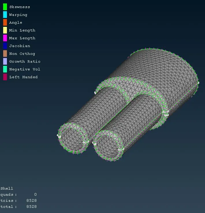
- If this option doesn’t seem to resolve the issues, the below options are used in order to get the Off elements resolved. It is as mentioned below like SMOOTH, SPLIT and MOVE.
SPLIT – This option helps in splitting the edges of an element resulting in formation of more elements.
MOVE – The MOVE option is used to manually adjust the nodes of the element.
4.7 Rear View Mirror
- Quality Criteria and Mesh Parameters are setup using these values.
Target Length – 2 mm
Minimum Target Length – 1 mm
Maximum Target Length – 3 mm - LENGTH option is used to assign the target lengths to the geometry for both Perimeter and Macros with the same Target Length.
- The geometry is to be meshed by using the SPOT MESH option and selecting the VISIBLE it to get the Mesh for the geometry.
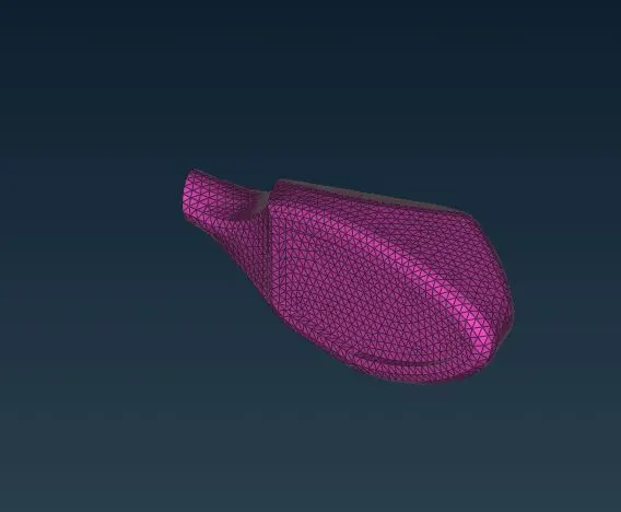
- Now the HIDDEN tool is used to check for the Off Elements which can be resolved using a RECONSTRUCT option in the SHELL MESH Section.
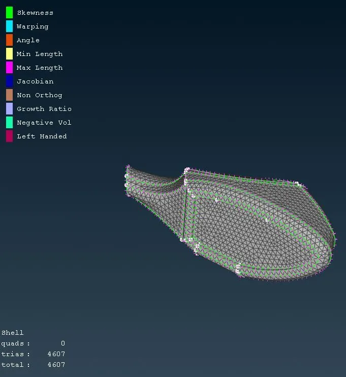
- If this option doesn’t seem to resolve the issues, the below options are used in order to get the Off elements resolved. It is as mentioned below like SMOOTH, SPLIT and MOVE.
SPLIT – This option helps in splitting the edges of an element resulting in formation of more elements.
MOVE – The MOVE option is used to manually adjust the nodes of the element.
4.8 Body
- Quality Criteria and Mesh Parameters are setup using these values.
Target Length – 3 mm
Minimum Target Length – 1 mm
Maximum Target Length – 5 mm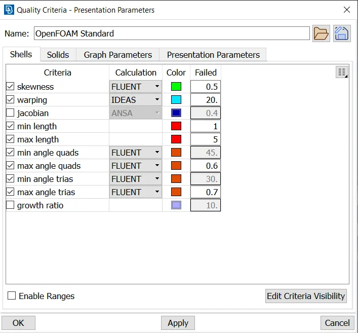
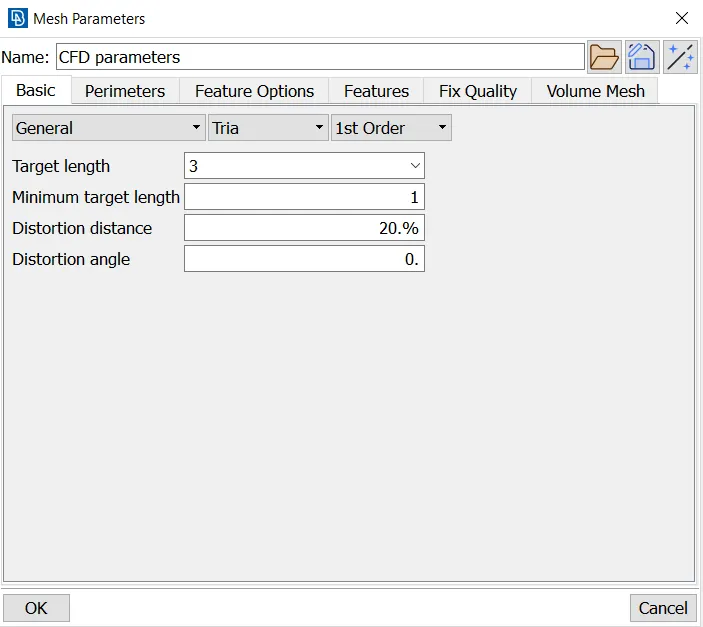
- LENGTH option is used to assign the target lengths to the geometry for both Perimeter and Macros with the same Target Length.
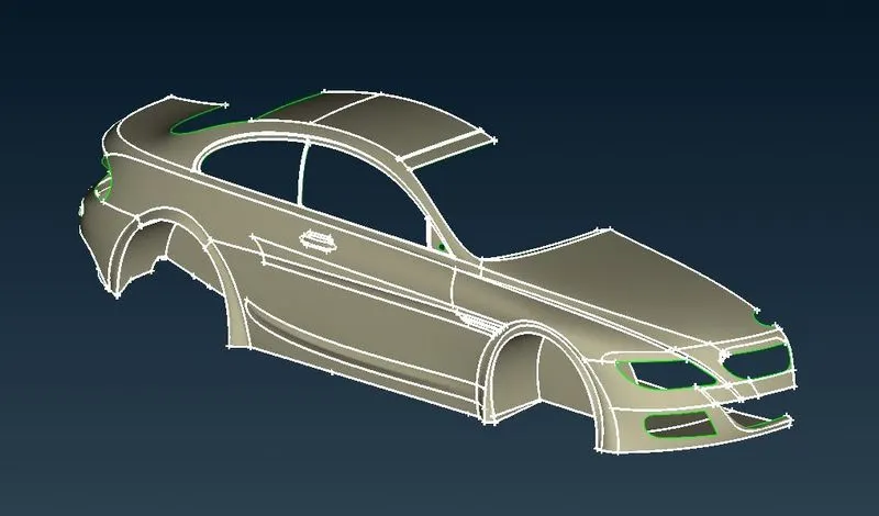
- The geometry is to be meshed by using the SPOT MESH option and selecting the VISIBLE it to get the Mesh for the geometry.
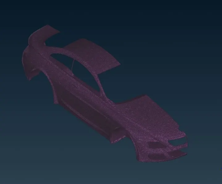
- Now the HIDDEN tool is used to check for the Off Elements which can be resolved using a RECONSTRUCT option in the SHELL MESH Section.
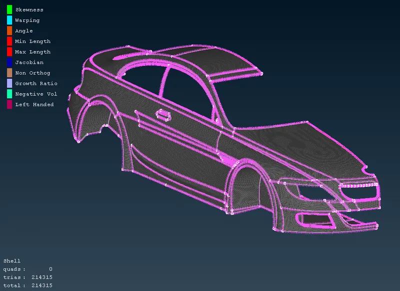
- If this option doesn’t seem to resolve the issues, the below options are used in order to get the Off elements resolved. It is as mentioned below like SMOOTH, SPLIT and MOVE.
SPLIT – This option helps in splitting the edges of an element resulting in formation of more elements.
MOVE – The MOVE option is used to manually adjust the nodes of the element.
5. Symmetry of the Geometry
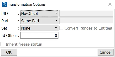
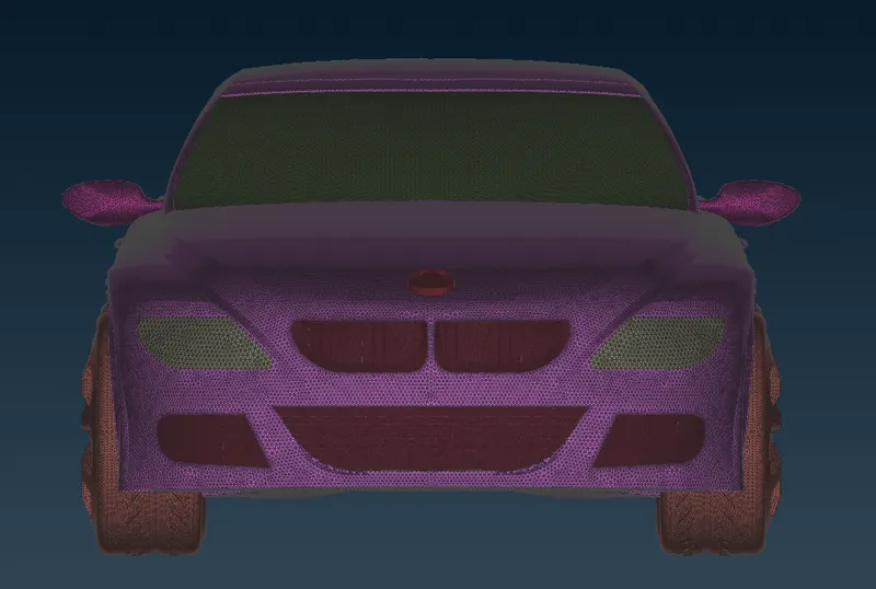
To set the symmetry for the model, a proper view is to be setup in-order to get the output as desired. For this, in the viewport, the TRANSFORM option and then selecting COPY option leading to opening a pop-up window. At this point, the geometry is to be selected except the Logo part. Three points are to be selected on the only remaining Single Con is to be selected as this acts as a plane to get the body symmetry. Middle clicking on it will produce the required symmetrical structure of the geometry as represented below.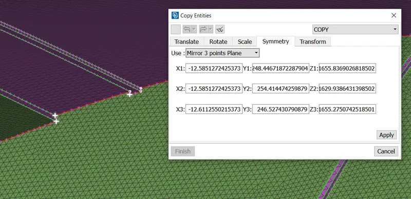
6. Wind Tunnel Creation and Meshing
After the creation of Mesh for all the PID regions, it is necessary to check for any remaining errors which needs to be avoided in-order to avoid its interference in the Surface and Volumetric Mesh. This can be checked by using Geometry Checks and made sure that there are no errors occuring.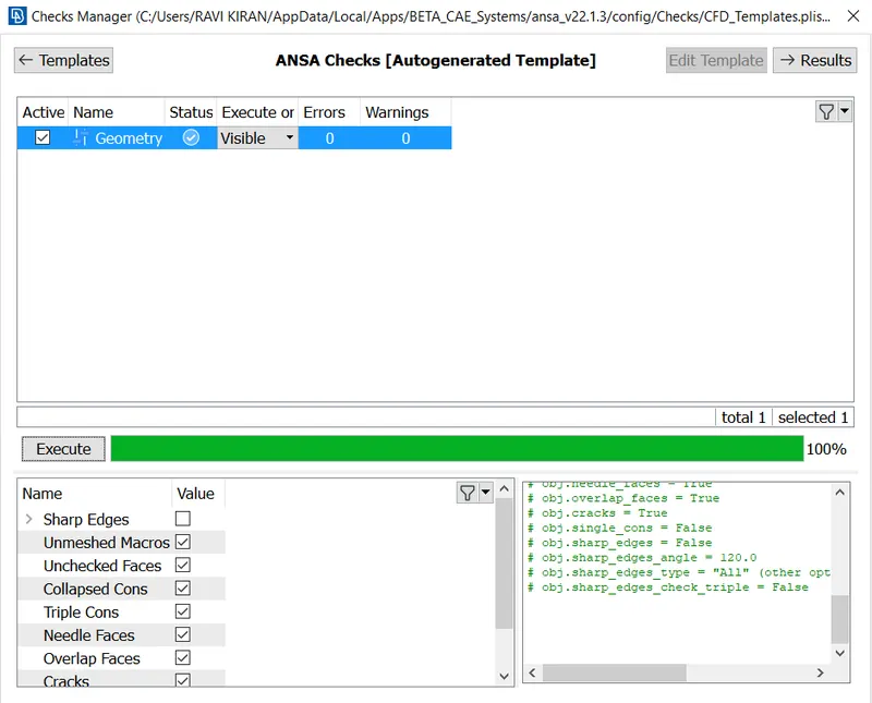
With this, Wind Tunnel Creation and its Meshing process can be initiated.
6.1 Wind Tunnel Creation
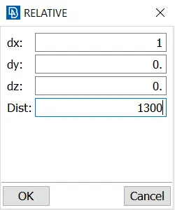
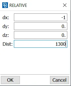
- To create the Wind Tunnel around the geometry, it is necessary to create boundary points first with reference to the geometry. To get these boundary points, RELATIVE option is used from the POINTS section. This option helps in creating a point relative to a selected point in any of the X, Y or Z direction.
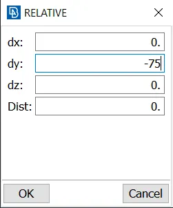
- Upon creation of the first Point asa per the Video references, the remaining Points are to be created based from the first point with the following lengths
Front Point - 5854 mm.
Rear Point - 8410 mm.
Top Point - 3900 mm (from top reference point)
Side Point - 1300 (Both sides of first Point)
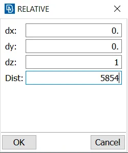
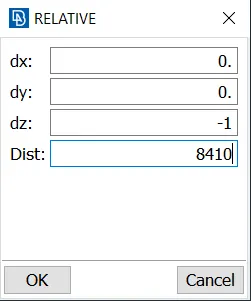
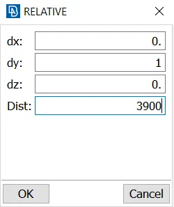

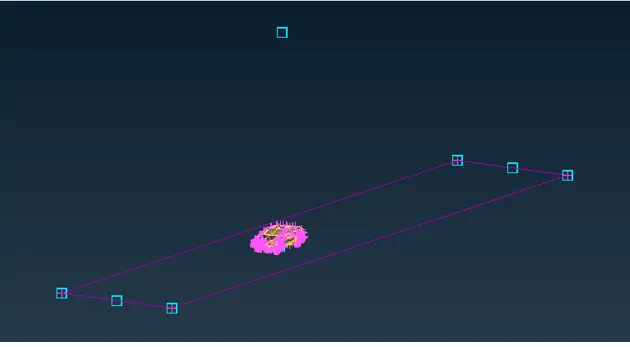
- After creating these reference points, a curve is created joining these points by using the CREATE option in CURVE section as below.
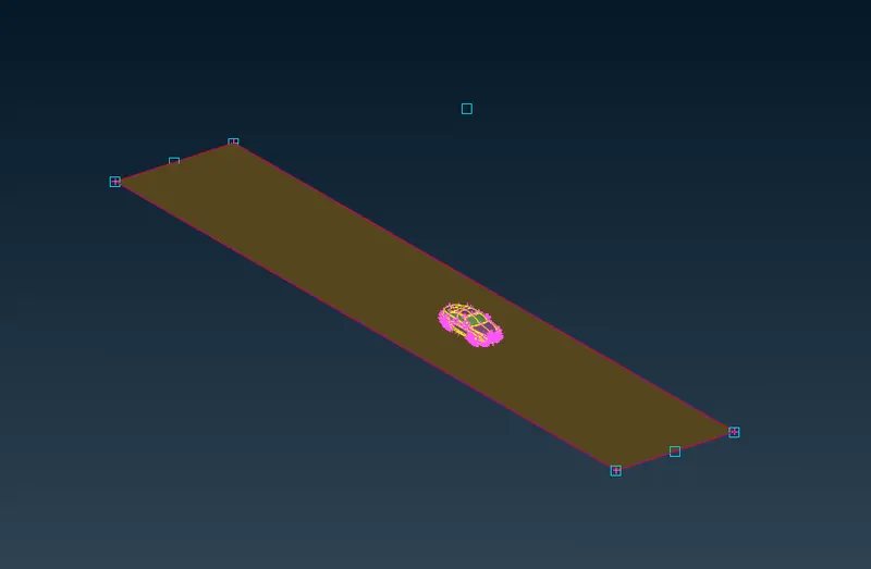
- Upon creating these curves, with its reference, a face is created which will further help in creating other faces of the wind tunnel.
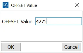
- To create the top face of the wind tunnel, the bottom face created can be utilised for it. This can be done by using the OFFSET option from the FACES section. This can be done by assigning an Offset Value of 4275 mm.
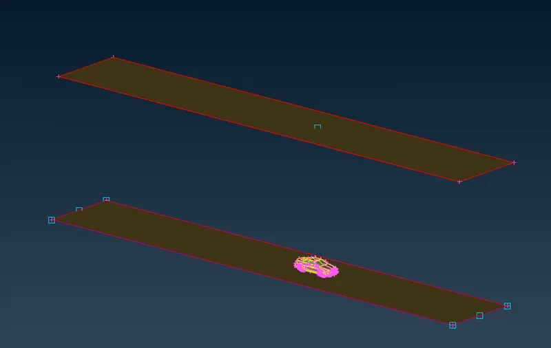
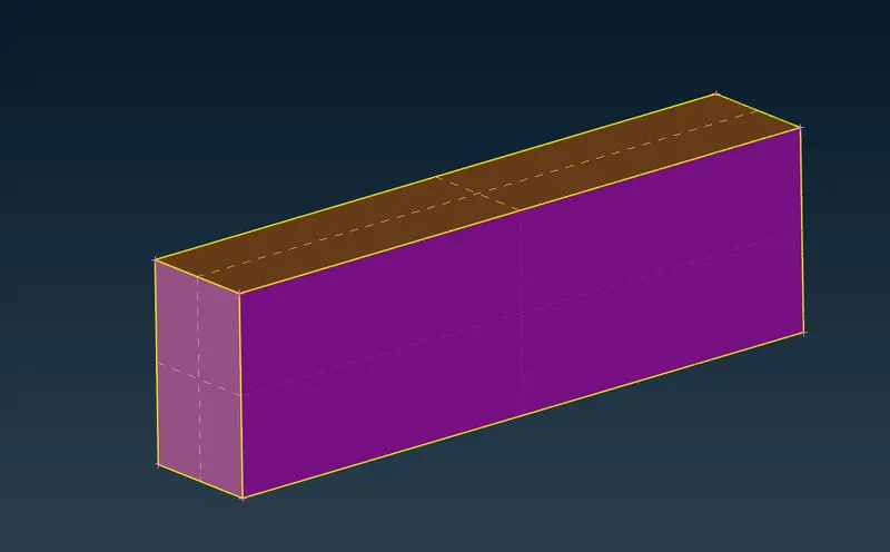
- The other remaining faces can be created using NEW option in the FACES section with reference to the created Base and Top faces as below.
6.2 Wind Tunnel Meshing
-
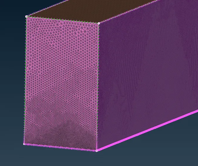
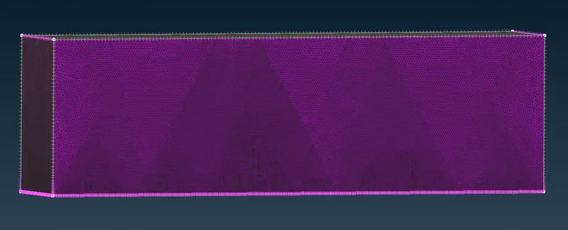
As the Wind Tunnel is created, the next step is to Mesh the Wind Tunnel Surface which further can be utilised for Volumetric Mesh. but in this it can also be observed that the Mesh will become Coarse when the mesh moves away from the main geometry which is expected.
-
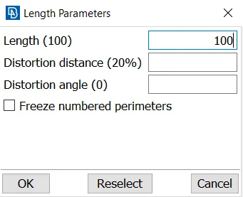
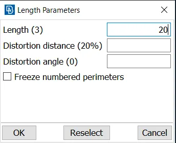
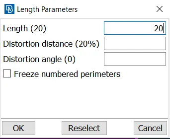
For this particular mesh, the quality criteria of Maximum and Minimum lengths cannot be used. For this, the Mesh lengths mentioned below can be assigned in the Mesh Parameters pop-up window.
Top surface = 100 mm.
Bottom surface = 20 mm.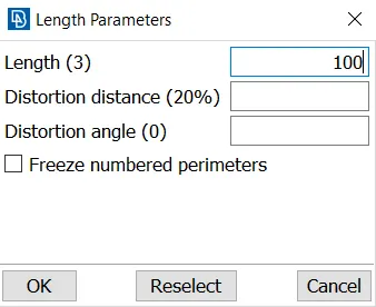
-
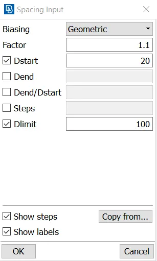
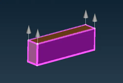
Since the Mesh Lengths for Top and Base faces are different, for the Front, Rear and Side faces, variable mesh length is to be assigned which can be done by using SPACING option from the PERIMETERS section. Required vertical edges of the Wind Tunnel Geometry is to be selected as represented below.
-
Meshing of these unmeshed surfaces is to be done indeviually by using "local" for Target Length since the mesh to be created is variable in this case. The below representation shows the created Surface Mesh for the Wind Tunnel Structure.
- Point to be noted in here is that the Volumetric Mesh has not been performed in this Challenge as it considerably takes longer to complete the mesh. So the Model is being submitted after performing a surface Mesh.
7. Conclusion
The objective of performing a Topology Clean-up and meshing the geometry of a BMW Car with prescribed mesh Target Lengths has been performed and further a Wind tunnel has been created around the geometry which can now be forwarded for physics simulations.
Point to be noted in here is that the Volumetric Mesh has not been performed in this Challenge as it considerably takes longer to complete the mesh. So the Model is being submitted after performing a surface Mesh.
To support the output, below is the Model Link to the output geometry.
Model Link: Challenge - 4: CFD Meshing for BMW car