Week 4 Challenge : CFD Meshing for BMW car
Aim:
To generate surface mesh over the given BMW M6 model.
Objective:
The given model should be cleaned up and different mesh parts should be meshed as per mentioned element size. The entire model should be enclosed inside the enclosure and be considered as wind tunnel.
Wind Tunnel :
Wind tunnels are large tubes with air blowing through them which are used to replicate the interaction between air and an object flying through the air or moving along the ground. Researchers use wind tunnels to learn more about how an object react whhen it comes in contact with the moving fluid. Most of the time, large powerful fans suck air through the tube. The object being tested is held securely inside the tunnel so that it remains stationary. The object can be an aerodynamic test object such as a cylinder or an airfoil, an individual component, a small model of the vehicle, or a full-sized vehicle. The air moving around the stationary object shows what would happen if the object was moving through the air. The motion of the air can be studied in different ways; smoke or dye can be placed in the air and can be seen as it moves around the object. Coloured threads can also be attached to the object to show how the air moves around it. Special instruments can often be used to measure the force of the air exerted against the object.
Procedure:
We import the BMW geometry in ANSA. First we clear the hot points and do TOPO for the entire model. In this model we are required to perform an external flow analysis so, we only do the surface meshing . Therefore we are giving importance only to the external surfaces and edges, we have to retain all edges and curves as it should be while we perform geometry clean-up. We do not want any surface to form volume of its own (closed surfaces) as we need a contnious geometry throughout , as it ensures entire model as a single geometry with no gaps.
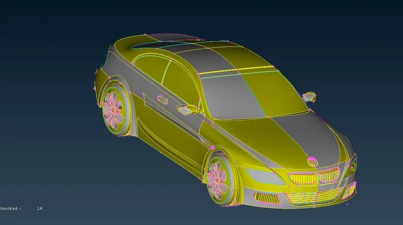
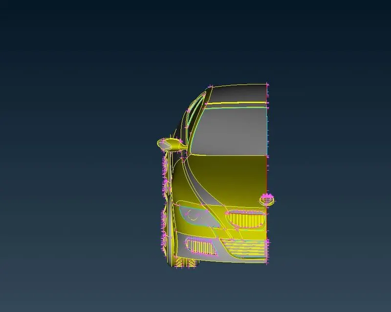
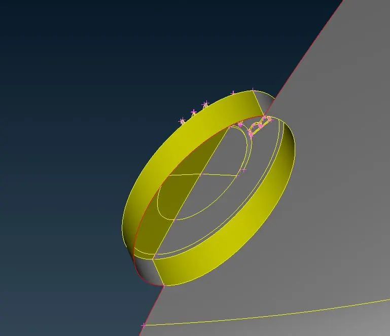
Starting off we disect the model into two half as it is geomentrically symmetry model , we can make it as a complete car once we done cleanup on one of the model. We do this using the universal delete option. We isolate the Logo as it is not symmetry.
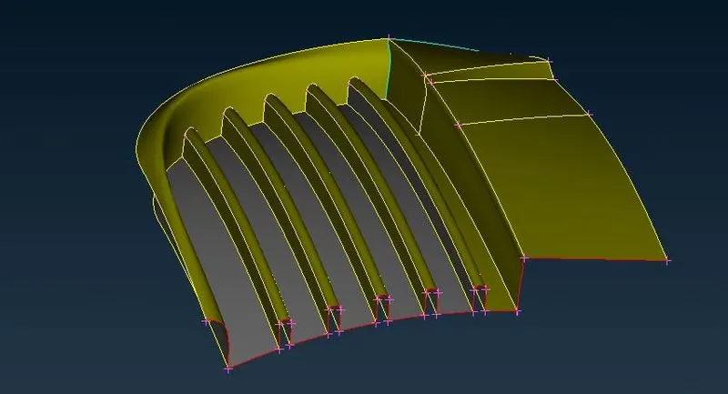
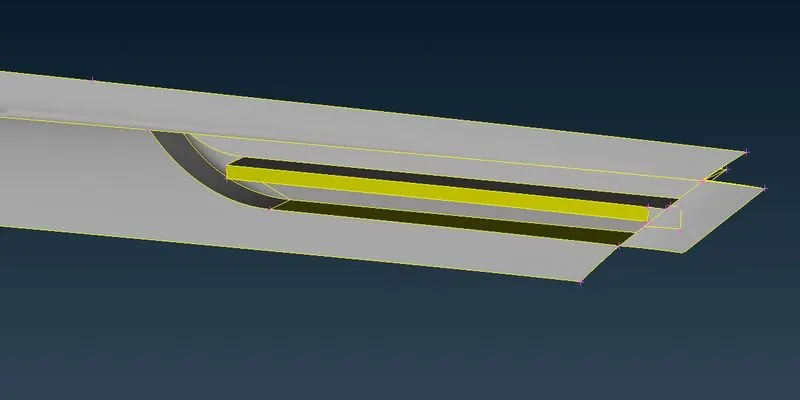
First we do geometry cleanup for the grills. We delete the solid edges in it and make it as a single surface using different faces. We use tools like projection, coons to curves,parametrical, multi project, Extend etc,. to eliminate the single and triple CONS. This process is done individually on each parts, for every part we ensure that the outer surface is retained as such. And for filling single cons with common end poits we use Paste tool to create a surface.
 \
\
After eliminating all the errores, the single CONS only present on the midplane. Next we define the PID's for each part.
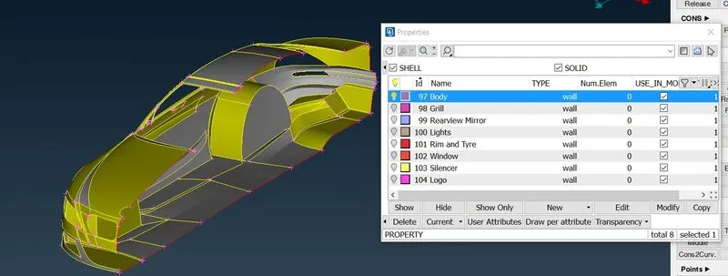
Then we do a geometry check to check for intersection error and single and triple cons. And solve th errors till it is eliminated.
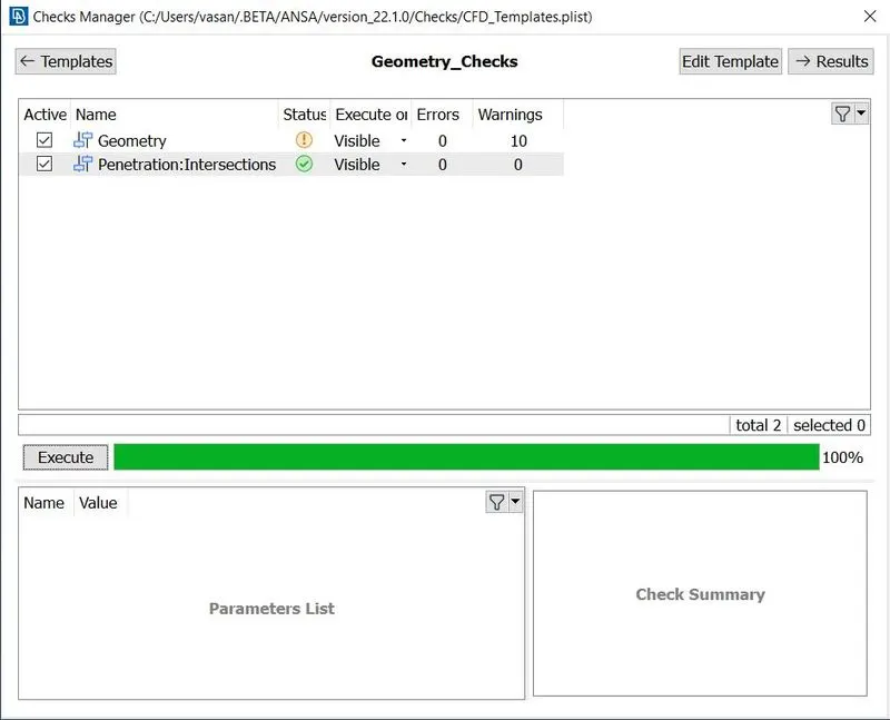
Since there are no errors we proceed to surface meshing for each component with different mesh sizes. Before starting we need to give the inputs for the mesh quality criteria , this is done to check the mesh generated is good enough to produce accurate results during simulation. For this case we define the maximum and minimum lengths with respect to the given mesh sizes,
- Body - 3 mm
- Lights - 4 mm
- Grills - 1 mm
- Rims and Tyres - 2 mm
- Optical Rear view mirror - 2 mm
- Window - 2 mm
- Silencer - 3 mm
- Logo - 1 mm.
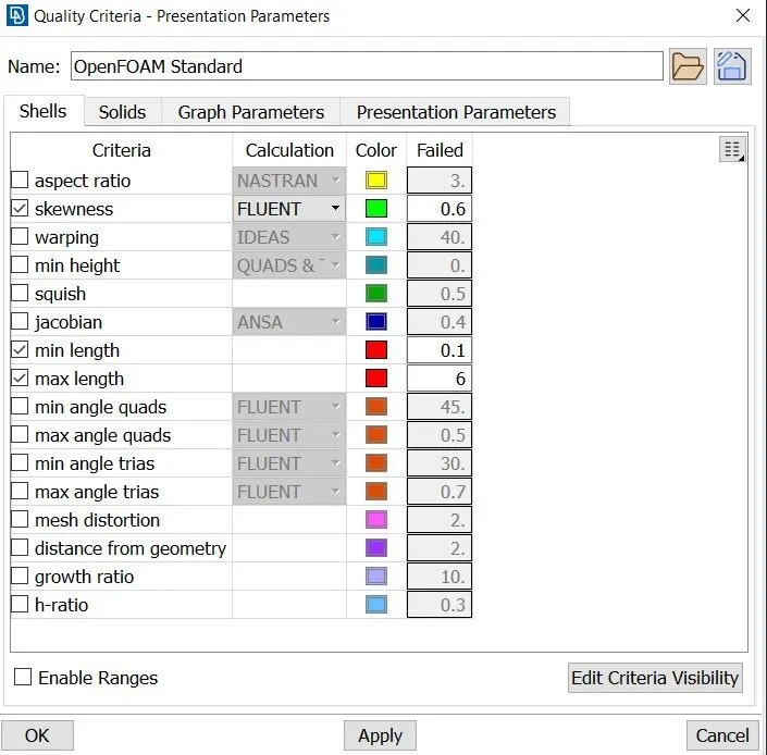
Once we mention the range under mesh mproperties we choose CFD mesh under spacing and select the target PID and define this range for both Perimeter and Macros. Then we do CFD meshing under mesh generation. We repete this process for all PID's. Then to correct the Off elements we do
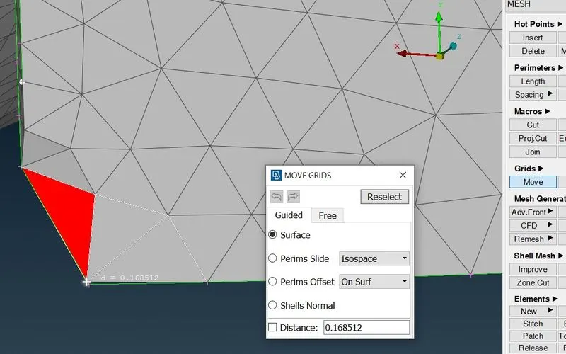
Improve> Reconstruct> Edges > Ok this eliminates most of the off elements. This off elements are elements in mesh which is beyond our mentioned quality criteria. Some elements are to be corrected manually, for this we use the option move under grids.
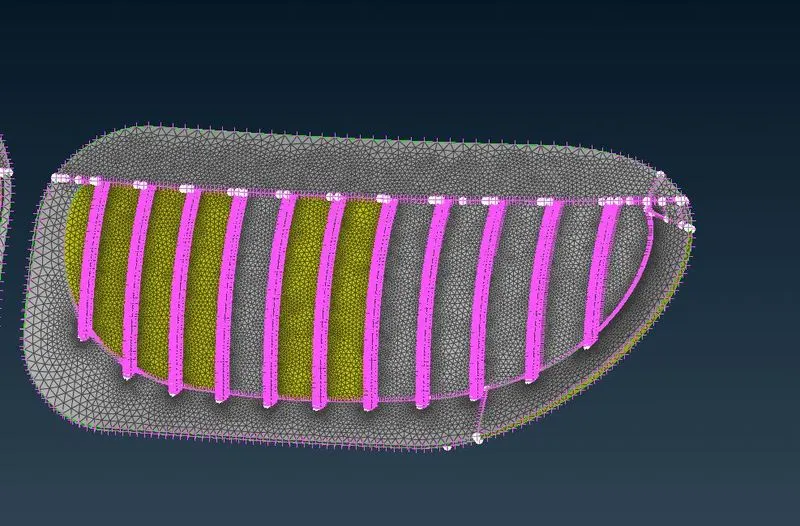
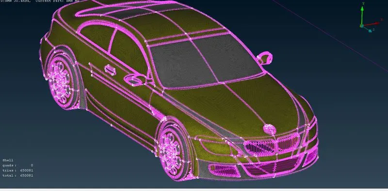
Once all done we have to mirror the half part to generat the complete model. this is done using transform option and selecting points along the mid surface. Next we have to create the enclosure around the model for that we follow the general rule to determine the end points of the domain.
Front : 4*Length of the Car
Rear : 6*Length of the Car
Top : 3*Length of the Car
Side & Bottom : Away from the nearest surface.
We create points using relative tool and with that we define the curves out of which we finally create a surface. For the top face we use offset tool to create a new surface at a distance from the existing surface.
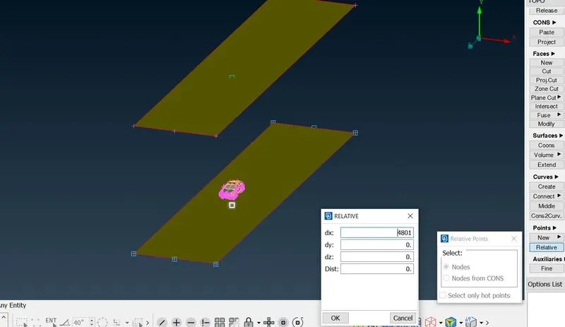
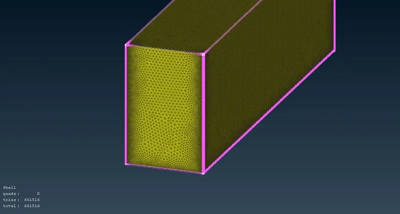
Our aim is to create finer mesh at bottom an as the mesh reacehes top the mesh element size should be bigger than that of bottom. This is done using the manual option under spacing where we give Dstart as 30mm and upper limit as 130 mm with growth rate of 1.2. this way the mesh is generated in a progressive manner.
Conclusion:
In this way the tria elements are created over the surface of the mody and as well as on the enclosure (wind tunnel). The volumetric mesh is not generated because it requires high computational power and time. Thus generation of surface mesh is understood with the addition of quality criteria.
Link : https://drive.google.com/file/d/1yHZrMIpfYR5c8W_l9mx1szvm0hNOWDZO/view?usp=sharing