Week 4 Challenge : CFD Meshing for BMW car
Aim:
- To clean the geometry.
- Mesh the components part by part.
- Eliminate off elements present in the mesh.
- For the given model, check and solve all geometrical errors on half portion and Assign appropriate PIDs. and to perform meshing with the given Target length and element Quality criteria. After meshing the half model, Do symmetry to the other side.
- Target lengths for the different parts of a model are as follow:
- Body - 3 mm
- Lights - 4 mm
- Grills - 1 mm
- Rims and Tyres - 2 mm
- Optical Rear view mirror - 2 mm
- Window - 2 mm
- Silencer - 3 mm
- Logo - 1 mm
Take away:
At the end of this article one will be able to,
- Use different tools to clean the geometry.
- Understand the quality criteria assigned to each and every PID.
PRE CLEAN UP GEOMETRY:
- First we have to upload the geometry.
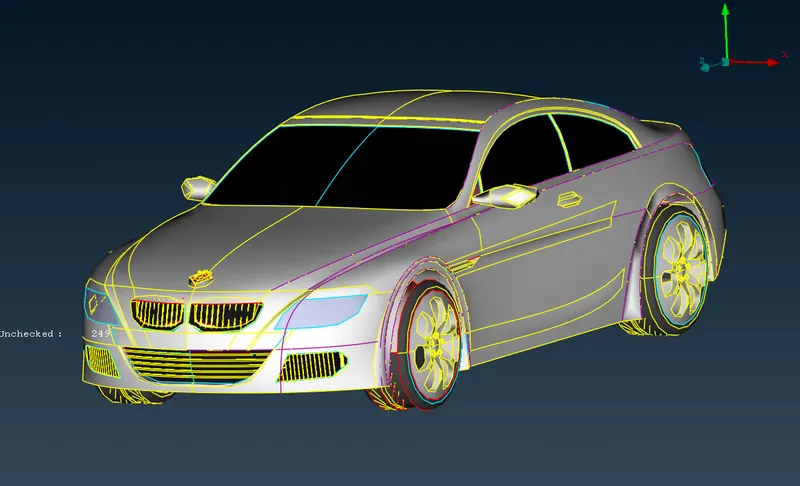
- There are lot of red and blue cons.
- Red cons are edges with one surface attached and blue cons are edges where three surfaces meet.
- So the goal here is to remove red cons and avoid the formation of blue cons.
- This will be done part by part for easy access.
Resolution:
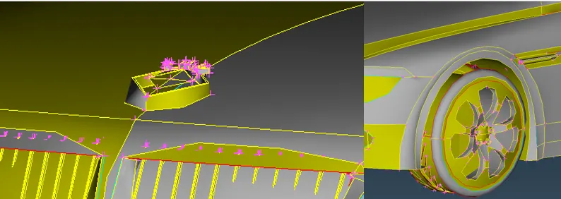
- As observed the geometry has a very poor resolution.
- This can affect the physics while running the simulation.
- This can be done by navigating to LENGTH option in MESH DECK (MESH DECK >> PERIMETERS >> LENGTH).
- Assign a value of 1mm.
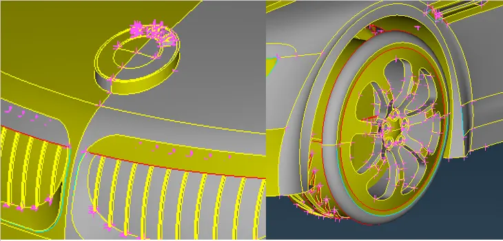
- Resolution is much better than before.
- Now we can resolve the errors part by part.
Exploring the UNIVERSAL DELETE option:
- Since the model is symmetrical, we will be deleting one half of the car geometry, clean the remaining half and the apply symmetry optoin after completeing the clean up.
- UNIVERSAL DELETE option is present in the top ribbon.
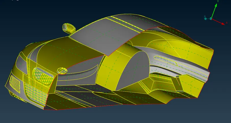
- Now we will workout on the remaining half of the geometry.
>> Exploring the PASTE option:
- This is used to paste one con onto other con.
- Select PASTE option. (TOPO DECK >> CONS >> PASTE).
LOGO CLEAN UP:
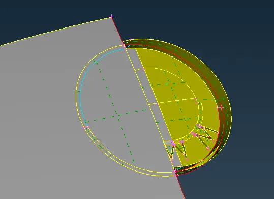
- Major clean up is required at the bottom of the logo.
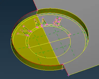
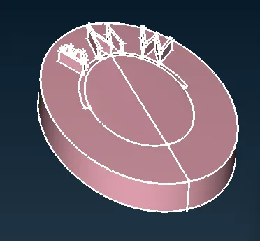
- We must clean the the unwanted surfaces using UNIVERSAL DELETE option.
- Final output must be like the figure shown below:
GRILLS CLEAN UP:
- There are lot of unnecessary surfaces.
- Objective here is to keep a common volume inside the car so we will be deleting/modifying few surfaces.
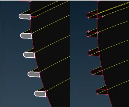
- The above selected surfaces are not required. So we can go ahead and delete the surface.
- We have to create a comman volume.
>> Exploring the PROJECT option:
- This will project the cons on the surface.
- Select PROJECT option. (TOPO DECK >> CONS >> PROJECT).
>> Exploring the NEW option:
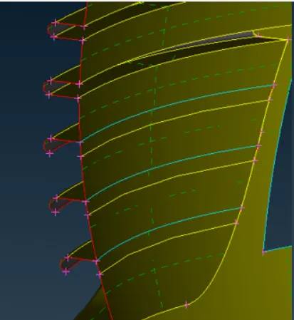
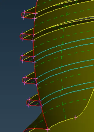
- This tool is used to create new surface/face.
- Select NEW option. (TOPO DECK >> FACES >> NEW).
Before:
After:
>> Exploring the EXTEND option:
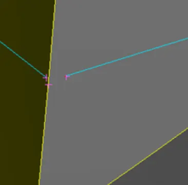
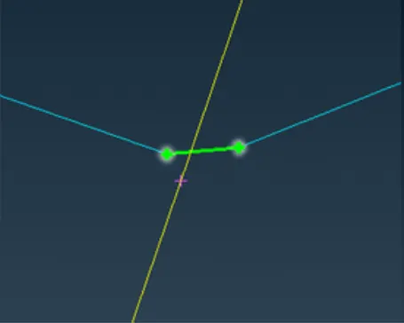
- This tool will extend the cons on a particular surface of interest.
- It only works for red cons.
- Select EXTEND option. (TOPO DECK >> FACES >> EXTEND).
- The final objective is shown below:
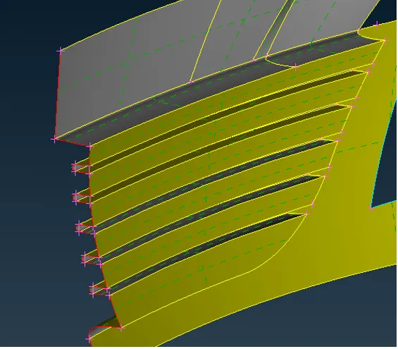
- The red cons will go away once we do symmetry.
SIDE GRILL CLEAN UP:
- Objective is to create a common volume.
- Eliminate the red cons and avoid blue cons.
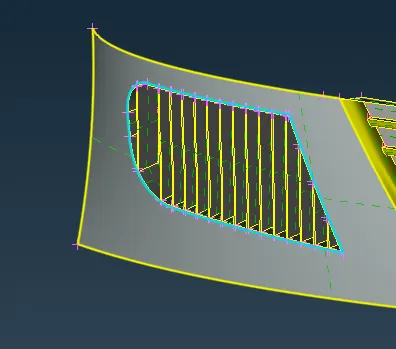
- We will be removing the triple cons first.
- It is quite evident that there is no triple cons present there after using the UNIVERSAL DELETE option.
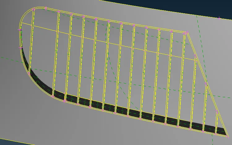
- The ribs in the above figure will form its own local volume.
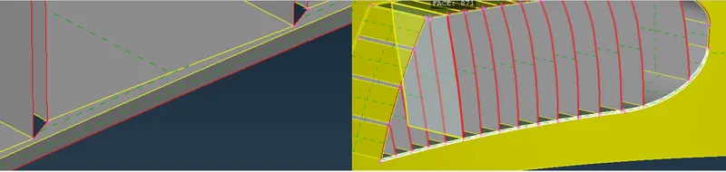
- Inorder to avoid local volume formation, we must open the ribs from the rear end.
- The ribs in the above figure will form its own local volume.
- Inorder to avoid local volume formation, we must open the ribs from the rear end.Delete the surfaces as shown in the figure below:
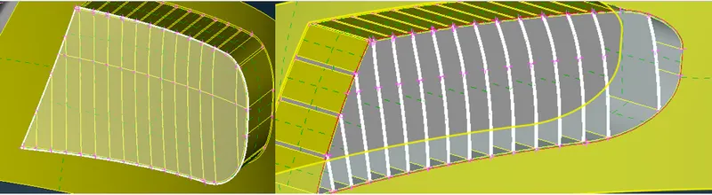
- Now its time to make some modification to the existing surface.
- This is done using the CUT option. (TOPO DECK >> FACES >> CUT).
- Similarly, we will be modifying the upper surface.
- We will be creating lines to delete unwanted surfaces.
- This can be done using CUT option to create the lines. (TOPO DECK >> FACES >> CUT).
- And lateron surfaces can be deleted using UNIVERSAL DELETE option.
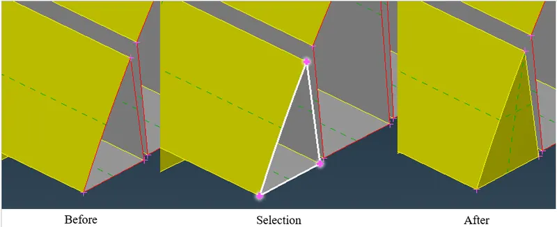
>> Exploring the FILL HOLE option:
- This tool is used to fill an empty surface.
- Select FILL HOLE option. (TOPO >> FACES >> FILL HOLE ).
>> Exploring the PARAMETRICAL option:
- This tool allows us to create a hot point at some distance from any local reference location.
- Select PARAMETRICAL option. (TOPO DECK >> HOT POINTS >> PARAMETRICAL).
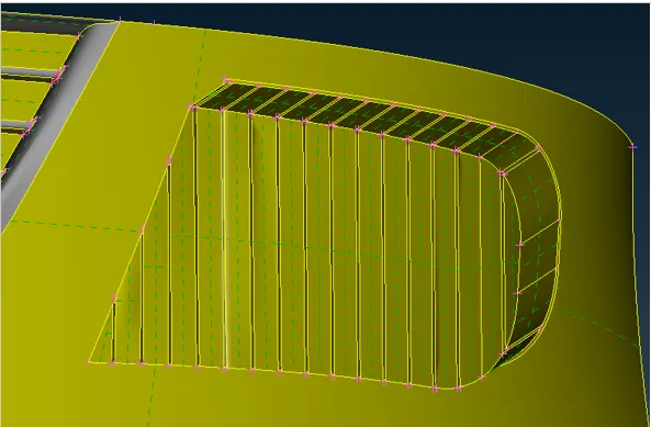
- The final output should be as shown in the figure below:
UPPER GRILL CLEAN UP:
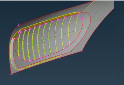
- Obejctive here is to keep common volume inside the car.
- Make sure that we do not form local volume.
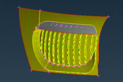
>> Exploring the PROJECT option:
- This tool allows us to project cons on seleted surface/face.
- Select PROJECT option. (TOPO DECK >> CONS >> PROJECT).
- We will be projecting cons on to surface as shown in the figure below:
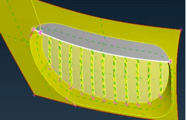
>> Exploring the PROJECT CUT option:
- This tool allows you to create a cut perpendicular to the choosen surface and hot point of a con.
- Select PROJECT CUT option. (TOPO DECK >> FACES >> PROJ.CUT).
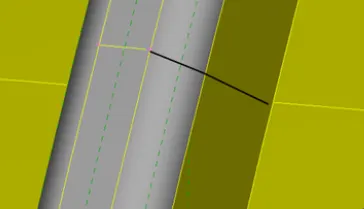
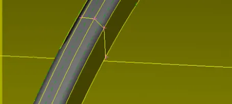
- Next step is to delete the top surfaces using UNIVERSAL DELETE option as shown below:
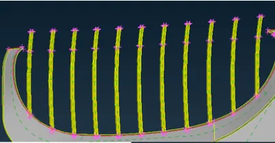
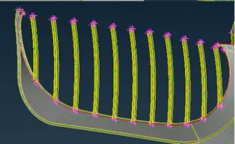
- Now we can go ahead and create new surfaces as shown below:
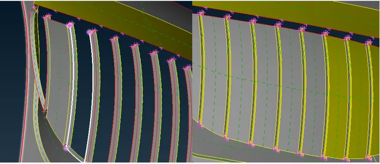
- Lastly we have to close the region.
>> Exploring the MULTI PROJECT option:
- This tool helps us to create multiple hot points with respect to local reference hot points.
- Select MULTI PROJECT option. (TOPO DECK >> HOT POINTS >> MULTI PROJECT).
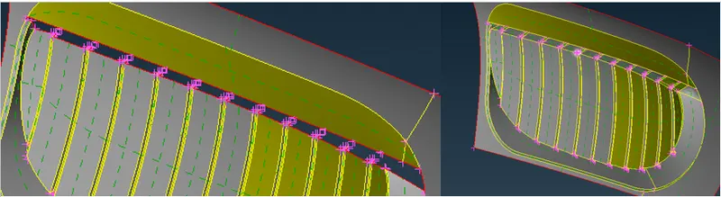
- This solves the final piece off this part as shown below:
DOOR SIDE FEATURE CLEAN UP:
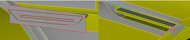
- As visible in the above picture, there are lot of single cons and triple cons with intersecting surfaces.
- We need to clean up those areas with appropriate tools.
>> Exploring the INTERSECT option:
- This tool is used when we see there are three surface meeting and not forming a triple con.
- Select INTERSECT option. (TOPO DECK >> FACES >> INTERSECT).
- There is face which needs to be trimmed, but the cons are incomplete.
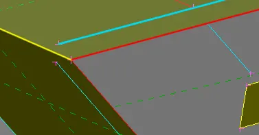
- With the help of PROJ. CUT option we can delete that surface.
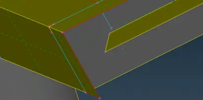
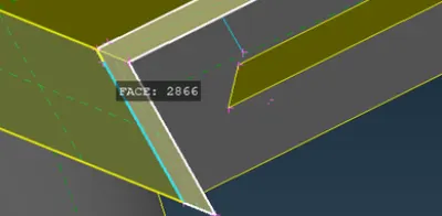
- Next is to extend few surfaces to eliminate the chances of formation of localized volume
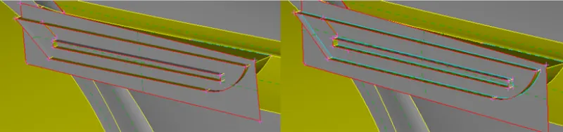
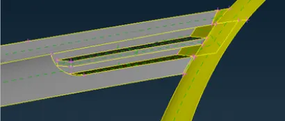
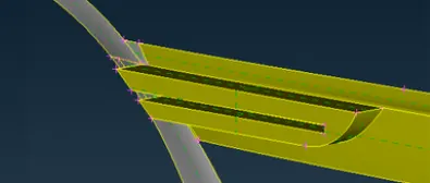
- Still some modification is required. It is done using EXTEND, UNIVERSAL DELETE, CUT etc and many other options.
- Finally, the end result should be some what like as shown in the figure below:
Outside:
Inside:
MIRROR CLEAN UP:
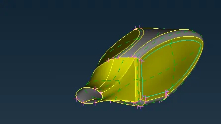
- Objective here is to remove the triple cons.
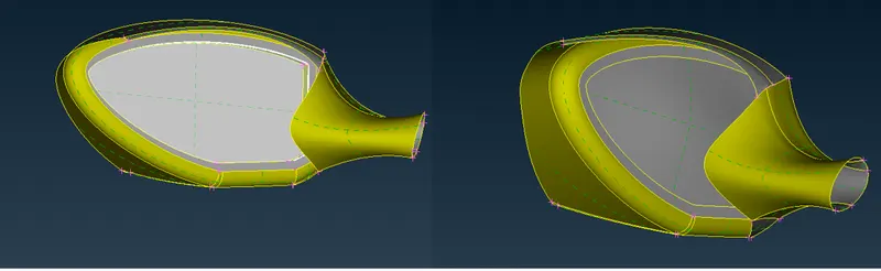
- As you can see there are no triple cons present.
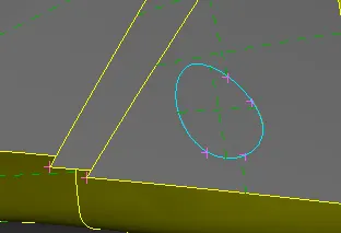
- Since we do not want localized volume to be formed, we must delete this region.
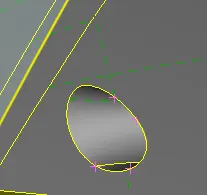
- The clean up mirror is done.
TIRE CLEAN UP:
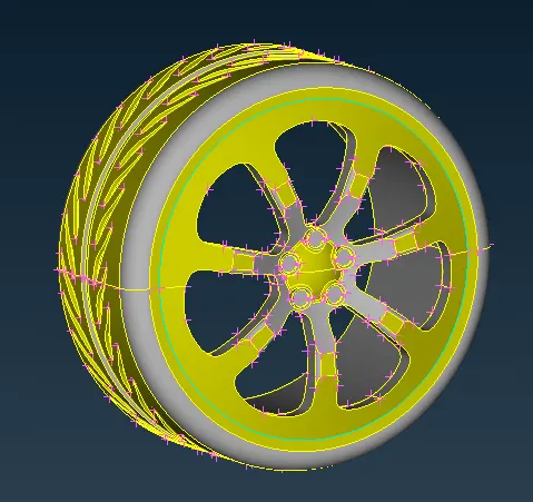
- We will be removing triple cons and overlapping surfaces if present.
- This can be done by hiding few surfaces and deleting unecessary surfaces using UNIVERSAL DELETE option.
Removal triple cone:
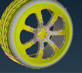
Selection:
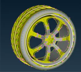
- After selection remove the selected part.
REAR CLEAN UP:
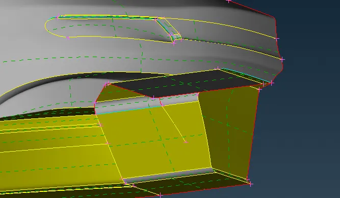
- Triple cons are visible. Simply delete with UNIVERSAL DELETE option.
- The rectified figure can be found below:
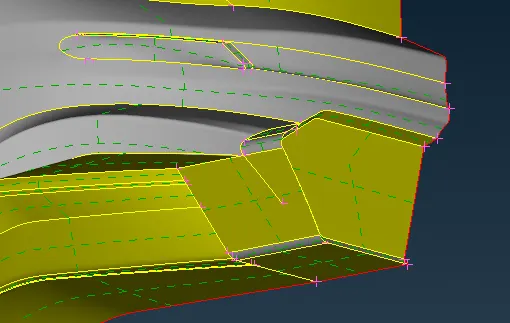
FLOOR CLEAN UP:
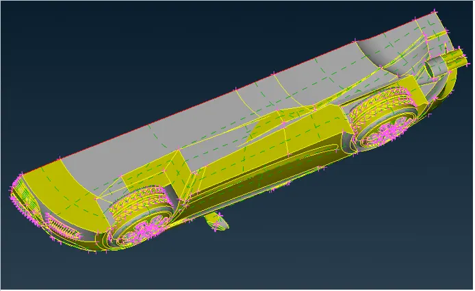
- There are lot of surfaces penetrating into different surfaces.
- The objective here is to removme those surfaces.
- This can be done using UNIVERSAL DELETE option.
- If any surfaces meet and do not form any cons, then it is best prcatice to perform INTERSECT option. (TOPO DECK >> FACES >>INTERSECT).
Intersecting but no formation of comes:
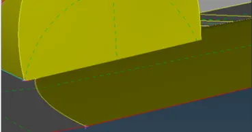
Selection:
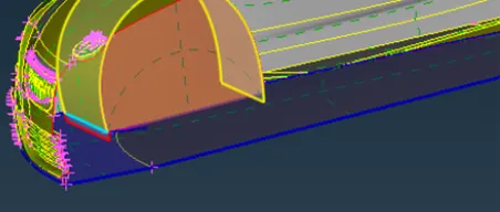
Cons formation:
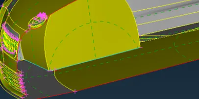
>> Exploring CONS2CURVE option:
- This tools helps in creating curves out of existing cons.
- Objective here is to leave footprints for later use.
- Select CONS2CURVE option. (TOPO DECK >> CURVES >> CONS2CURVE).
- It will change the con colour to purple.
- There are lot of uneven surfaces which needs to be deleted.
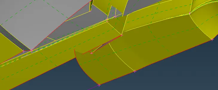
- Since there are lot of surfaces intersecting and not forming an cons, we must use INTERSECT option.
- Select INTERSECT option. (TOPO DECK >> FACES >> INTERSECT).
Selection:
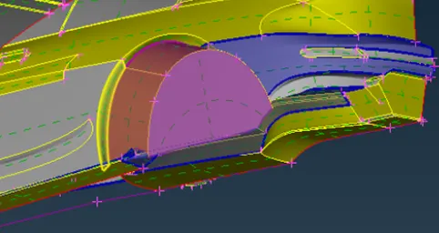
Formation of cons:
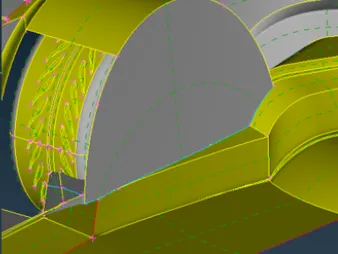
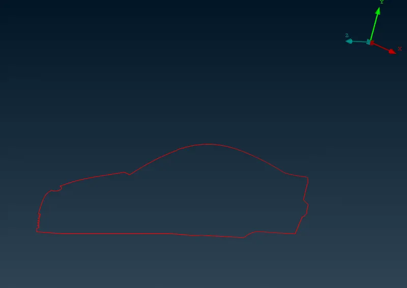
- Comparing befor and after of the floor, the after is much cleaner and has les overlapped surfaces as seen in the below figure:
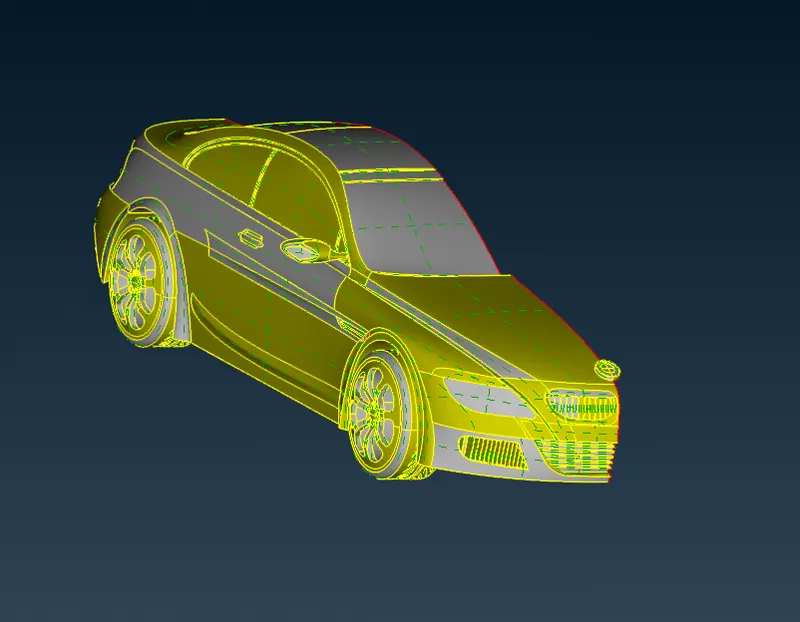
- And there should no single and triple cons except the middle cross section single con.
ASSIGNING PID'S:
- The next phase of the pre-processing is to assign PIDs to respective component.
- This allows you to work with the model fluently without any chances of facing any error or creating confusion over similar looking parts.
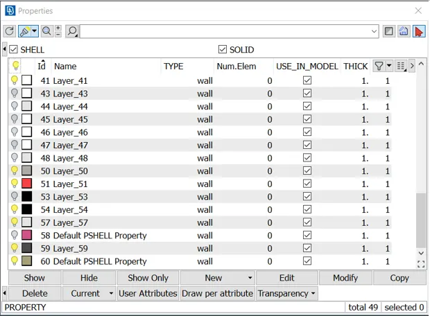
- Figure below shows the default PIDs assigned to the component:
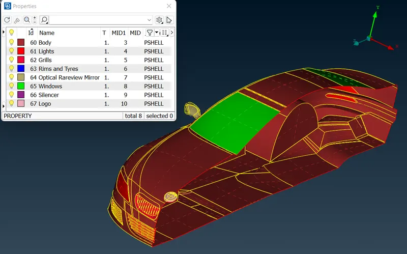
- To create new PID, right click and you will see NEW option. Selecting NEW, will allow you to set and apply PIDs.
- Assing the names of the PID's according to the component.
- And delete the unwanted PID's. This can be done by selecting COMPRESS option present in ribbon at top left corner.
- Inorder to APPLY PIDs, we will isolate the component and then assign the PIDs.
MESHING:
Target lengths for the different parts of a model are as follow:
- Body - 3 mm
- Lights - 4 mm
- Grills - 1 mm
- Rims and Tyres - 2 mm
- Optical Rear view mirror - 2 mm
- Window - 2 mm
- Silencer - 3 mm
- Logo - 1 mm
- There should be no off elements in the meshing.
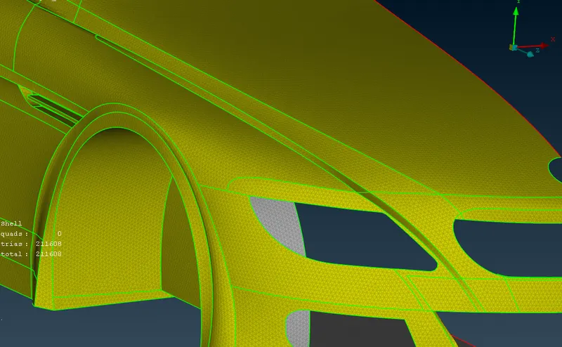
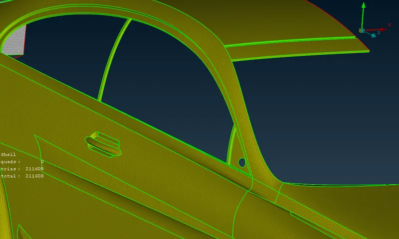
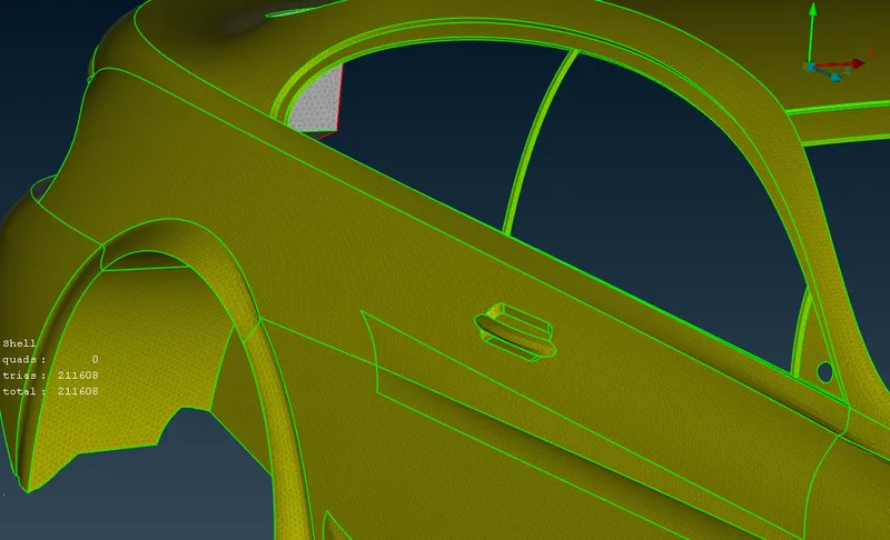
1. Meshing the Body:
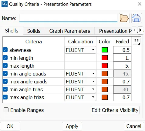
- Before initiating the mesh, MESH PARAMETER and QUALITY CRITERIA must be assigned.
- Target Length = 3 mm
- Minimum Length = 1 mm
- Maximum Length = 5 mm
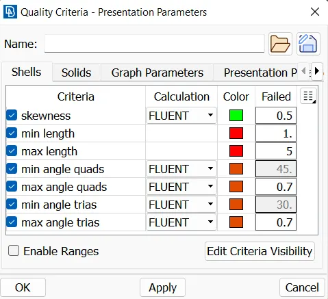
- Select LENGTH option. Assign same mesh length value for both perimeter and macros (MESH DECK >> PERIMETERS >> LENGTH).
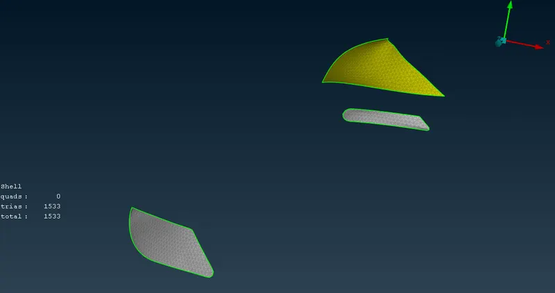
2. Meshing the lights:
- Before initiating the mesh, MESH PARAMETER and QUALITY CRITERIA must be assigned.
- Target Length = 4 mm
- Minimum Length = 3 mm
- Maximum Length = 5 mm
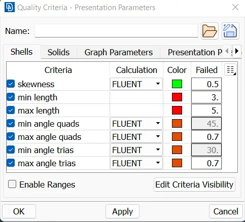
- Select LENGTH option. Assign same mesh length value for both perimeter and macros (MESH DECK >> PERIMETERS >> LENGTH).
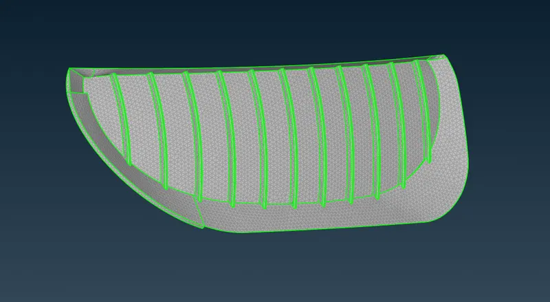
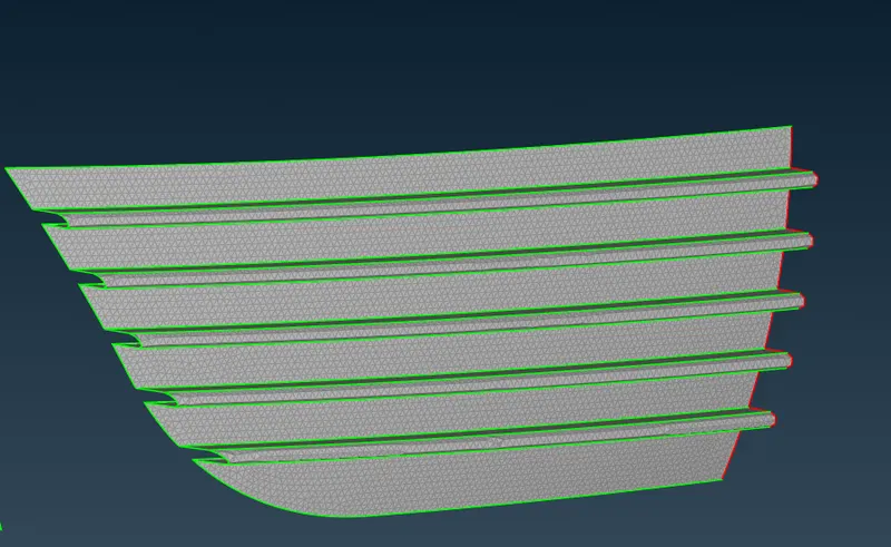
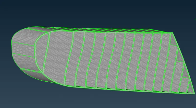
3. Meshing the Grills:
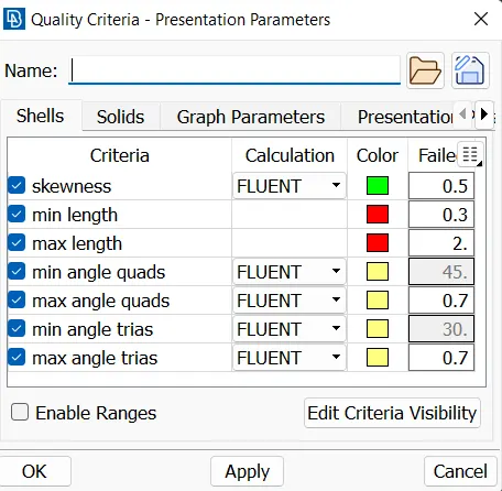
- Before initiating the mesh, MESH PARAMETER and QUALITY CRITERIA must be assigned.
- Target Length = 1 mm
- Minimum Length = 0.3 mm
- Maximum Length = 2 mm
- Select LENGTH option. Assign same mesh length value for both perimeter and macros (MESH DECK >> PERIMETERS >> LENGTH).
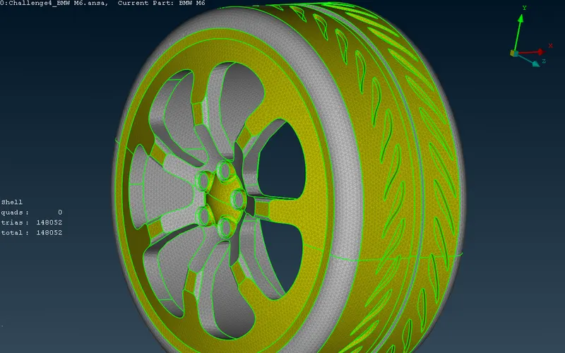
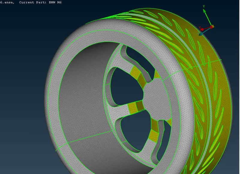
4. Meshing the Rims and tyres:
- Before initiating the mesh, MESH PARAMETER and QUALITY CRITERIA must be assigned.
- Target Length = 2 mm
- Minimum Length = 1 mm
- Maximum Length = 3 mm
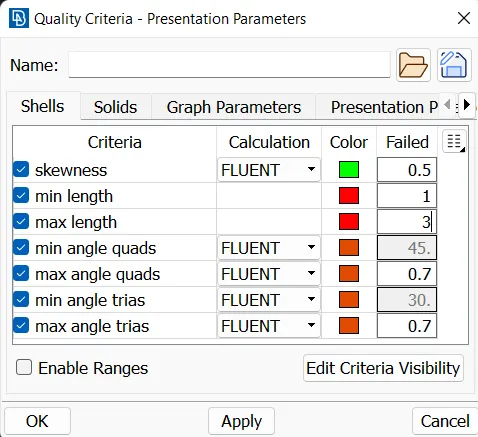
- Select LENGTH option. Assign same mesh length value for both perimeter and macros (MESH DECK >> PERIMETERS >> LENGTH).
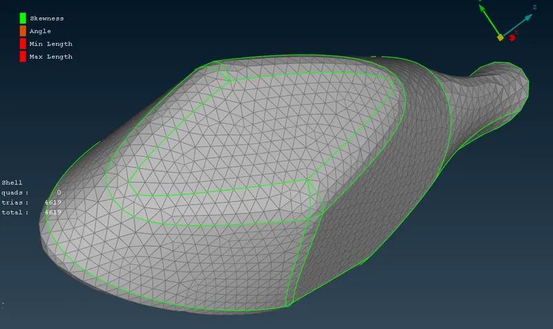
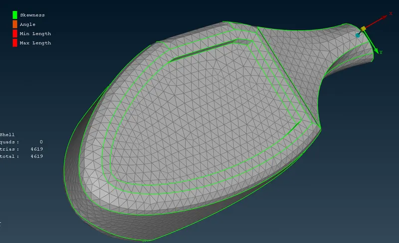
5. Meshing the Optical mirrors:
- Before initiating the mesh, MESH PARAMETER and QUALITY CRITERIA must be assigned.
- Target Length = 2 mm
- Minimum Length = 1 mm
- Maximum Length = 3 mm
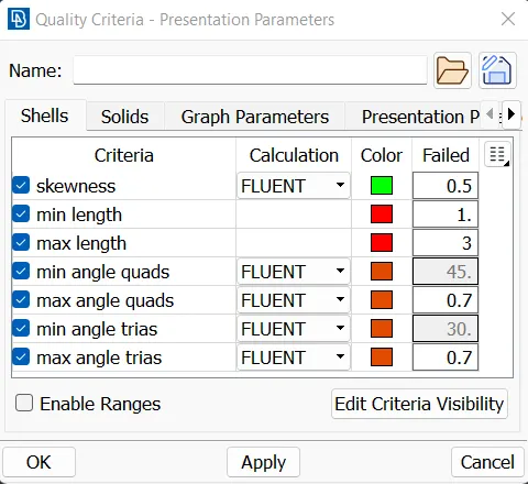
- Select LENGTH option. Assign same mesh length value for both perimeter and macros (MESH DECK >> PERIMETERS >> LENGTH).
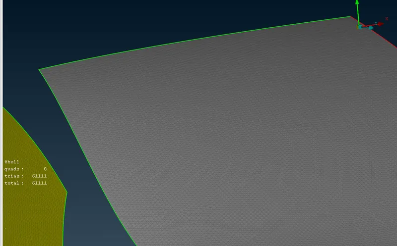
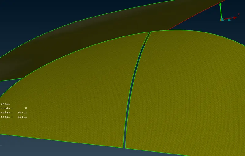
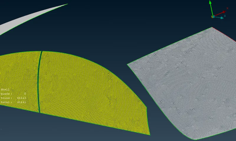
6. Meshing the Windows:
- Before initiating the mesh, MESH PARAMETER and QUALITY CRITERIA must be assigned.
- Target Length = 2 mm
- Minimum Length = 1 mm
- Maximum Length = 3 mm
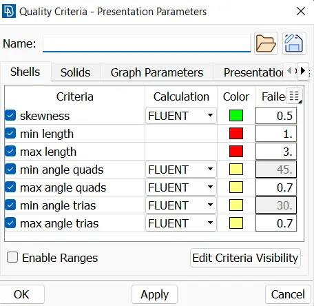
- Select LENGTH option. Assign same mesh length value for both perimeter and macros (MESH DECK >> PERIMETERS >> LENGTH).
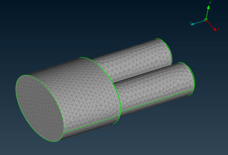
7. Meshing the silencer:
- Before initiating the mesh, MESH PARAMETER and QUALITY CRITERIA must be assigned.
- Target Length = 3 mm
- Minimum Length = 1 mm
- Maximum Length = 5 mm
- Select LENGTH option. Assign same mesh length value for both perimeter and macros (MESH DECK >> PERIMETERS >> LENGTH).
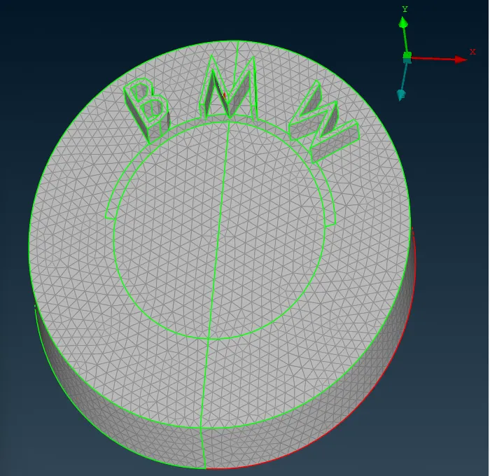
8. Meshing the Logo:
- Before initiating the mesh, MESH PARAMETER and QUALITY CRITERIA must be assigned.
- Target Length = 1 mm
- Minimum Length = 0.4 mm
- Maximum Length = 2 mm
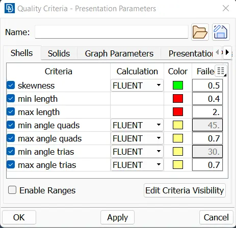
- Select LENGTH option. Assign same mesh length value for both perimeter and macros (MESH DECK >> PERIMETERS >> LENGTH).
SYMMETRY THE MODEL:
- Select proper view for proper selection of the model.
- Select TRANSFORM option present at the right hand side of the viewport.
- Select COPY option. It will ask you to select the entities to copy.
- Select the entire car except the logo.
- Then select the symmetry option
- Select any three point along the line representing as the symmetry plan
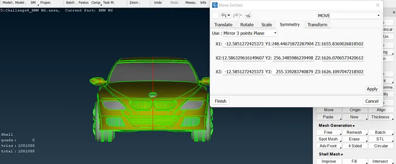
- It shows the entities direction, look at the preview and finish the symmetry.
- After symmetry the whole body will be displayed on the screen.
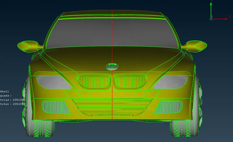
- The middle red cons will be there after the symmetry. So we have to remove the red cons by selecting the paste option.Therefore double cons are formed.
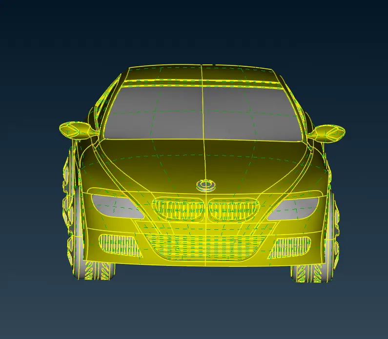
- Then the figure looks like.
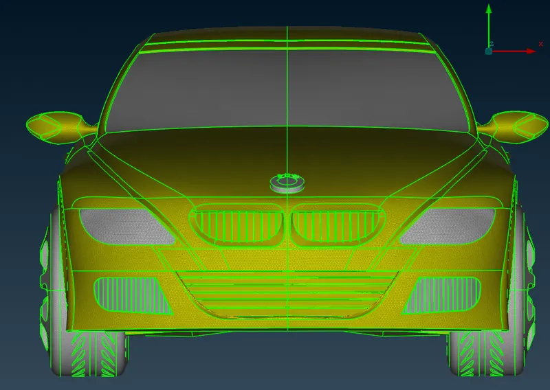
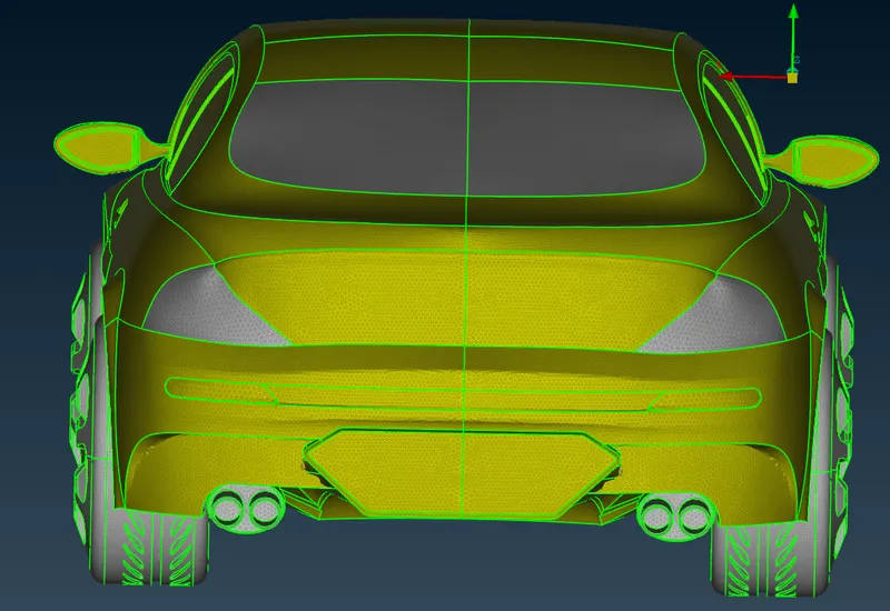
- Meshing is also done on the symmetry part.
WIND TUNNEL :
- There are few standards to be followed to make a wind tunnel.
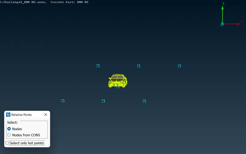
>> Exploring the RELATIVE option:
- This tool helps in creating a point relative to an already selected point in either x,y or z direction.
- Select RELATIVE option. (TOPO DECK >> POINTS >> RELATIVE).
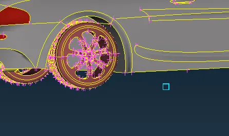
- A point is created.
- With the similar approach we can create more points using RELATIVE option.
- Front Point = 5854 mm.
- Rear Point = 8410 mm.
- Top Point 3900 mm from top point.
- Side Point = 1300 for both sides.
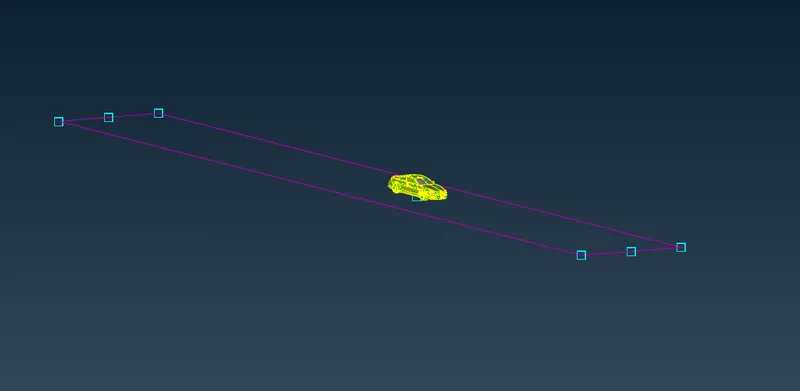
- These points can be used to create curves.
- Select CREATE option. (TOPO DECK >> CURVES >> CREATE).
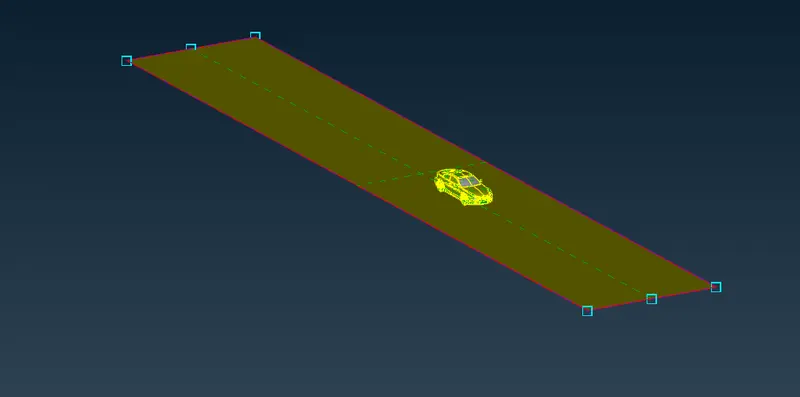
- Using this one can create surface/face.
>> Exploring the OFFSET option:
- This tool helps in creating a surface/face offset from selected entity.
- Select OFFSET option. (TOPO DECK >> FACES >> OFFSET).
- Offset value = 4275 mm.
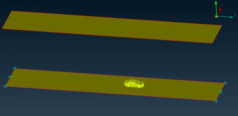
- Creat all the surfaces by taking the reference of top and base surfaces
- Finally, the wind tunnel looks like this
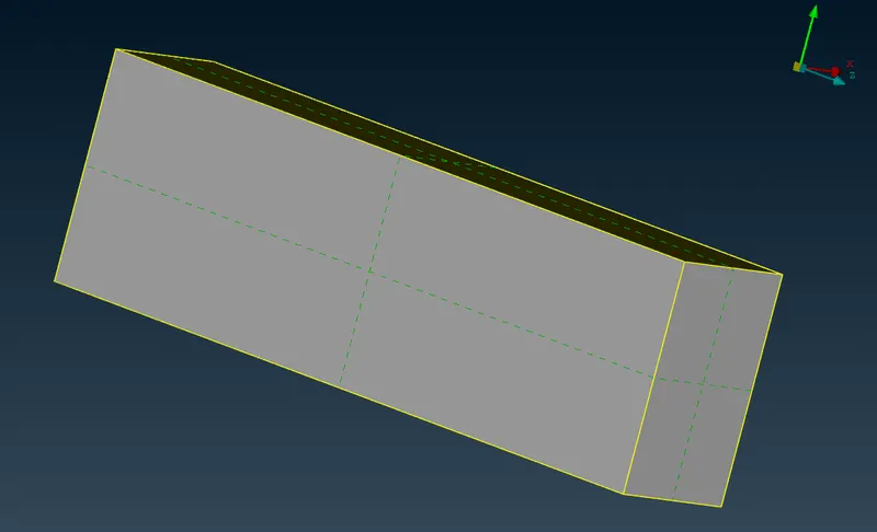
- Assign the PID's accordingly to the surfaces.
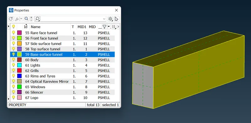
MESHING THE WIND TUNNEL:
- As we are closer to the car, we expect to have a finner mesh and as we move away from the car, we expect to have a coarser mesh.
- Turn off the maximum and minimum length quality critera
- Top surface = 100 mm.
- Bottom surface = 20 mm.
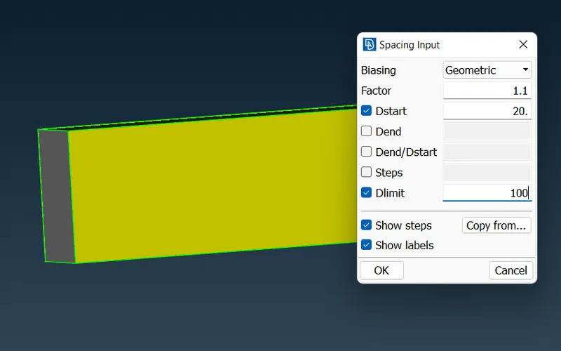
- For side, inlet and outlet we have to give variable mesh length.
- This can be done by using SPACING option.
- Select SPACING option. (MESH DECK >> PERIMETERS >> SPACING).
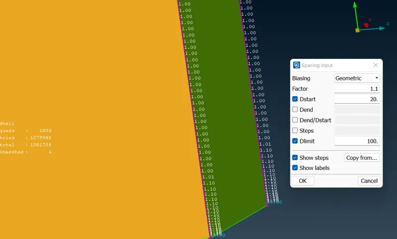
- It will ask few inputs. Please refer below figure:
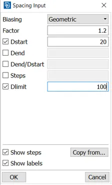
- elect the vertical edges of the box as shown in the figure below:
- So that size of the meshing increases from base surface to the top surface on both the side surfaces according to the given values.
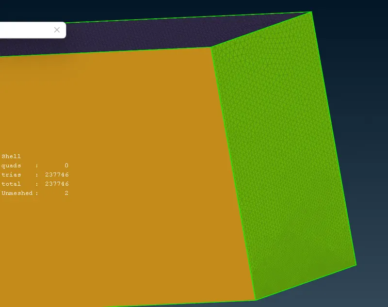
- Finally meshing is done for all the surfaces.
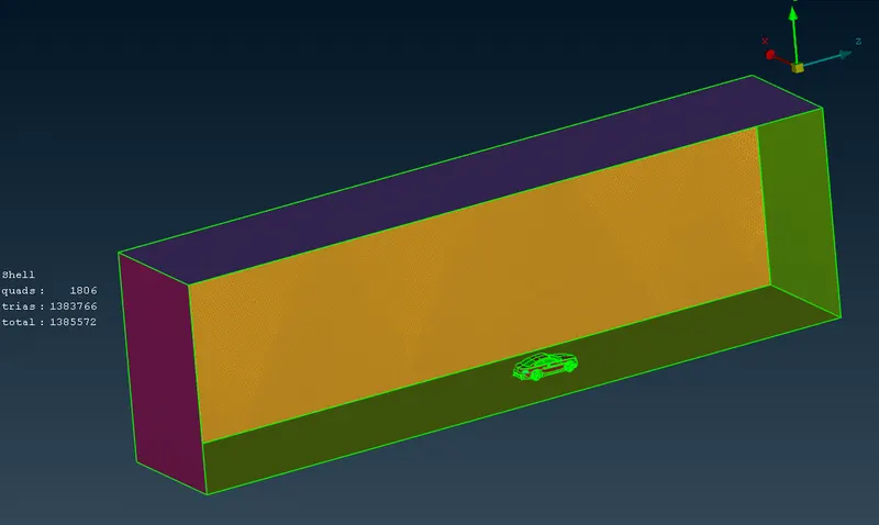
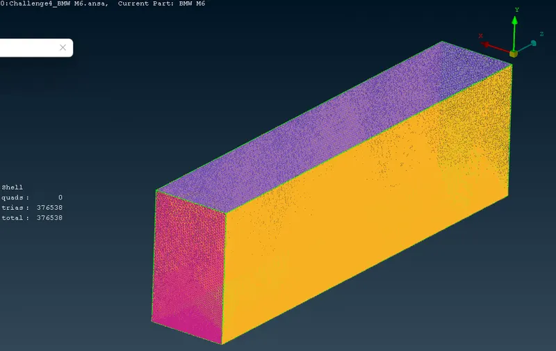
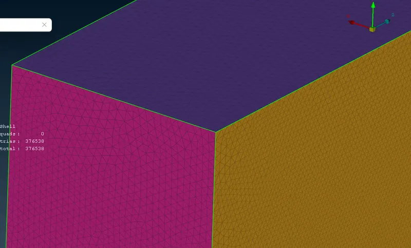
- Finally creating of the win tunnel is complete
- NOTE : In this task volumetric mesh is not performed as it will take lot of time to mesh. Hence the discussion is also not done.
CONCLUSION:
- Learnt how to create a half model.
- Topology clean up part by part with the help of different tools.
- Assigning appropriate PIDs.
- Meshing PIDs one at a time.
- Deligating with off elements and it rectification using different tool approach.
- Creating symmety of the half model.
- Creating wind tunnel and assigning relevent mesh length and variable mesh length.
LINKS OF THE MODEL:
Zip file:
https://drive.google.com/file/d/1zosH_INNf2kEqu-_ZoLl6E0W0YUt65Cm/view?usp=sharing
Normal file:
https://drive.google.com/file/d/1WCmaIb71lCNzFKkVbvMaVkjHp4D2hHCn/view?usp=sharing