Week -2
1.MAKING A SIMULINK MODEL OF A DOOREBELL USING A SOLENOID BLOCK:
- Door bell model
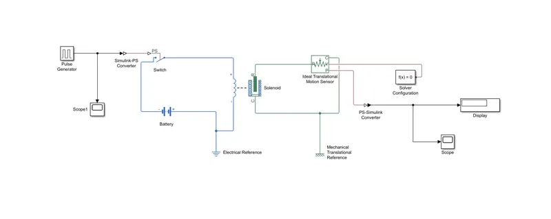
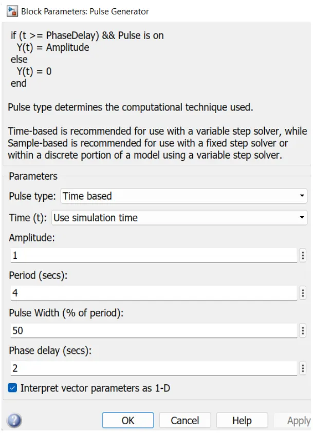
1. Pulse generator : The pulse generator is used to create square wave pulses at regular time intervals. The block wave form parameters ampitude,pulse width,period and phase delay,determine the shape of the output wave form.
2. Switch : The switch block is controlled by the external physiscal signal. if the external physical signal is greater than the thershold parameters then the switch is closed, otherwise switch is open.
3. Battery : The battery block is used in the doorbell model for electrical energy transmisiion. One end of the battery is connected to tthe switch and another end is connected to solenoid.
4. Solenoid : The solenoid block is connected with the switch and battery and will gat a complete electrical circuit. Another end of the solenoid is connected to ideal translation motion sensor and lower end of the solenoid is connected to c port of the ideal translation motion sensor.
5. Electrical reference : Electrica;l reference is used due to the formation of electrical circuit
6. Ideal translation motion sensor : ideal translation motion sensor is connected to solenoid for sensing the signals from the solenoid.
7.Mechanical Translation Refrence : A Mechanical translation refrence is used due to formation of mechanical circuit.
8. PS : Simulink converter is used for converting the signals.
9. Solver configuration : A solver configuration is used for getting the equation of the model.
10. Scope : A scope displays the plot of the model after running the model.
11. Display : A display block shows the output value of the model.
Plot of the pulse generator :
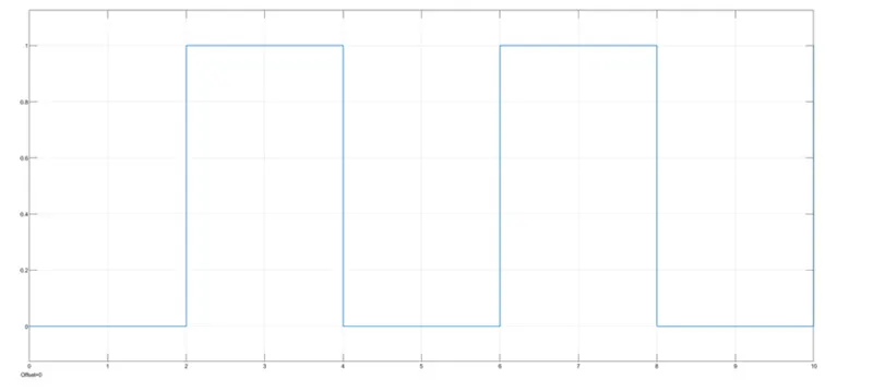
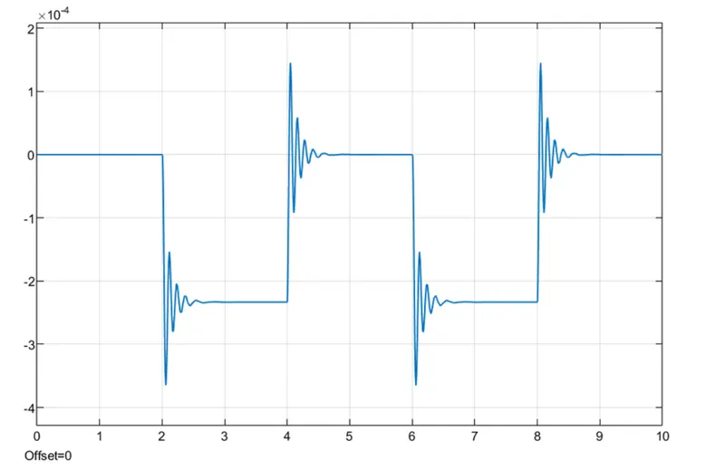
Time peripod given is 2 sec to the pulse genetator to open and close the switch. When the switch is closed the selenoid block recevies electrical power from the battery and plunger moves from port R to C to uhit the bell and produces sound.
Plot of PS_Simulink convertor :
2. USE A THERMISTOR TO SENSOR THE TEMPERATURE OF A HEATER AND TURN ON (OR) OFF THE FAN AS PER THE GIVEN BELLOW CONDITIONS :
THERMISTER MODEL :
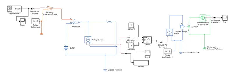
Temperature sorce : 20 degree celsius from 0 to 10 seconds, 27 degree celsius from 10 to 30 seconds, 23 degree celsius from 30 to 50 seconds.
Fan condition : A thermister is a semi conductor that has a resistance capacity more than a conducting material and less tha a insulting material.
it's electrical resistance varies with the change in the tempp or thermally sensitive resistor. They are namely two types of thermisters they are
- Negative temperature coeffients (NTC).
- positive temperature coeffients (PTC).
Thermister relation with temperature also depends on the material in which it is made. A NTC thermister will decrease its resistance value when temperature increses. Where as a PTC will increse its resistance when it's temperature increases.
Thermister have high sensitib=vity which can be upto 10 percent change per degree celcius and their typical responce time is 0.5 to 5sec with an operating range from -50 to -300 degree celsius.
BLOCKS USED :
1. Signal builder : To generate the signal according to the input conditions given.
2. PS-Simulink converter : This block converters the simulink signals to the represntive physical signals.
3. Controlled temperatue source (CTC) : Provides a temperature physical output base on condtions given to port S.
4. Thermal reference : This block provides the requried intial conditions to the connected thermal block of the solver.
5. Thermister : Uses NTC thermister relation between temperature and resistance.
6. Battery : It is storage device that provides the requried voltage based on the parameter given.
7. Resistor : Resistor which provides a opposing nature of current in a cucuit.
8. voltage sensor : It is used to measure the voltage or potential difference accross any electrical component and it shouls connect in parallel only.
9. Electrical reference : These blocks provide the requried intial conditions to the connected thermal block solver.
10. Solver configuration : This block specifies the solver parameters that your model needs before you can begin simulation asd this mandatoryvfor all simscape models.
11. PS-Simulink converter : Convertrs physical signal to the respective simulink signals.
12. Constant : it provdes a constant output value.
13. Switch : It has three inputs namely port1, port2 , port3 is a control input where the signal given to port2 is satistisfied with the condition and threshold of the switch block then it passes port1 as output and it is not satisfied then it will pass to port3 as output.
14. Scope : This block represnts the ouput plot.
15. DC motor : This block represents the electrical and tourque characteristics of a DC motor.
16. Mechanical rotational reference : it gives as a reference to the ideal rotational motor sensor.
PLOT IN SIGNAL BUILDER AS A INPUT SIGNAL :
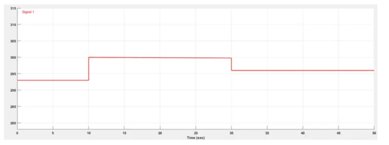
The above plot is signal builder in which the signals are generated according to the given temperature and time. Then generated signals are given as inputs to the contraolled temperature source.
In the plot time is taken 50 sec and temp in 300K.
from 1 to 10 seconds - 293K
from 10 to 30 seconds - 300K
from 30 to 50 seconds - 298K
INPUTS SIGNAL IN SCOPE :
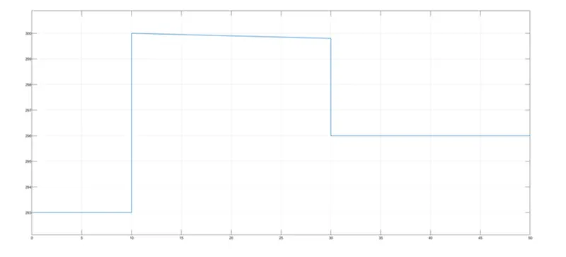
This is the signal plot which shows in the scope which is connected to the signal builder.
OUTPUT SIGNAL OF VOLTAGE vs TIME :
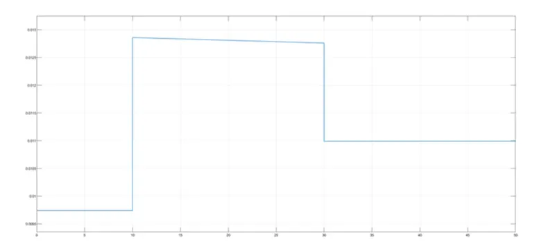
The above plot shows the voltage generated in the voltage sensor.
this plot is shown in th scope which is connected by PS-Simulink convertor and the value of the voltage is displayed in the display block, which is connected by PS-Simulink convertor.
OUTPUT OF THE IDEAL ROTAIONAL MOTION SENSOR :
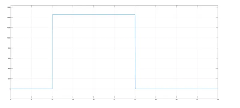
The output of the ideal rotational sensor plotted in the scope.
There is a change in the plot from 10 to 30 sec which shows the angular velocity. The above plot shows the fan conditions ON when the temperature is above 25 degree, by the motor getting power and rotating.