CREATE 1D ELEMENTS ON GIVEN COMPONENT
AIM: CREATE A MESH AND 1D ELEMENT FOR THE GIVEN MODEL WITH CROSS SECTION AND DOF
PROCEDURE:
- Import IGES file to hyper work
- Create a mid surface
- Assign property and material for mid surface
- Create a mesh
- Create rigid connection
- Create 1D elements
- Create hyperbeams
- Assign cross-section
- Assign separate properties
- Apply masses
- Create a spring connection
IMPORT MODEL
Import the IGES file to hyper work
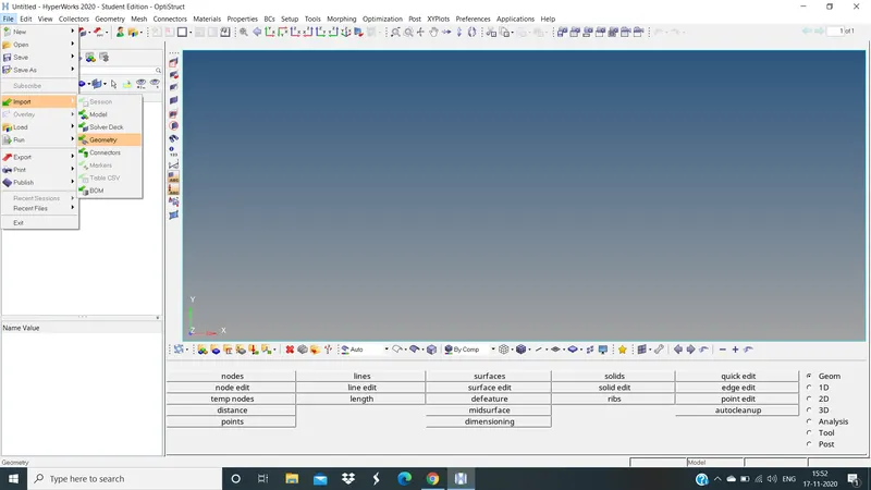
IMPORTING MODEL
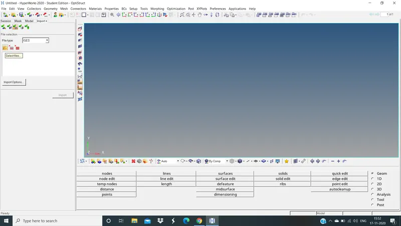
IMPORTING IGES FILE
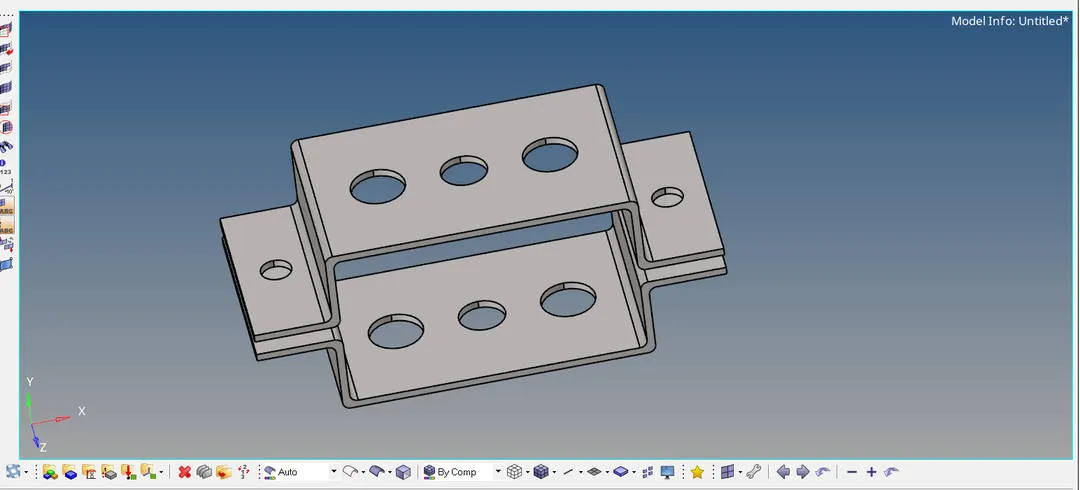
MODEL IMPORTED TO HYPERWORK
CREATING A MID SURFACE
Create a mid surface for the given component
Goto geometry >> Mid surface >> Auto extraction >> Extract
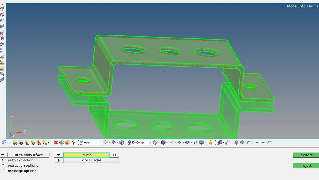
MID SURFACE FOR BRACKET 1
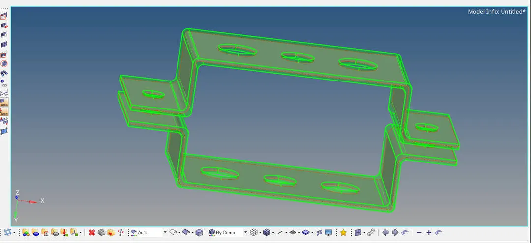
MID SURFACE FOR BRACKET 2
Now rename the mid surface
In left side of graphical part we can see one tab bar
Goto >> model view >> Rename >> Midsurface 1 as bracket 1 and mid surface 2 as bracket 2
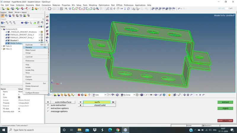
RENAMING AS BRACKET 1 AND 2
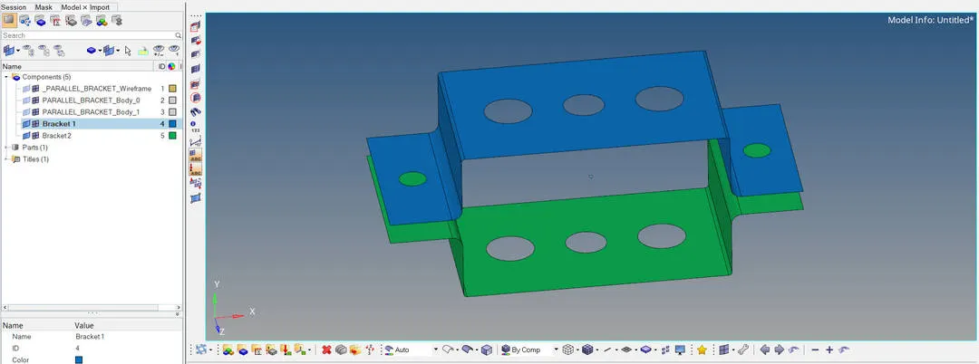
MID SURFACE OF BOTH BRACKETS
ASSIGN PROPERTY AND MATERIAL FOR MID SURFACE COMPONENTS
After creating a mid surfaces
Now create property and material for that components
To create a property and material we have to fallow some steps
Here goto >> Left tab bar >> Create material >> BY right click and create >> Select material type is steel
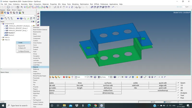
CREATING MATERIAL IN TAB BAR
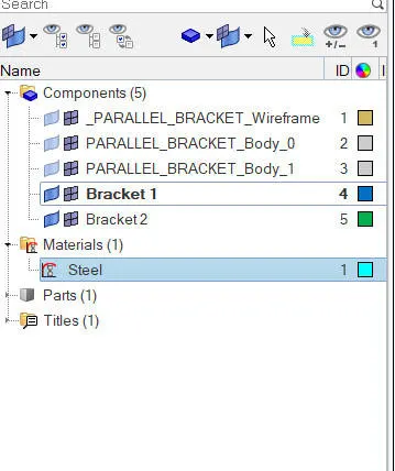
RENAMING OF MATERIAL
Now create a properties in tab bar same as material
Goto tab bar >> Right click >> Create >> Select property >> Type as Bracket 1
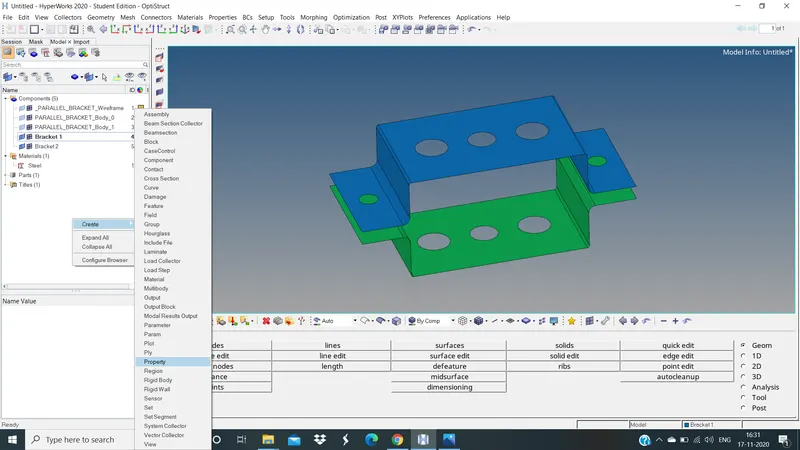
CREATING PROPERTY
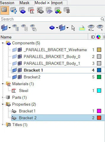
RENAMING PROPERTY AS BRACKET 1 & 2
Now assign for components of braket 1 mid and bracket 2 mid
Assign material and property
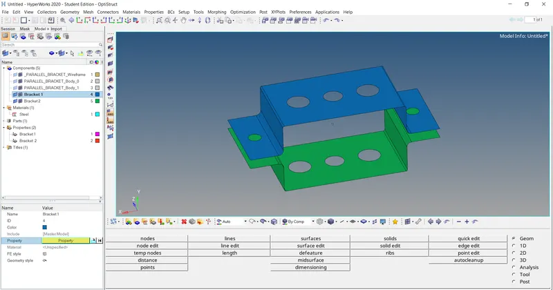
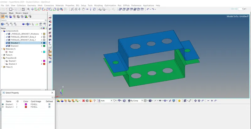
ASSIGNING PROPERTIES FOR BOTH BRACKETS
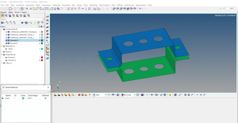
ASSIGNING MATERIAL FOR BOTH BRACKETS
CREATE A MESH
Once assigning all those properties and material move to mesh
Before meshing the component make washer split for the better flow of mesh and equal load transformation
For washer splits
Goto quick edit >> Washer split >> Offest value same as target length >> Create
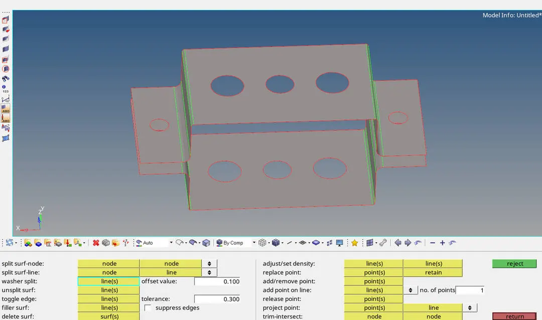
QUICK EDIT TAB
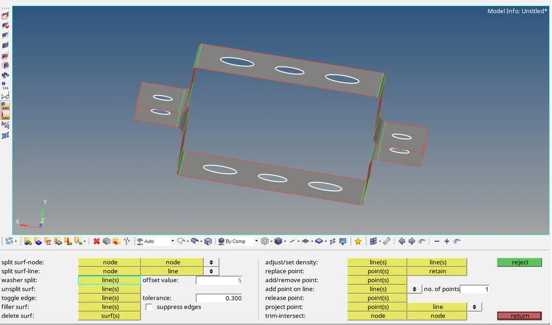
SELECTING WASHER SPLIT AREA
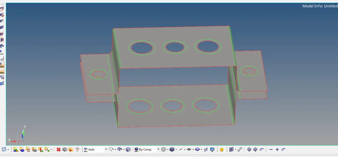
WASHER SPLITS CREATED
Now move to mesh in fillet surface then create split surf line to capture fillet area properly
Mesh the washer splits first then move to other areas
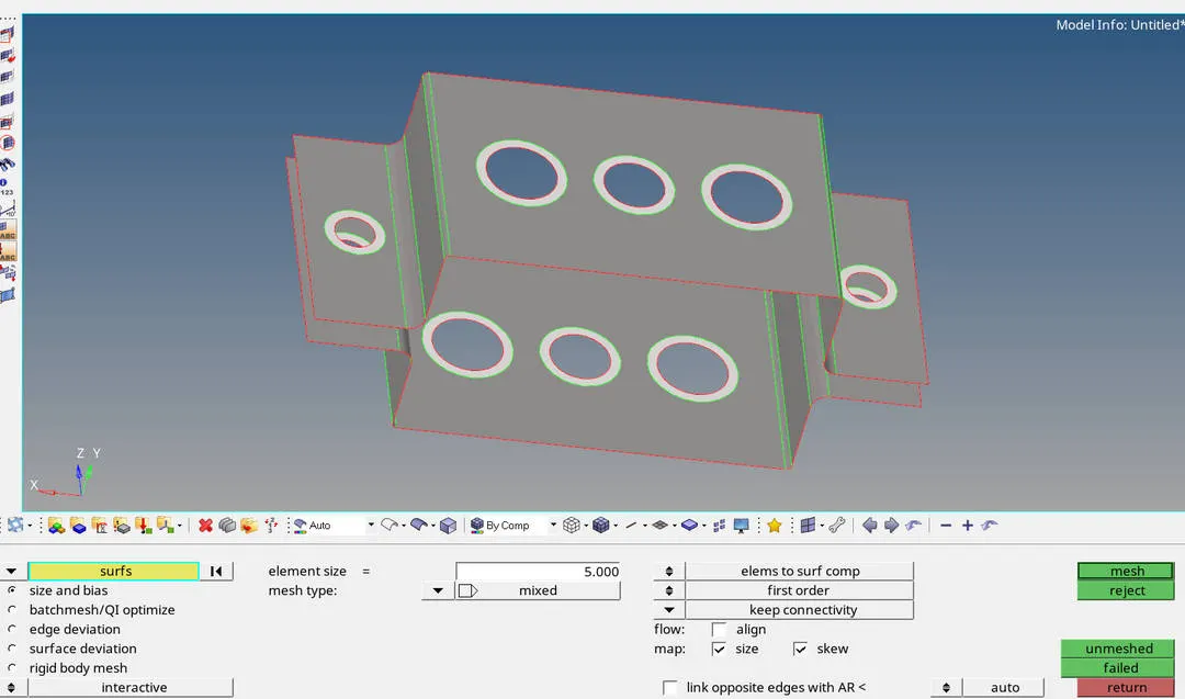
SELECTING WASHER SPLITS TO MESH
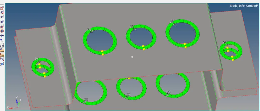
MESH CREATED ON WASHER SPLIT AREA
Here we can see some un equal nodes so that is the reason trias are forming in washer splits area
Here we have to remove those tria by keeping even number of nodes
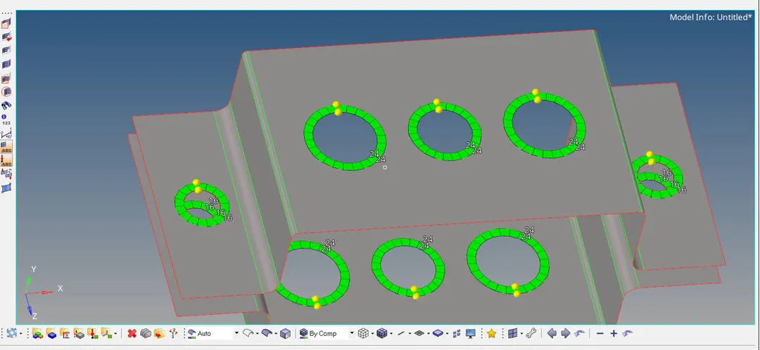
PROPER MESH NEAR WASHER SPLITS AREA
Now mesh rest all of areas
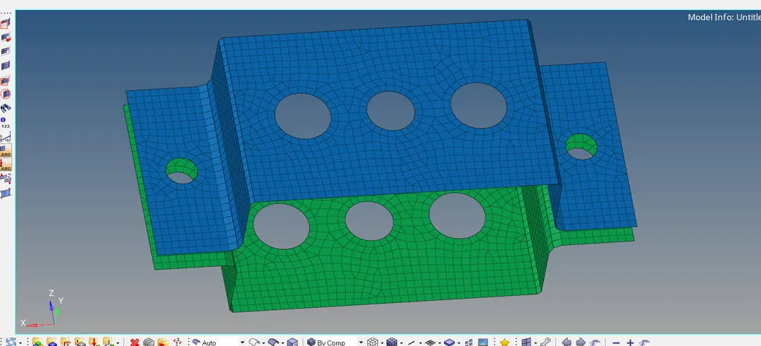
FINAL MESH CREATED ON COMPONENT
CREATE RIGIT CONNECTIONS
Once the mesh is done give rigit connections for the given area
For rigit connections
Goto geometry page >> 1D >> Select rigit (RBE2)
As per given question
a. Rod element:- with only translational DOF and RBE2 link
b. Beam element:- with all DOF and RBE3 link
c. Bar element:- with only x and y DOFs With RBE3 link
For ROD he asked only in transaltion DOF with RBE2 link
So there 6 Dof's are there
DOF 1 = Translational in X direction
DOF 2 = Translational in Y direction
DOF 3 = Translational in Z direction
DOF 4 = Rotational in X direction
DOF 5 = Rotational in Y direction
DOF 6 = Rotational in Z direction
Here for rod elements we need only DOF 1,2 and 3
So enable DOF 1,2 and 3 only
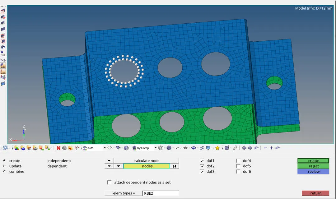
SELECTING NODE AND DOF FOR ROD
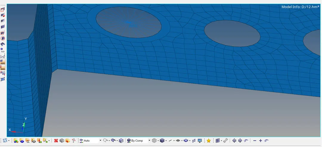
RBE2 RIGIT LINK CREATED FOR ROD
Now for beam element RBE3 link with all DOF's
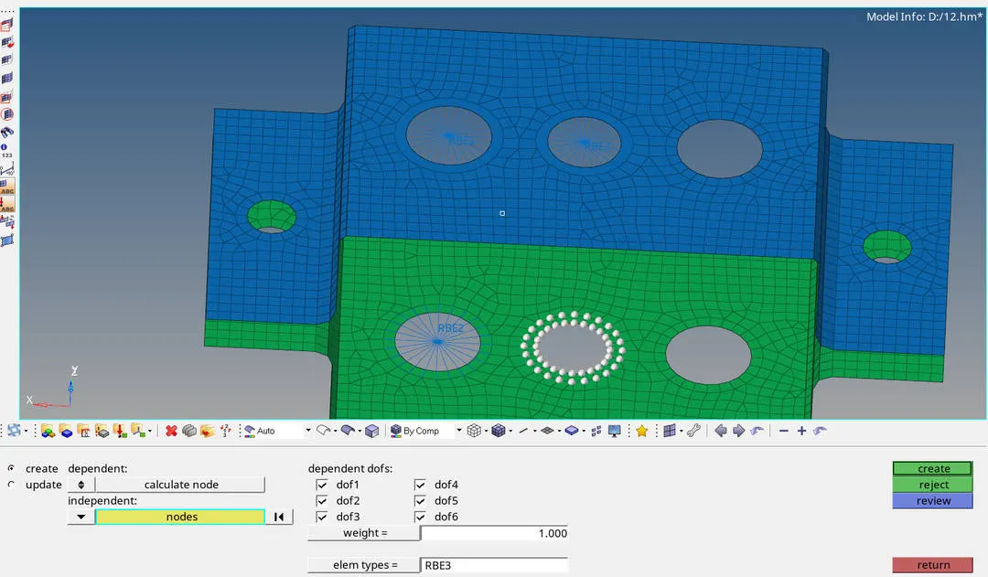
SELECTING NODES AND DOF FOR BEAM
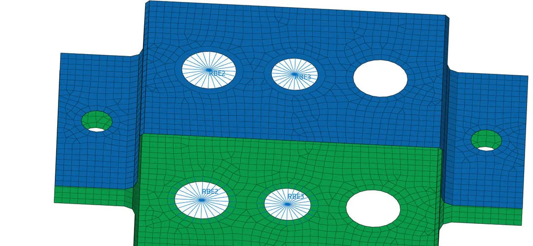
RBE3 LINK IS CREATED
Now for bar elements only X and Y DOF
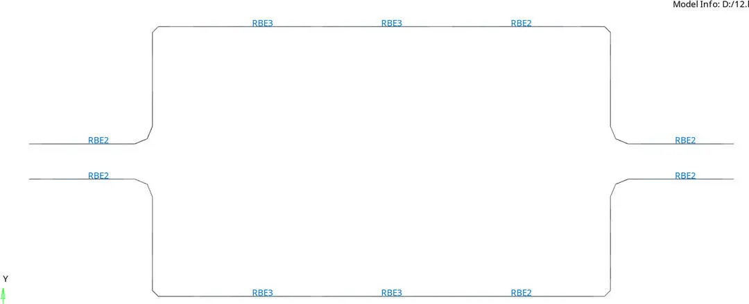
ALL RIGIT LINKS ARE CREATED
CREATE HYPERBEAM
To create a hyperbeam
Goto geometry page >> 1D >> Hyperbeam >> Standared section >> Hyper mesh >> thinwalled box >> Create
Cross-Section: BOX- Dimension a= 12 mm
dimension b=10 mm
Thickness t= 0.75 mm
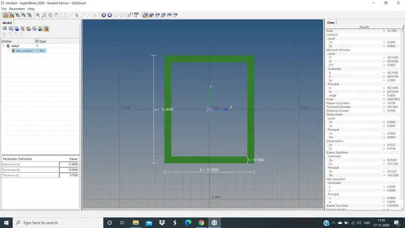
HYPERBEAM CREATED FOR ROD
In left side tab bar we can create other type as well no need to go back for create I section beam again
Just right click on tab bar >> Create >> Standared >> Hypermesh >> Standared I-section >> enter the values
Cross-Section: I-Section- Dimension a= 8 mm
Dimension b= 10 mm
Dimension c= 8.5 mm
Thickness t1= 0.75 mm
Thickness t2= 0.6 mm
Thickness t3= 0.6 mm
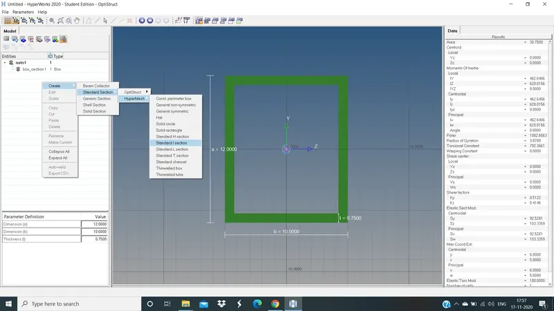
CREATING I-SECTION BEAM
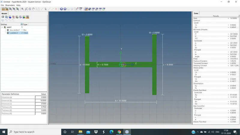
HYPERBEAM IS CREATED FOR BEAM
Now for bar cross section same as beam
Right click on tab >> Create >> Standared >> Optistruct >> Cross
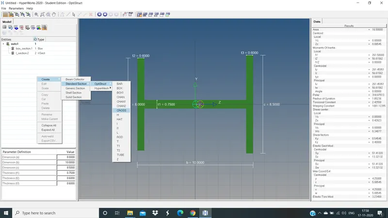
CREATING CROSS SECTION FOR BAR
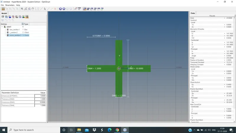
HYPERBEAM IS CREATED FOR BAR
If we go back we can see the updated beam in tab bar
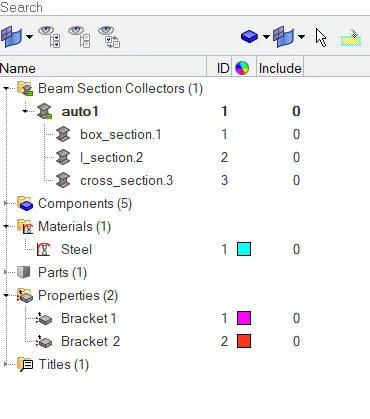
UPDATED BEAM TAB
CREATE 1D ELEMENTS
First give connection for rod
Goto geometry page >> 1D >> Rod's >> Select master node 1 and 2 >> Middle click
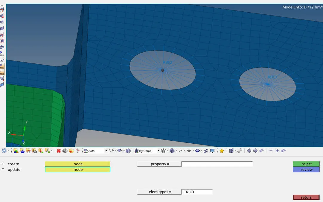
SELECTING MASTER NODES TO CREATE 1D ROD ELEM
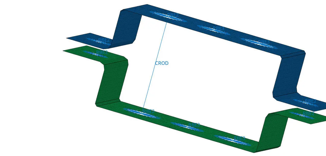
1D ROD ELEM IS CREATED
Next connection for beam
Goto geometry page >> 1D >> Bar's >> Select element type as CBEAM >> Select node 1 and node 2 >> Give orientation >> Create
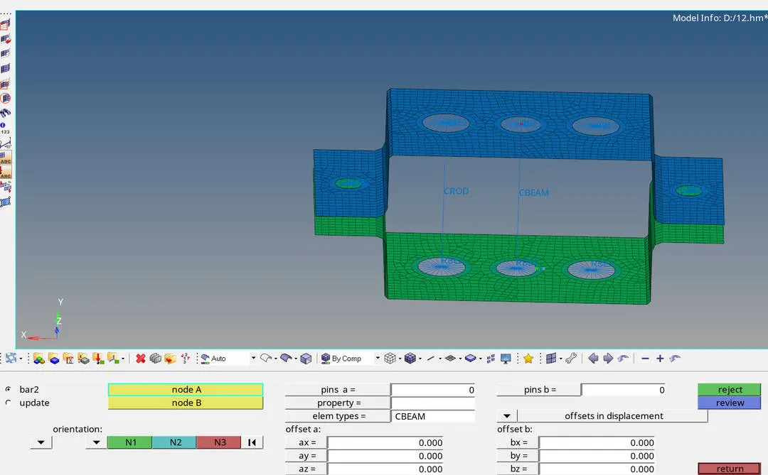
1D ElEM FOR BEAM IS CREATED
Same for Bar too
Goto geometry page >> 1D >> Bar's >> Select element type as CBAR >> Select node 1 and node 2 >> Give orientation >> Create
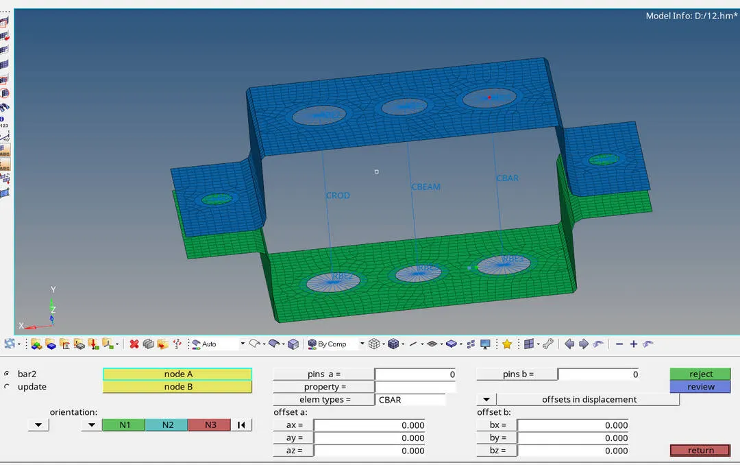
1D ElEM FOR BAR IS CREATED
ASSIGN CROSS SECTION FOR BEAM's
Once all the 1D elements are created
We have to assign cross section for rod, beam and bar
So all these beams are in bracket 1 we have to create different properties of ROD, BEAM and BAR
To create these properties
Goto tab bar >> right click >> create >> property

CREATING PROPERTIES
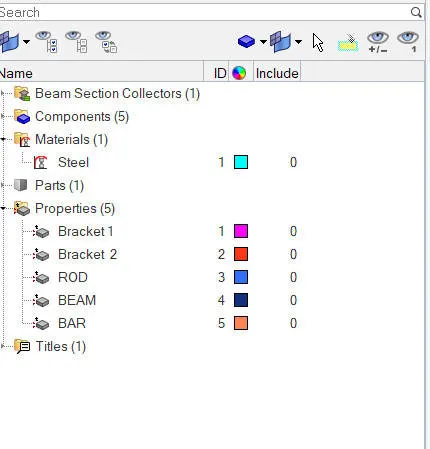
PROPERTIES CREATED
ASSIGN SEPERATE PROPERTIES
After creating properties assign seperate proprty like rod type, property of brackets etc..
Goto Rod property >> Select card image as PROD >> beam section as box section(Rod cross section).
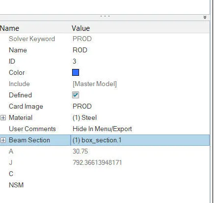
PROPERTY FOR ROD
For beam
Goto Beam property >> Select card image as PBEAM >> beam section as I-section(Beam cross section).
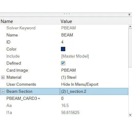
PROPERTY FOR BEAM
For Bar
Goto Bar property >> Select card image as PBAR >> beam section as cross-section(Bar cross section).
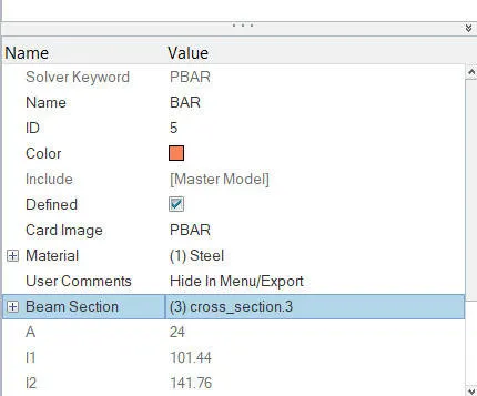
PROPERTY FOR BAR
Now update this properties for CROD, CBEAM and CBAR
Goto geometry page >> 1D >> Rod >> Select property as rod >>Element type as CROD >> update
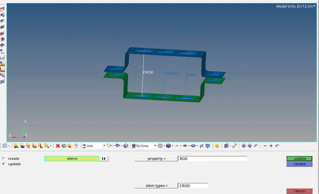
UPDATING PROPERTY OF ROD
For beam
Goto geometry page >> 1D >> Bar's >> Select property as beam>>Element type as CBEAM >> update
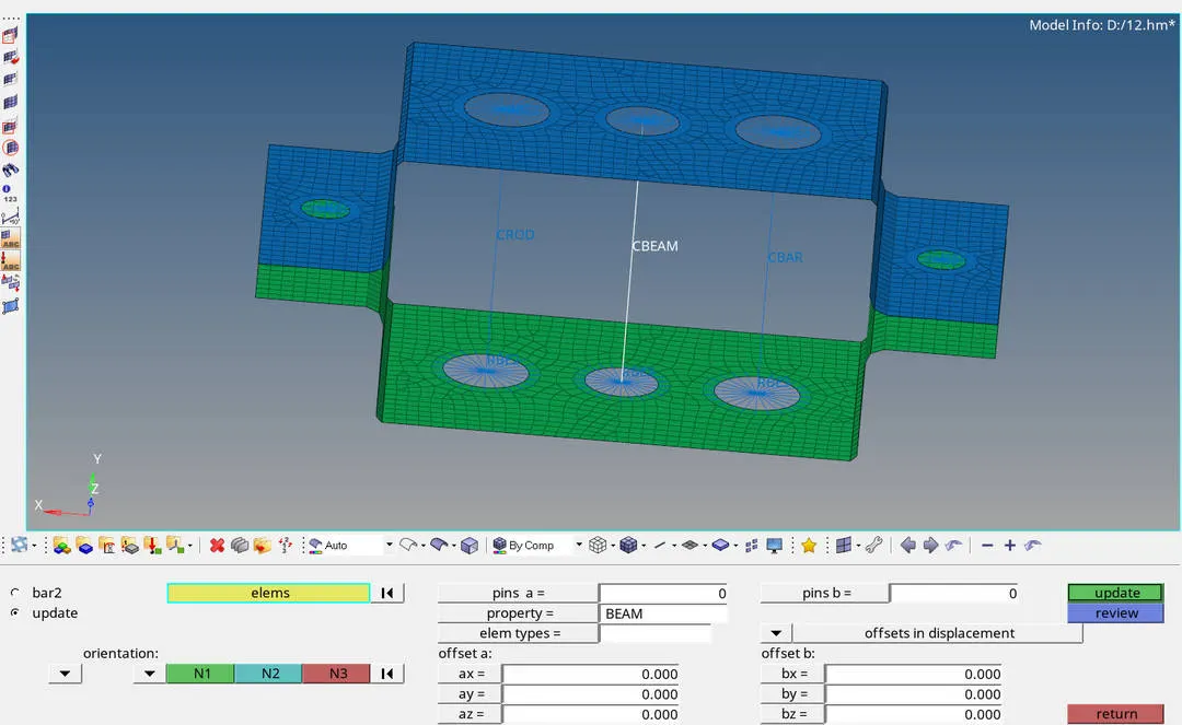
UPDATING PROPERTY OF BEAM
For bar
Goto geometry page >> 1D >> Bar's >> Select property as bar >>Element type as CBAR >> update
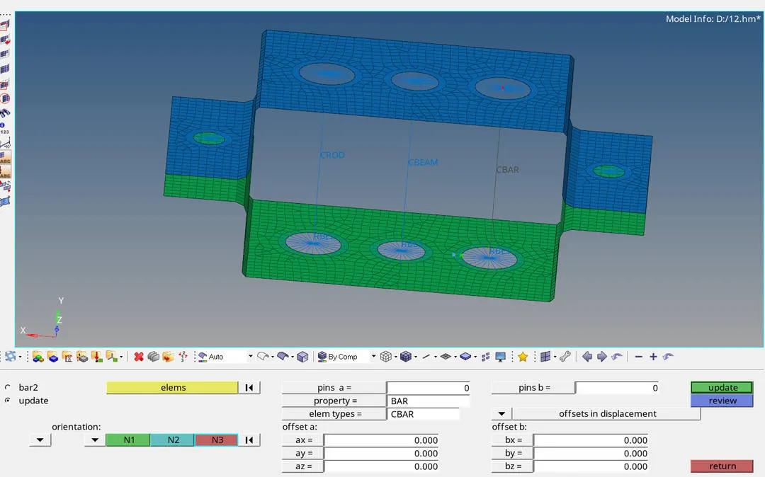
UPDATING PROPERTY OF BAR
APPLY MASSES
To apply mass on point D and E
Goto geometry page >> 1D >> Masses >> select a master node of rigit link >> Select mass value as 10 >> Elem type as CMASS 1 >> Create
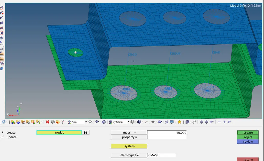
SELECTING NODE TO APPLY MASS
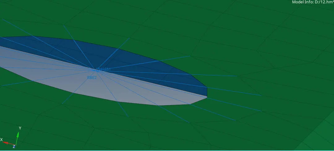
APPLIED MASS
CREATE A SPRING CONNECTION
To create a spring connection
Goto geometric page >> 1D >> Spring >> Select node 1 and node 2 >> Create
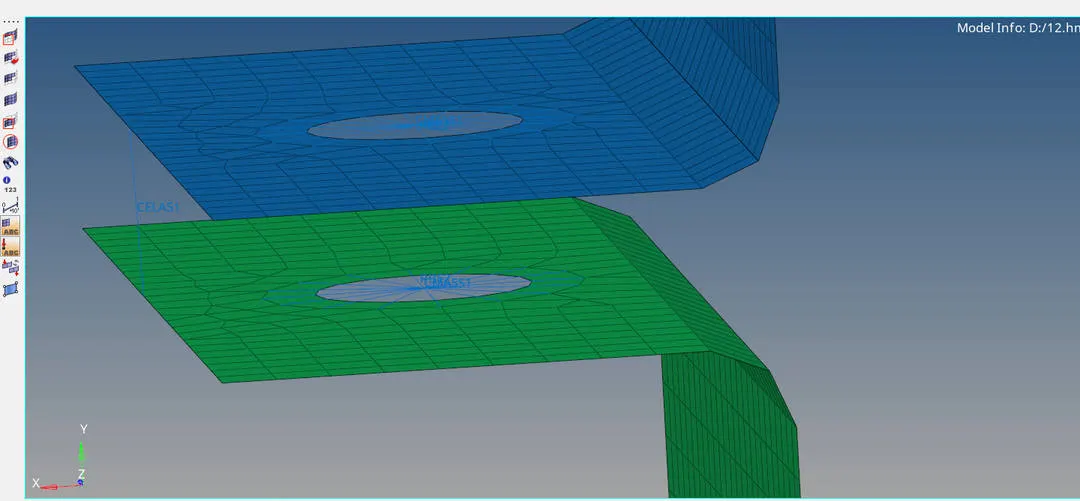
SPRING CONNECTION IS CREATED
RESULT: Created a 2D mesh and Deployed 1D elements on the given component with given cross section is done
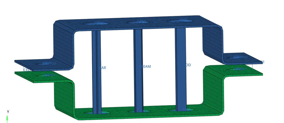
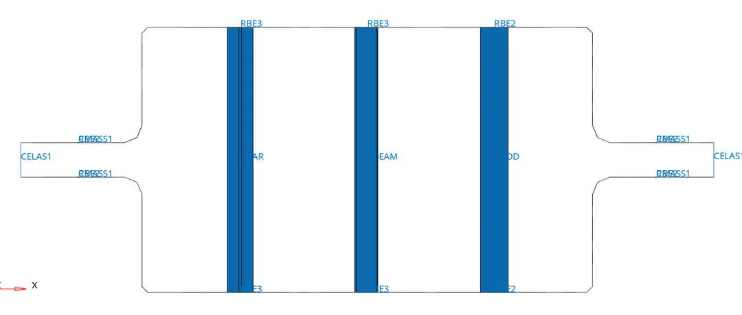
CONCLUSION: I would like to conclude that here we learned how to take mid surafce and how to create 1D elements like ROD, BEAM AND BAR