Week-4 : Basic Calibration of Single cylinder CI-Engine
Aim:
Basic calibration of single cylinder CI engine.
Objectives:
1.Compare SI vs CI and list down differences (assignment no 2-SI)
2.Comments on following parameters
- BSFC
- Exhaust Temperature
- A/F ratios
3.Change MFB 50 and observe impact on performance
SI and CI engine differences:
| S.no | Spark Ignition Engine | Compression-Ignition Engine |
|---|---|---|
| 1 | SI engines are high-speed engines. | CI engines are low-speed engines. |
| 2 | SI engines have a low thermal efficiency | CI engines have high thermal efficiency. |
| 3 | Petrol is used as fuel, which has a high self-ignition temperature. | Diesel is used as fuel, it has a low self-ignition temperature. |
| 4 | Knocking takes place at the end of combustion. | Knocking takes place at the beginning of combustion. |
| 5 | SI engine works on the otto cycle. | CI engine works on the diesel cycle. |
| 6 | The homogeneous mixture of fuel, hence high pressure is generated. | A heterogeneous mixture of fuel, hence low pressure is generated. |
| 7 | Constant volume cycle. | Constant pressure cycle. |
| 8 | Spark plug is required | Spark plug is not required. |
| 9 | No fuel pump is used | Fuel pump is used to inject fuel |
| 10 | Engines are more compact and light. | Heavier and strong engines due to higher pressure involved |
| 11 | These engines have a smooth operation | Roughness in engine operation encountered, especially when the engine runs at high speed and low loads. |
| 12 | Compression ratio is low. | Compression ratio is high |
| 13 | Less Hydrocarbon is produced. | More hydrocarbon is produced. |
| 14 | The starting of SI engine is easy. | The starting of CI engine is difficult. |
| 15 | It is used in light commercial vehicles like motorcycle, cars etc. | It is used in heavy duty vehicles likes bus, trucks, ships etc. |
BSFC:
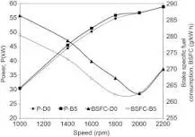
The exhuast temperature is the temperature of the gas after it leaves the combustion chamber.Exhaust gases normally discharges at a temperature of around 420°C (788°F).Diesel engine exhaust gases vary with speed and load. High loads and high speeds result in the highest temperatures. Generally, temperatures of 500–700°C (932–1293°F) are produced in the exhaust gases from diesel-cycle engines at 100% load to 200–300°C (392–572°F) with no load. Exhaust gases normally discharges at a temperature of around 420°C (788°F).
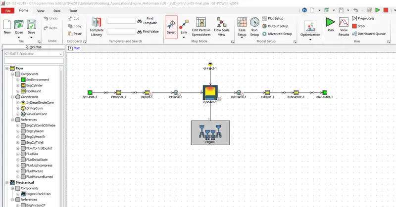
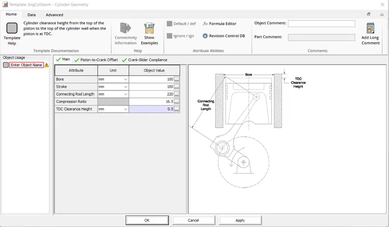
The following table summarizes the major differences in their setup
|
Component |
Parameter |
1 cylinder SI |
1 cylinder CI |
|
Env-inlet |
Pressure (bar) |
1 |
2.4 |
|
Temperature (K) |
300 |
350 |
|
|
Length (mm) |
300 |
120 |
|
|
Intake Runner |
Wall Temperature (K) |
300 |
350 |
|
Cylinder |
Bore (mm) |
86 |
100 |
|
Stroke (mm) |
86.07 |
100 |
|
|
Compression ratio |
9.5 |
16.5 |
|
|
Connecting Rod (mm) |
175 |
220 |
|
|
Clearance Height (mm) |
1 |
0.5 |
|
|
Env-outlet |
Pressure (bar) |
1 |
2.4 |
|
Temperature (K) |
300 |
350 |
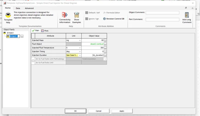
Injection duration parameters:
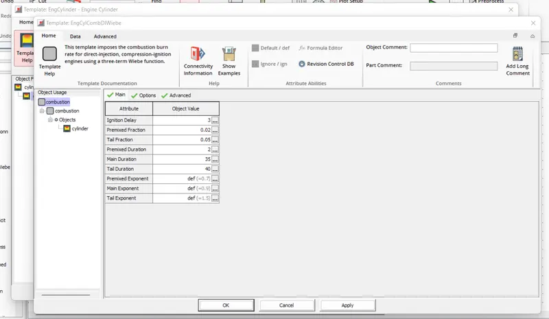
Combustion parameters:
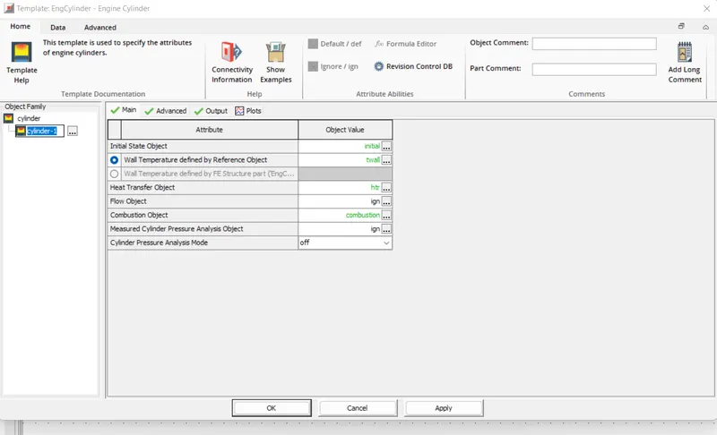
Cylinder template:
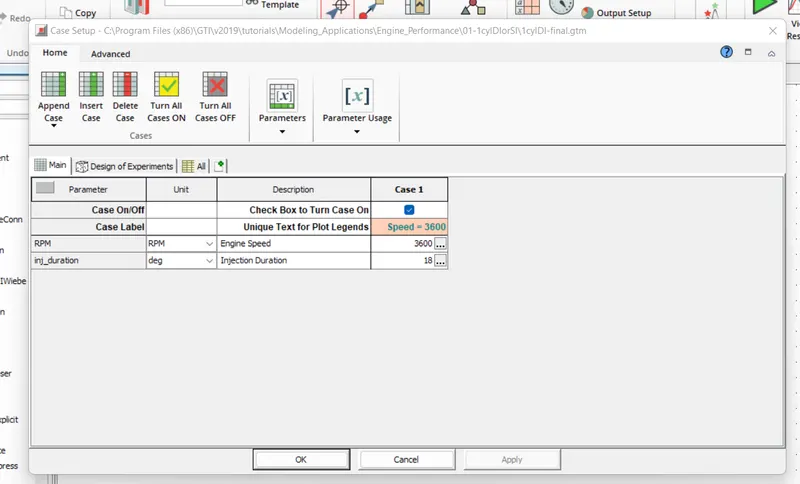
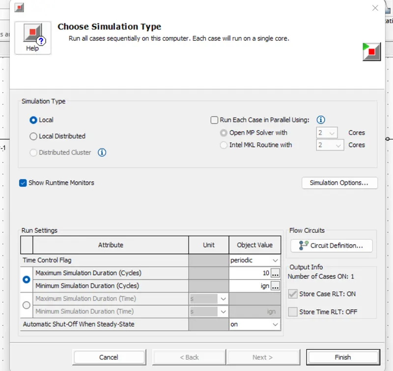
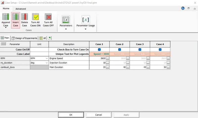
Case setup for ci engine:
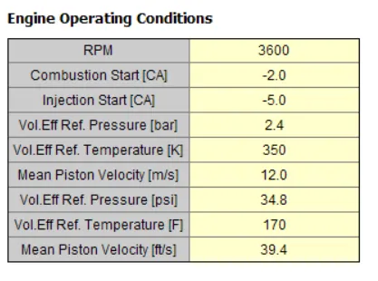
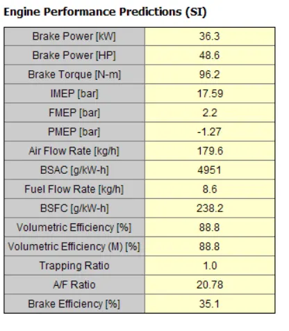
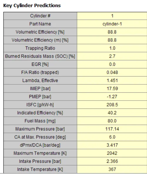
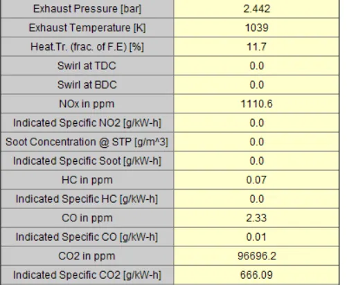
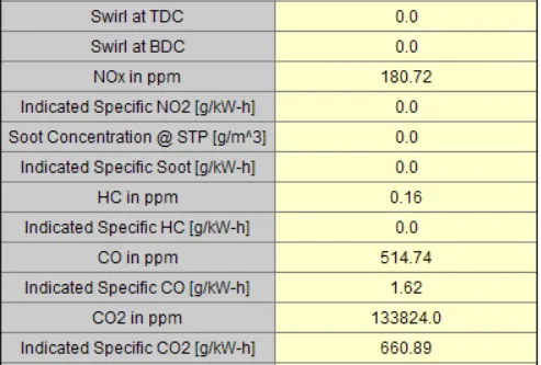
Report tables results:
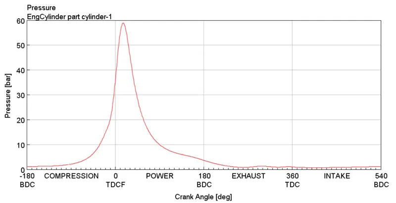
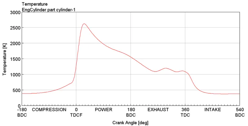
Plots:
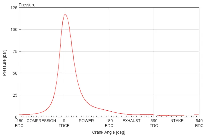
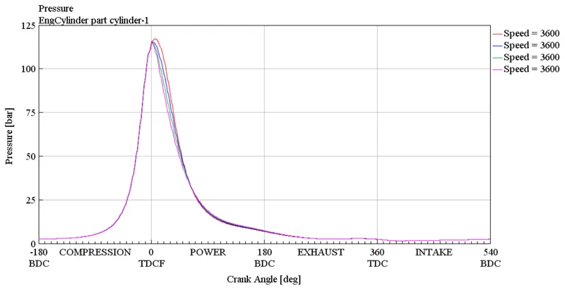
Pressure:
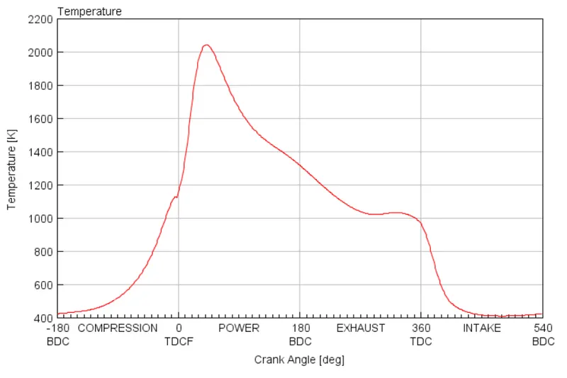
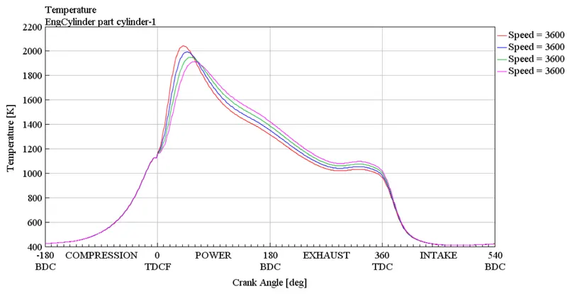
Temperature:
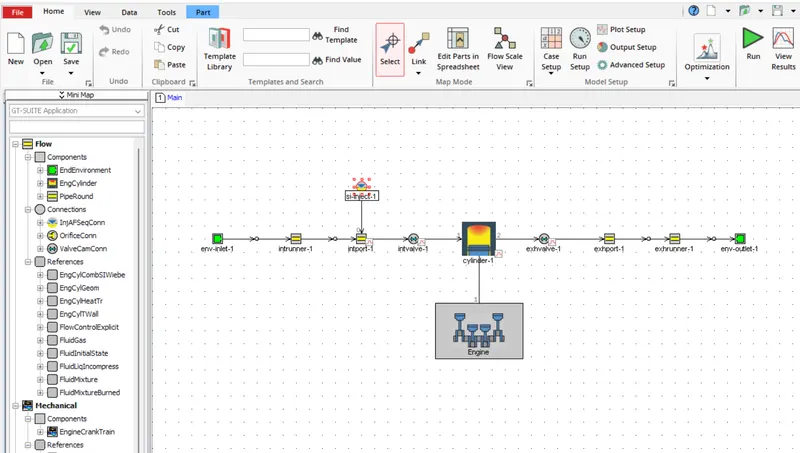
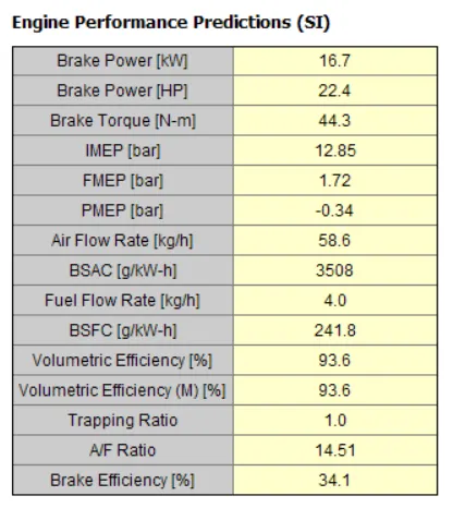
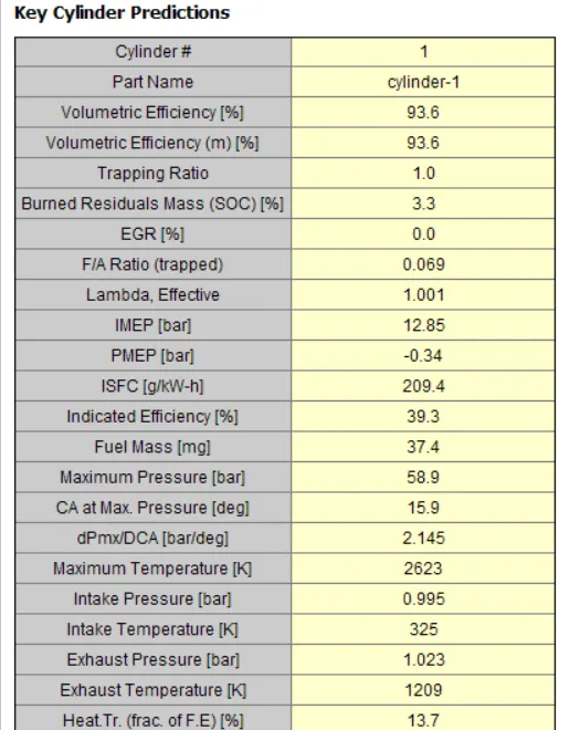
Comparing the SI engine performances:
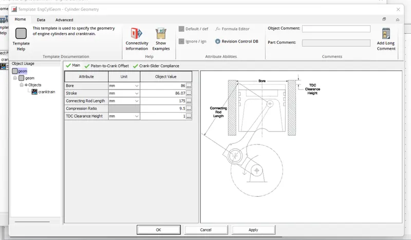
Geometry dimensions of SI engine:
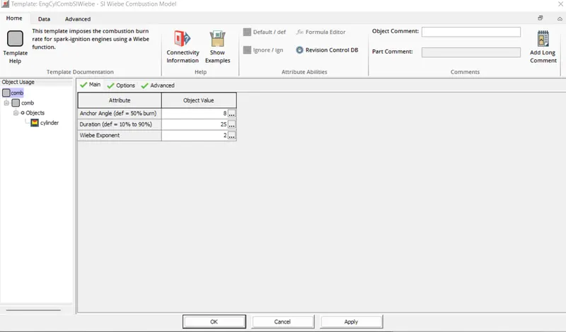
Combustionn chamber template:
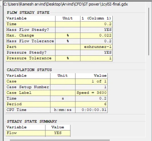
GT post:
Pressure plot:
Temperature plot:
Changing MFB to 50:
Append the different cases in case setup and run the simulation.
Report table:
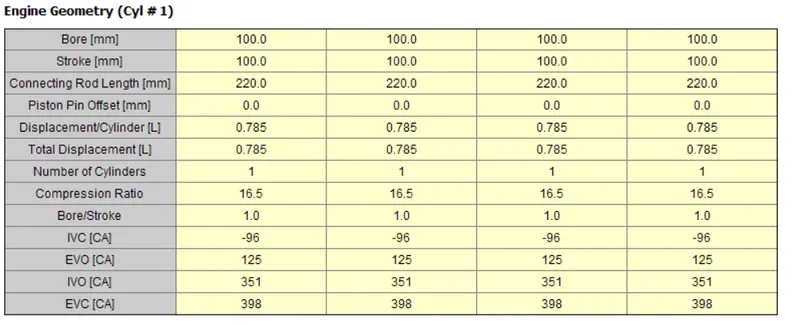
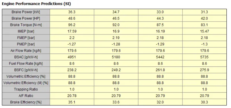
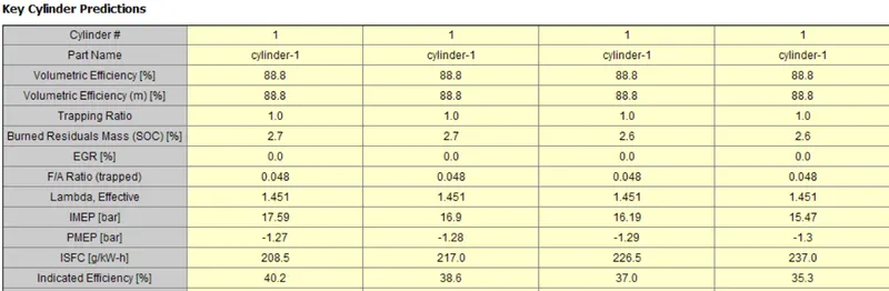
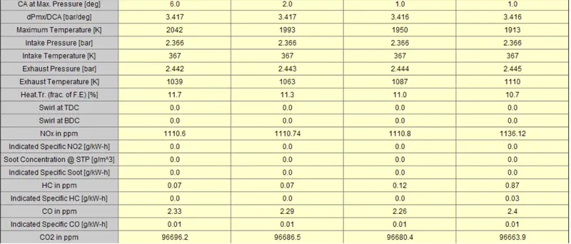
Plots:
Conclusion:
- The CI engine is successfully designed with different speeds and observe the results of the different parameters.
- Done the Comparison of the different parameters like BSFC,Air fuel Ratio,Exhaust Temperature of the SI and CI engines.
- Change the main duration time and observe the performance of the engine.