Week 8 - Simulation of a backward facing step in OpenFOAM
Aim:
- Simulate an incompressible-laminar-viscous flow through the backward facing step geometry.
- Perform transient simulation based on the described physics of flow in the problem statement.
- Explain the simulation process and way of setting the problem satement in OpenFoam and explain the changes to get the desired results.
- simulation without using any grading factor(G.F=1) and simulation with grading factor as 0.2
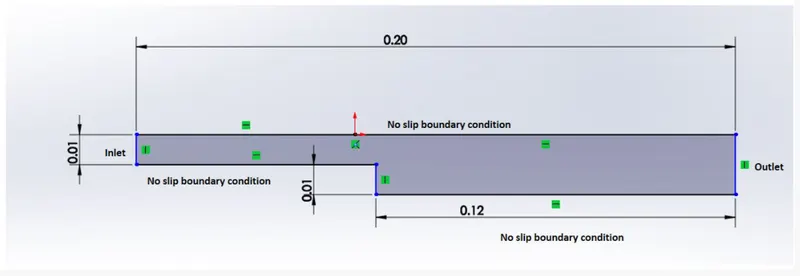
Given geometry
Steps to be done:
- Choosing a solver
- Selecting a solver tutorial to create the geometry and the mesh
- applying the boundary and initial conditions.
- post processing the results
- Plotting the results
Choosing a Solver:
Assumptions for the problem
- The fluid is Newtonian
- The flow is incompressible and laminar
- Low Reynolds number
- zero frictional losses
The solver choosen from the above assumptions is icoFoam as it solves incompressible laminar Navier stokes equation.
Block Specification:

Front an back view of the geometry: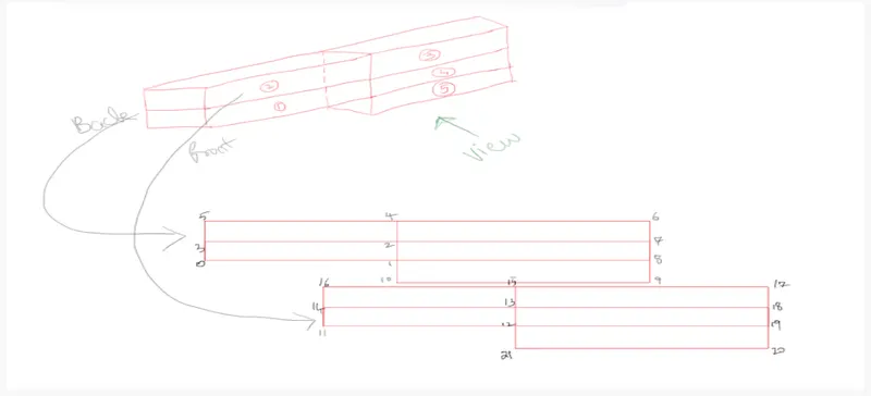
Bigger picture of the geometry:
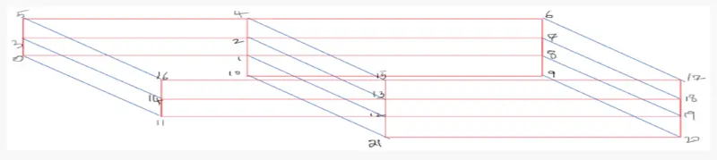
Mesh specification :
Number of cells along x direction = 200
Number of cells along y direction =10
Grading factor:
the expansion ratios enables the mesh to be graded or refined in different directions.The ratio is that of the width of the end cell along one edge of a block to the width of the start cell along the edge.
Expansion ratio =(size of end cell)/(size of sarting cell)
BlockMesh without using any grading factor(MG=1)
/*--------------------------------*- C++ -*----------------------------------*\
  =========                 |
  \\      /  F ield         | OpenFOAM: The Open Source CFD Toolbox
   \\    /   O peration     | Website:  https://openfoam.org
    \\  /    A nd           | Version:  8
     \\/     M anipulation  |
\*---------------------------------------------------------------------------*/
FoamFile
{
    version     2.0;
    format      ascii;
    class       dictionary;
    object      blockMeshDict;
}
// * * * * * * * * * * * * * * * * * * * * * * * * * * * * * * * * * * * * * //

convertToMeters 1;

vertices
(
    (0 0 0) //0
    (0.08 0 0) //1
    (0.08 0.005 0) //2
    (0 0.005 0) //3
    (0.08 0.01 0) //4
    (0 0.01 0) //5
    (0.2 0.01 0) //6
    (0.2 0.005 0) //7
    (0.2 0 0) //8
    (0.2 -0.01 0) //9
    (0.08 -0.01 0) //10
    (0 0 0.001) //11
    (0.08 0 0.001) //12
    (0.08 0.005 0.001) //13
    (0 0.005 0.001) //14
    (0.08 0.01 0.001) //15
    (0 0.01 0.001) //16
    (0.2 0.01 0.001) //17
    (0.2 0.005 0.001) //18
    (0.2 0 0.001) //19
    (0.2 -0.01 0.001) //20
    (0.08 -0.01 0.001) //21
);

blocks
(
    hex (0 1 2 3 11 12 13 14) (80 5 1) simpleGrading (1 1 1)
    hex (3 2 4 5 14 13 15 16) (80 5 1) simpleGrading (1 1 1)
    hex (2 7 6 4 13 18 17 15) (120 5 1) simpleGrading (1 1 1)
    hex (1 8 7 2 12 19 18 13) (120 5 1) simpleGrading (1 1 1)
    hex (10 9 8 1 21 20 19 12) (120 10 1) simpleGrading (1 1 1)
);

edges
(
);

boundary
(
    inlet
    {
        type patch;
        faces
        (
            (0 11 14 3)
            (3 14 16 5)
        );
    }
    outlet
    {
        type patch;
        faces
        (
            (9 8 19 20)
            (8 7 18 19)
            (7 6 17 18)
        );
    }
    frontAndBack
    {
        type empty;
        faces
        (
            (3 2 1 0)
            (5 4 2 3)
            (4 6 7 2)
            (2 7 8 1)
            (1 8 9 10)
            (13 14 11 12)
            (15 16 14 13)
            (17 15 13 18)
            (18 13 12 19)
            (19 12 21 20)
        );
    }
    fixedWalls
    {
    type wall;
    faces
    (
            (5 16 15 4)
            (0 1 12 11)
            (10 9 20 21)
            (6 4 15 17)
            (1 10 21 12)
    );
    }
);

mergePatchPairs
(
);

// ************************************************************************* //


% ControlDict file
/*--------------------------------*- C++ -*----------------------------------*\
  =========                 |
  \\      /  F ield         | OpenFOAM: The Open Source CFD Toolbox
   \\    /   O peration     | Website:  https://openfoam.org
    \\  /    A nd           | Version:  8
     \\/     M anipulation  |
\*---------------------------------------------------------------------------*/
FoamFile
{
    version     2.0;
    format      ascii;
    class       dictionary;
    location    "system";
    object      controlDict;
}
// * * * * * * * * * * * * * * * * * * * * * * * * * * * * * * * * * * * * * //

application     icoFoam;

startFrom       startTime;

startTime       0;

stopAt          endTime;

endTime         0.5;

deltaT          0.0005;

writeControl    timeStep;

writeInterval   20;

purgeWrite      0;

writeFormat     ascii;

writePrecision  6;

writeCompression off;

timeFormat      general;

timePrecision   6;

runTimeModifiable true;


// ************************************************************************* //
Boundary conditions:
Velocity for user defined faces
/*--------------------------------*- C++ -*----------------------------------*\
  =========                 |
  \\      /  F ield         | OpenFOAM: The Open Source CFD Toolbox
   \\    /   O peration     | Website:  https://openfoam.org
    \\  /    A nd           | Version:  8
     \\/     M anipulation  |
\*---------------------------------------------------------------------------*/
FoamFile
{
    version     2.0;
    format      ascii;
    class       volVectorField;
    object      U;
}
// * * * * * * * * * * * * * * * * * * * * * * * * * * * * * * * * * * * * * //

dimensions      [0 1 -1 0 0 0 0];

internalField   uniform (0 0 0);

boundaryField
{
    inlet
    {
        type            fixedValue;
        value           uniform (1 0 0);
    }

    outlet
    {
        type            zeroGradient;
    }
    fixedWalls
    {
        type            noSlip;

    }

    frontAndBack
    {
        type            empty;
    }
}

// ************************************************************************* //
Pressure conditions:
/*--------------------------------*- C++ -*----------------------------------*\
  =========                 |
  \\      /  F ield         | OpenFOAM: The Open Source CFD Toolbox
   \\    /   O peration     | Website:  https://openfoam.org
    \\  /    A nd           | Version:  8
     \\/     M anipulation  |
\*---------------------------------------------------------------------------*/
FoamFile
{
    version     2.0;
    format      ascii;
    class       volScalarField;
    object      p;
}
// * * * * * * * * * * * * * * * * * * * * * * * * * * * * * * * * * * * * * //

dimensions      [0 2 -2 0 0 0 0];

internalField   uniform 0;

boundaryField
{
    movingWall
    {
        type            zeroGradient;
    }

    fixedWalls
    {
        type            zeroGradient;
    }

    frontAndBack
    {
        type            empty;
    }
}

// ************************************************************************* //
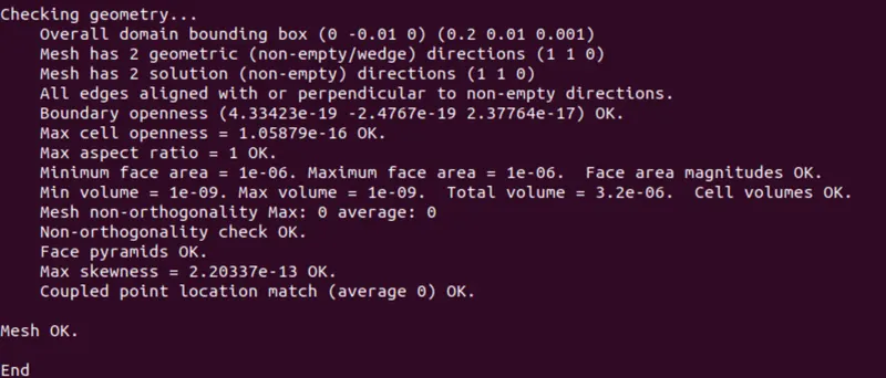
After changing the blockMeshDict ,controlDict and the boundary conditions the blockMesh command is run
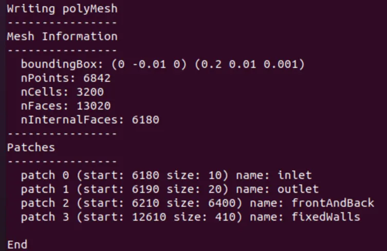
Then the checkMesh command is run to check whether the mesh is proper
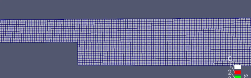
The geometry after meshing:
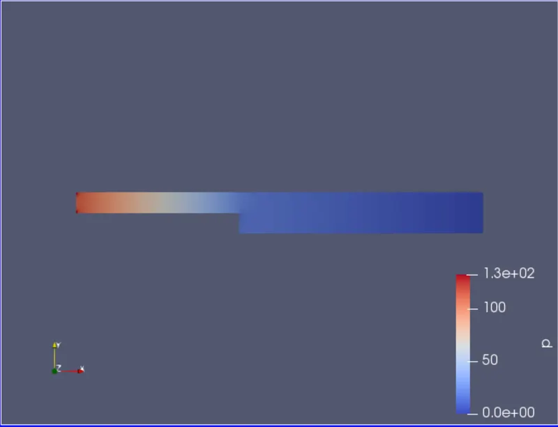
Velocity Distribution along the domain area:

Pressure distribution along the domain area:
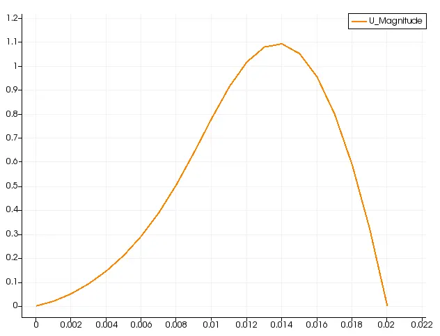
Velocity profile in the domain:
Pressure profile in the domain:
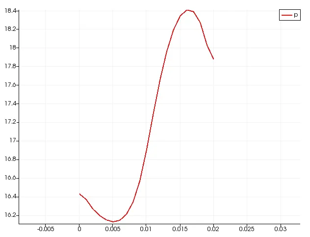
After changing the grading factor of 0.2(GF=0.2):
blockMeshDict code change for grading factor
blocks
(
    hex (0 1 2 3 11 12 13 14) (80 5 1) simpleGrading (0.2 5 1)
    hex (3 2 4 5 14 13 15 16) (80 5 1) simpleGrading (0.2 0.2 1)
    hex (2 7 6 4 13 18 17 15) (120 5 1) simpleGrading (5 0.2 1)
    hex (1 8 7 2 12 19 18 13) (120 5 1) simpleGrading (5 5 1)
    hex (10 9 8 1 21 20 19 12) (120 10 1) simpleGrading (5 5 1)
);
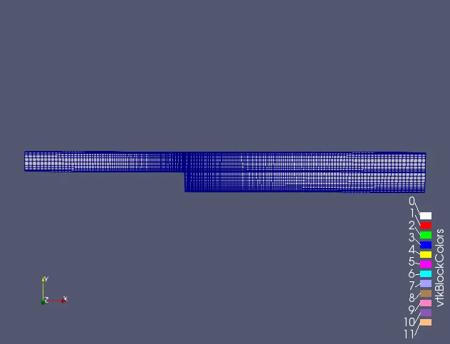
After meshing
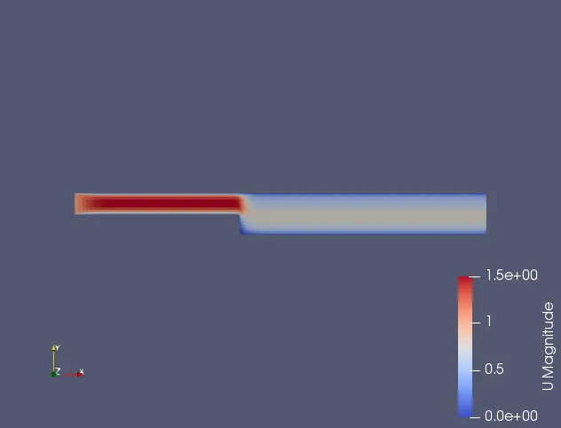
Velocity distribution along the domain:
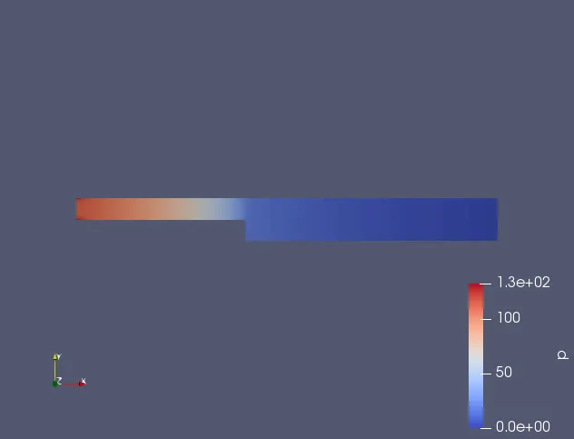
Pressure distribution along the domain:
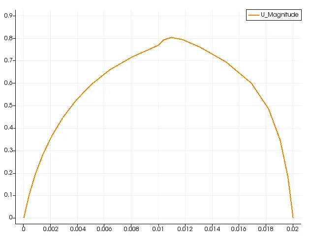
Velocity profile for MG=0.2
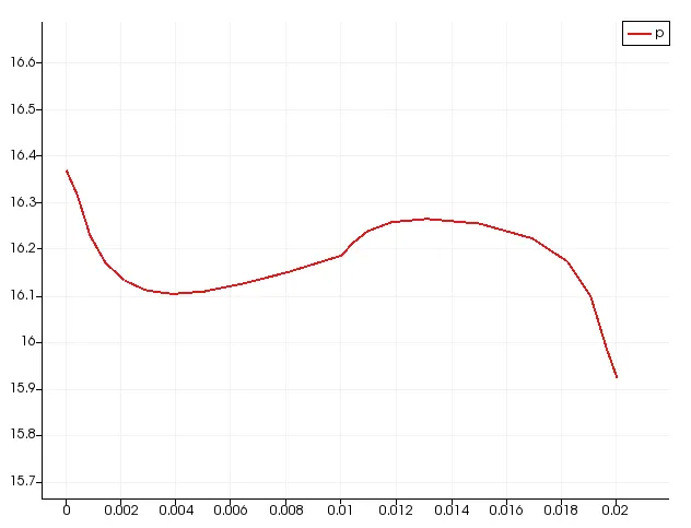
Pressure profile for GF=0.2
Procedure to be followed:
- The terminal window is opened(ctrl+alt+t) in linux OS, then the 'tut' command is used to open the OpenFoam tutorial directory and type ls to find the tutorials present in the directory.
- We solve incompressible flow and we need laminar viscous flow solver so we choose icoFoam which used as transient solver for incompressible,laminar flow of Newtonian fluids.
- Then we open the cavity folder in the icoFoam and copy the cavity folder in the FOAM_RUN directory and the run folder is opened.
- Then the cavity_test folder is opened and the system folder is opened in which the blockMeshDict files ,controlDict files are changed according to the geometry.
- 'cd ..' command is used to go one step back in the terminal window and the '0' folder is opened in which boundary conditions velocity(U) and the pressure (p) are changed accordingly to the given conditions.
- The blockMesh and checkMesh command are run to check the correctness of the block and mesh formed and icoFoam command is run to simulate the problem.
- After the simulation gets completed the parafoam command is used to open the paraview to see the visual results ,select the geometry and apply the geometry in the paraview and run the simulation once using the play button.
- Check the mesh by changing to surface with edges and select required boundary condition to see the visual change (or) results in the geometry
- Plot the graph for the given condition (i.e)0.085m from the inlet ,select the plot over line command and slect the Y-axis and provide the correct coordinate for the axis and select apply.
- And select the required parameters to bes hown in the graph in the properties box and save the screenshot using the File--> save screenshot command available in the parFoam.
- Repeat the same process for the geometry with grading factor 0.2 after changing the grading factor in the blockMeshDict file in the system folder.
Conclusion:
By calculating the Mesh grading factor,flow quantities can be calculated at desired locations.In our simulation flow quantities are calculated in more number of grid near to walls.
From the above graph it is noted that the velocity profile gets smooth near the walls.For MGF with 0.2 we can see that the projectory of the graph is smoother compared without the grading factor.MGF 0.2 velocity profile has sharper edge in the region other than the wall because of the coarse mesh in that region.
Overall the velocit and pressure magnitude profile gives similar results in general but with a mesh grading factor it is observed that the mesher can be finer near the walls and more accurate solution.