Control Logic modelling using MATLAB Stateflow®
Aim- Control Logic modelling using MATLAB Stateflow®
Objectives-
- 1. To make a model of Automatic Washing Machine by using the given conditions-
- If the power supply is available, the system gets activated
- If the Water supply is not available, stop the process & indicate through LED
- Soaking time should be 200s followed by washing time of 100s
- Then rinsing happens for next 20s & dryer runs for 50s
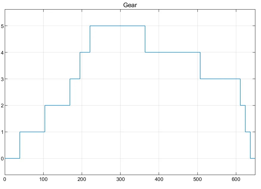
- 2. To deduce the control logic for gear shifting of an automobile based on speed profile.
- Speed(kmph) Gear
- 0 to 15 1
- 16 to 25 2
- 26 to 40 3
- 41 to 60 4
- Above 61 5
Introduction-
Stateflow® is a control logic tool used to model reactive systems by using finite state machines and flowcharts within the Simulink® environment.
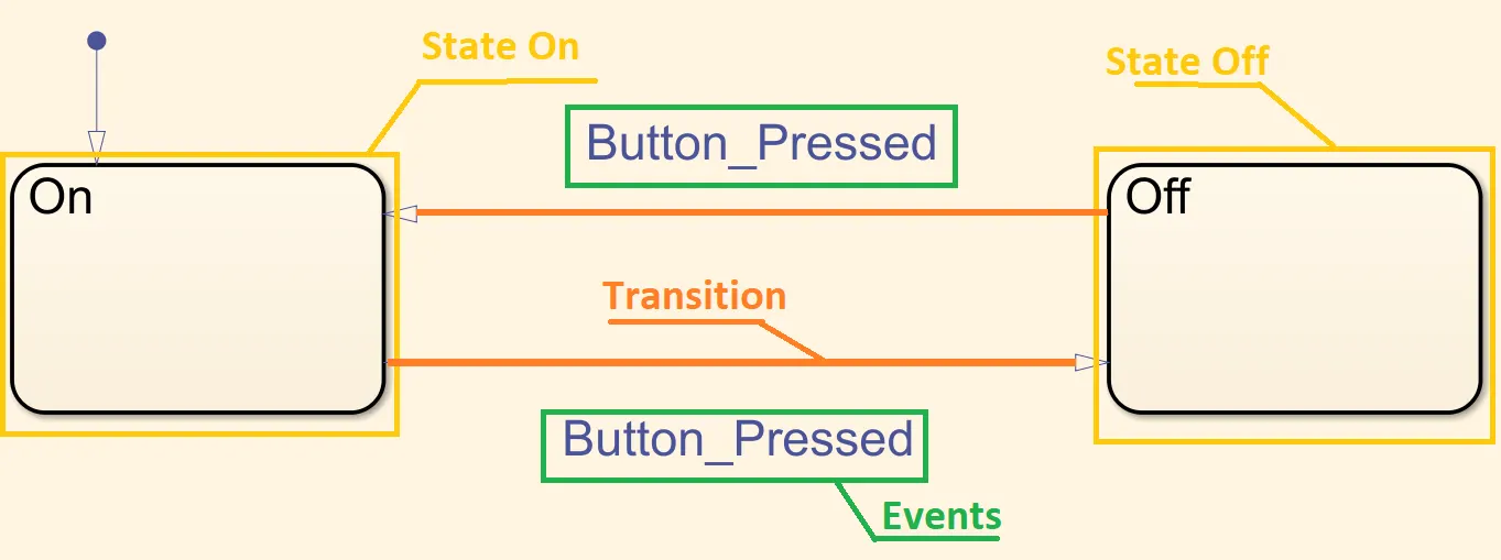
Finite State Machine is a method of modelling a system comprising limited number of modes. In Stateflow® a graphical approach is taken. State Machines can be modelled in any traditional programming language but Stateflow® is really useful as the logic gets complicated.
The basic elements of a State Machine are States, Transitions & Events.
Washing Machine Model-
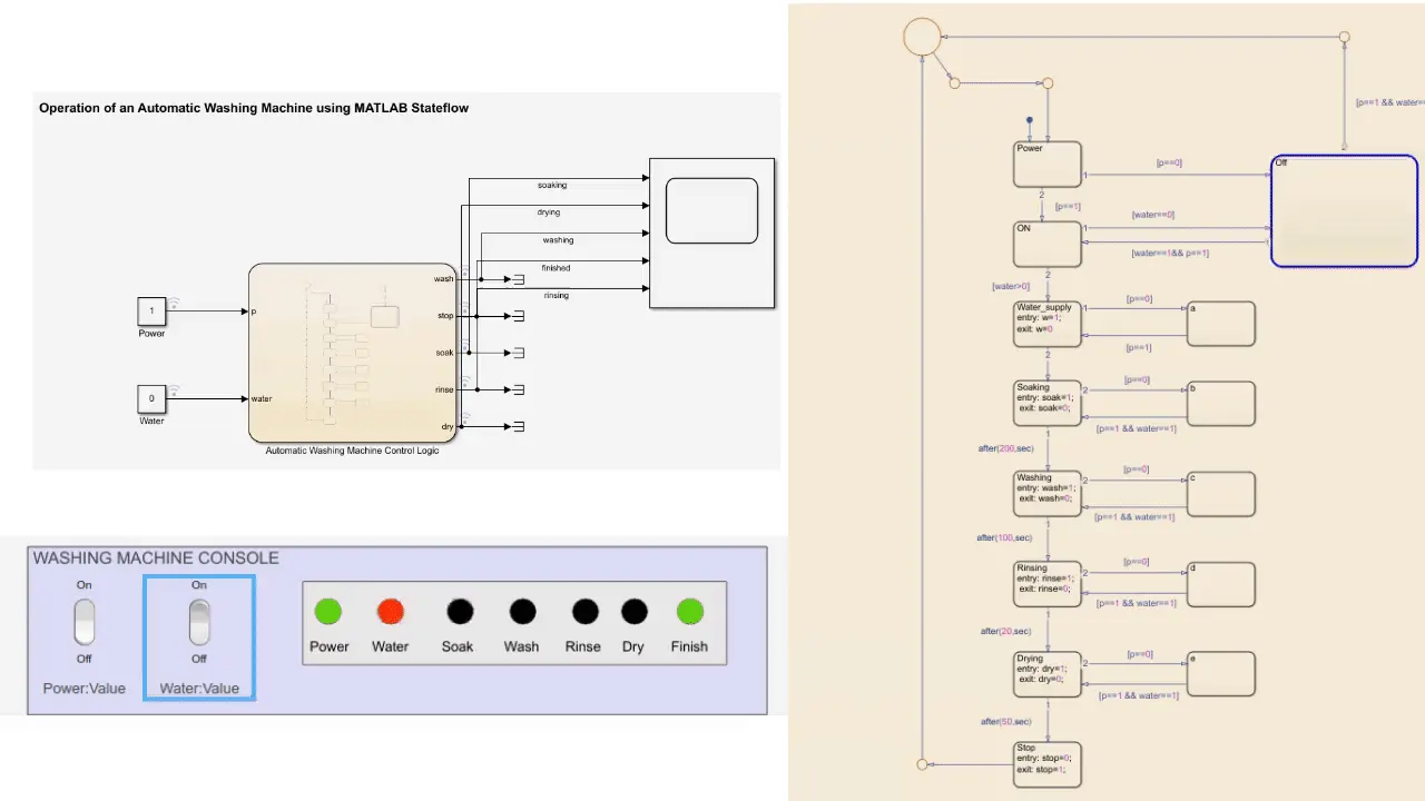
Automatic Washing Machine Model...
Stateflow® Chart-
Explanation-
Used Blocks-
|
Block |
Directory |
Use |
|
Lamp |
Simulink/Dashboard |
Displays a color indicating the value of input signal. |
|
Rocker Switch |
Simulink/Dashboard |
Toggles the value of the connected block parameter between two values during simulation. |
|
Scope |
Simulink/Sink |
Output range of input values with sample time. |
|
Terminator |
Simulink/Sink |
To cap blocks whose output ports do not connect to other blocks. |
|
Constant |
Simulink/Sources |
Generates a constant value signal. |
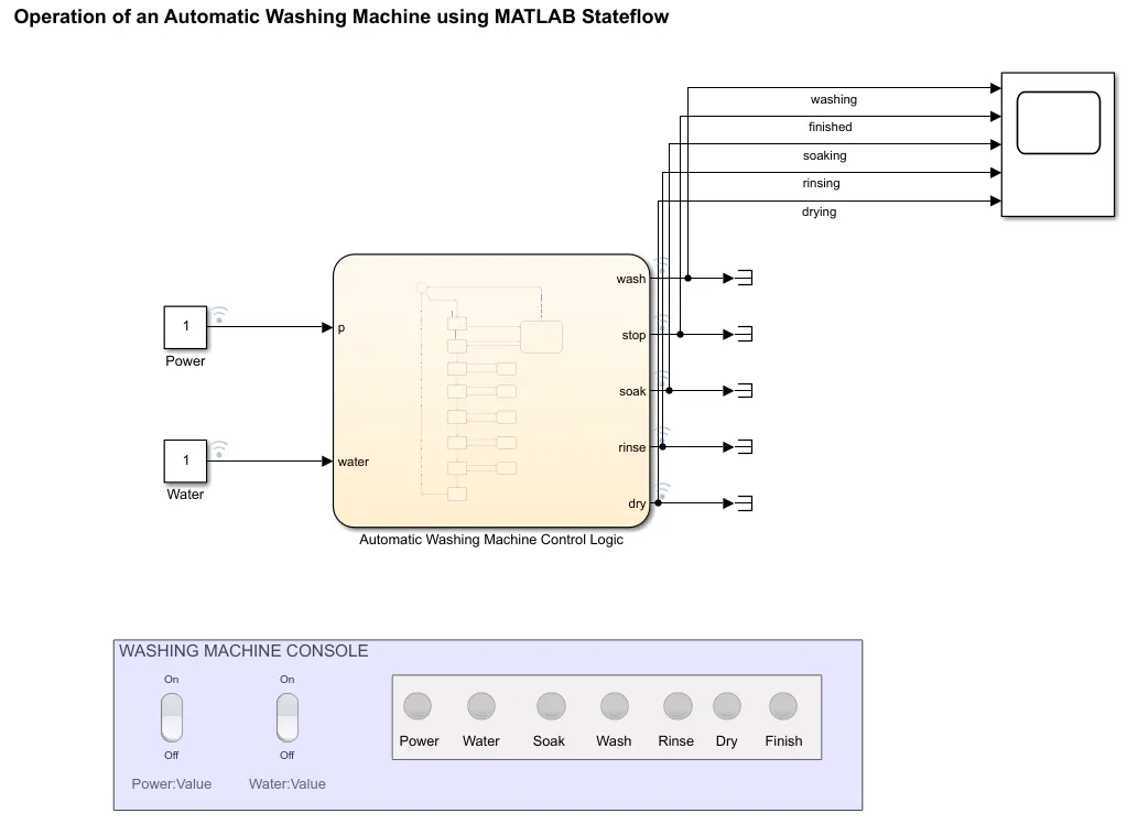
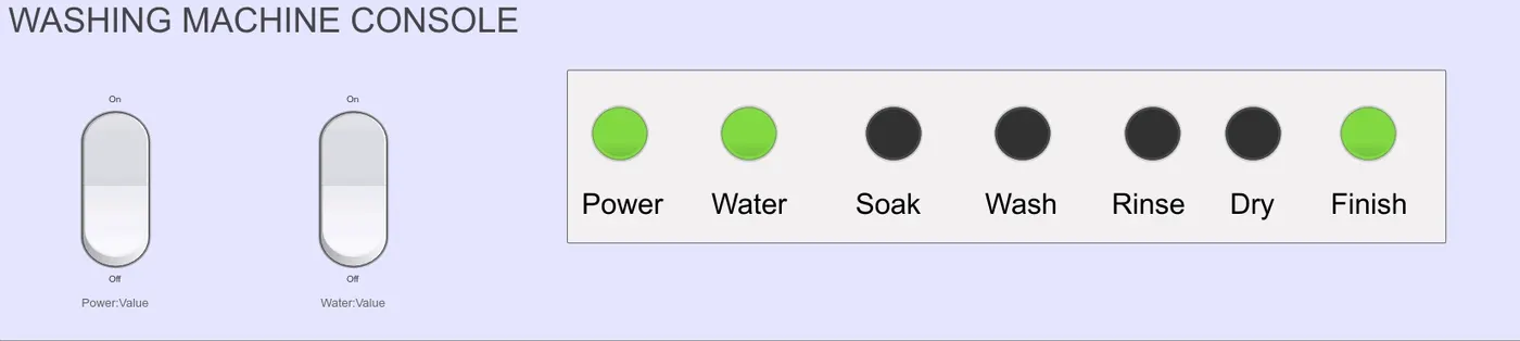
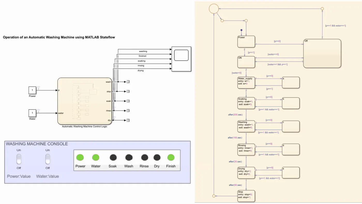
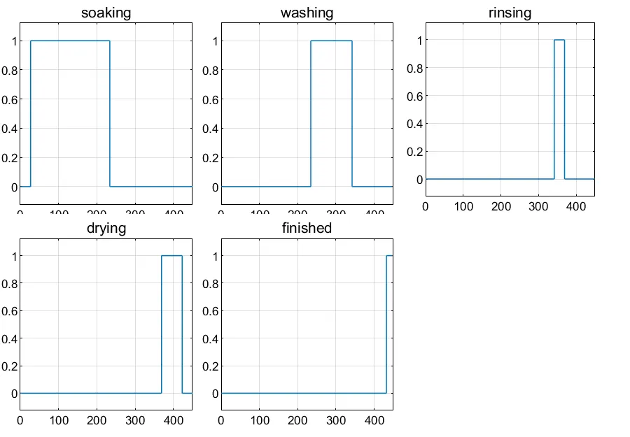
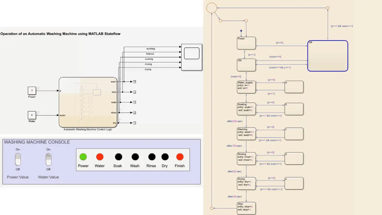
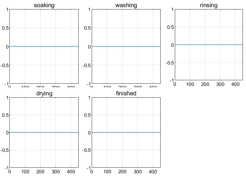
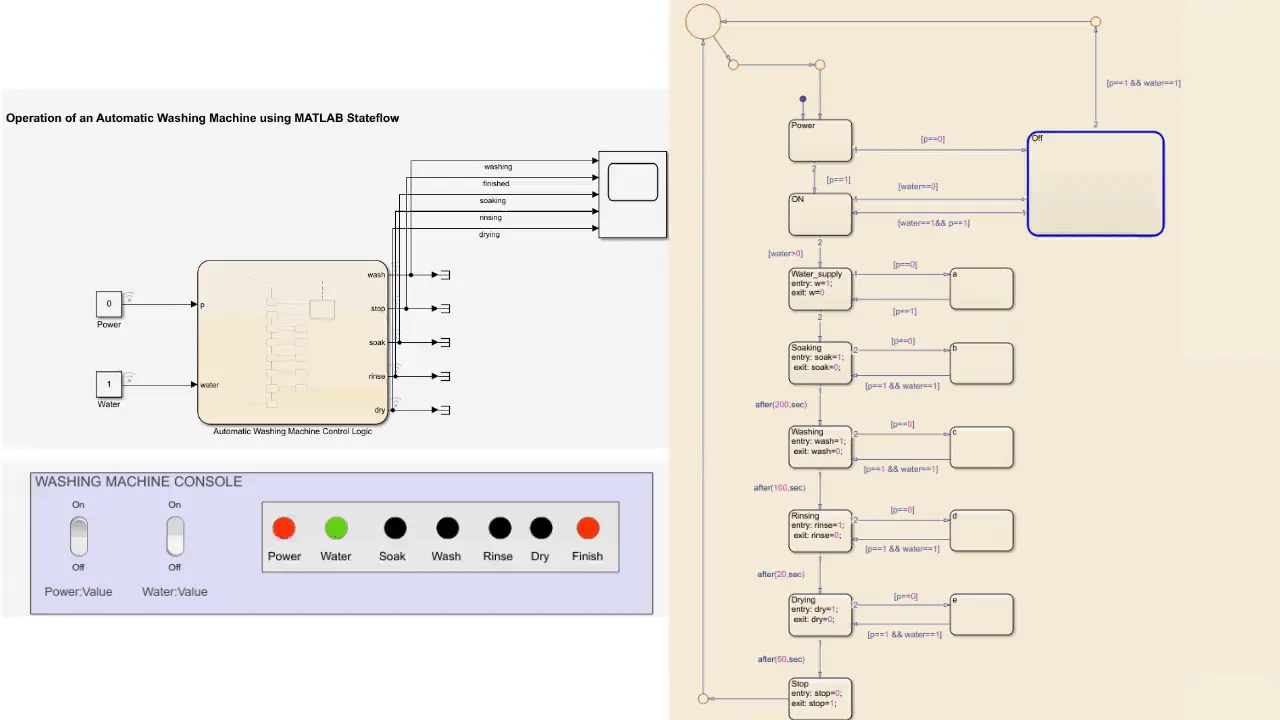
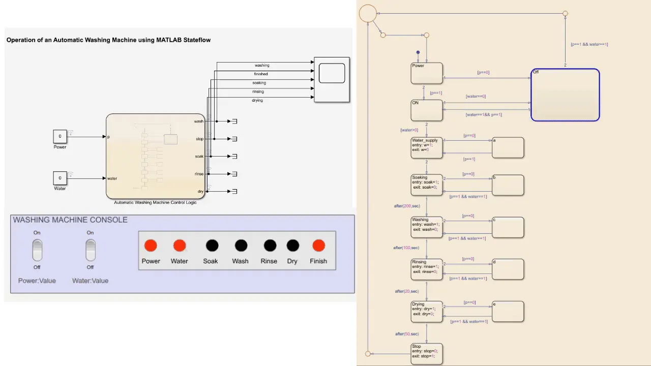
In this model, we fed the state machine with inputs of power and water availability as Boolean data (0 &1) using rocker switches and plotted the various states viz. soaking, washing, rinsing, drying in a scope and also showed the status of the washing states on the “Washing Machine Console” using lamp block.
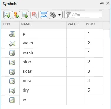
Before Simulating make sure to resolve the symbols of Stateflow® Chart using Symbols Pane in the modelling tab.
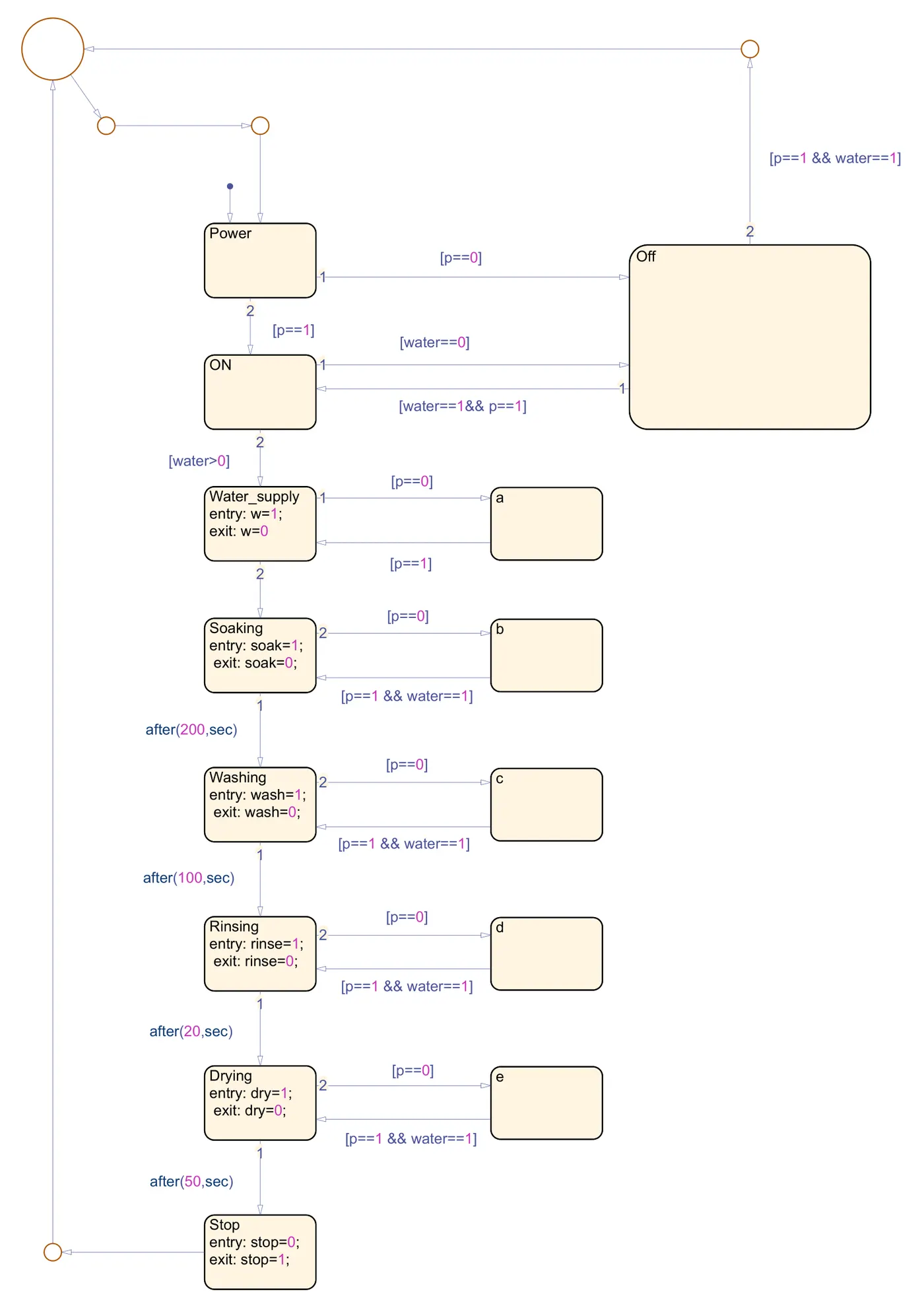
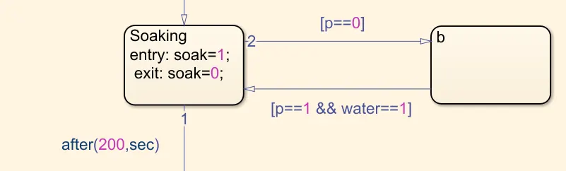
In the Stateflow® chart states a,b,c,d,e are added to make the process more robust just in case a power cut happens while the machine is operating then which state the machine should lie that is been dealt here.
Outputs-
When both power and water supply is available-
When water supply is unavailable-
When power is unavailable-
When both are unavailable-
When power supply is interrupted while machine is in operation-
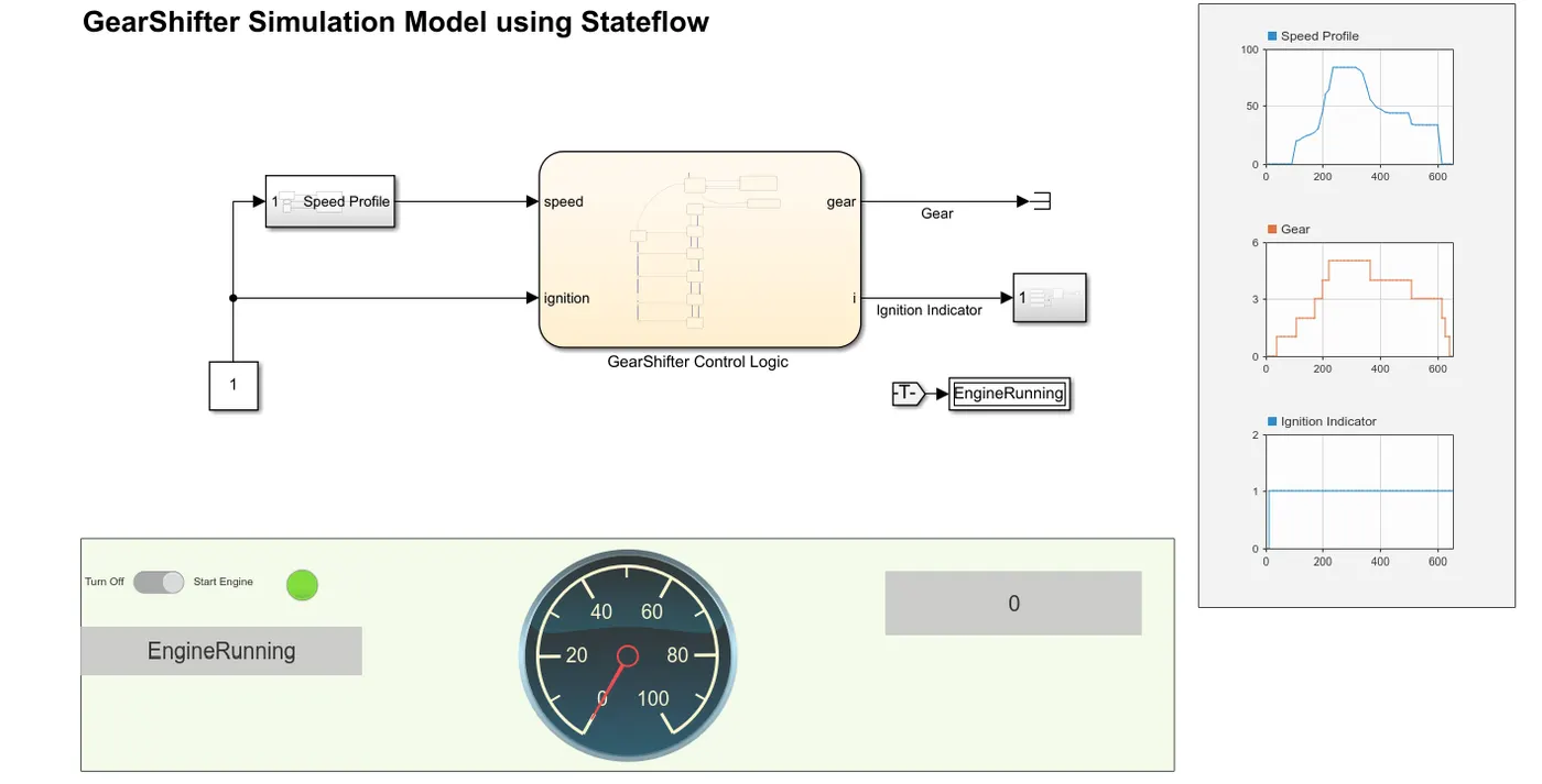
Gear Shifter Model-
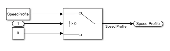
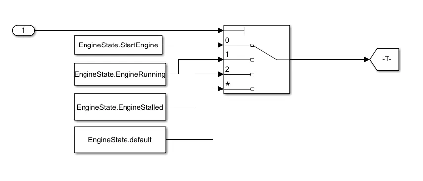
Subsystems-
Stateflow® Chart-
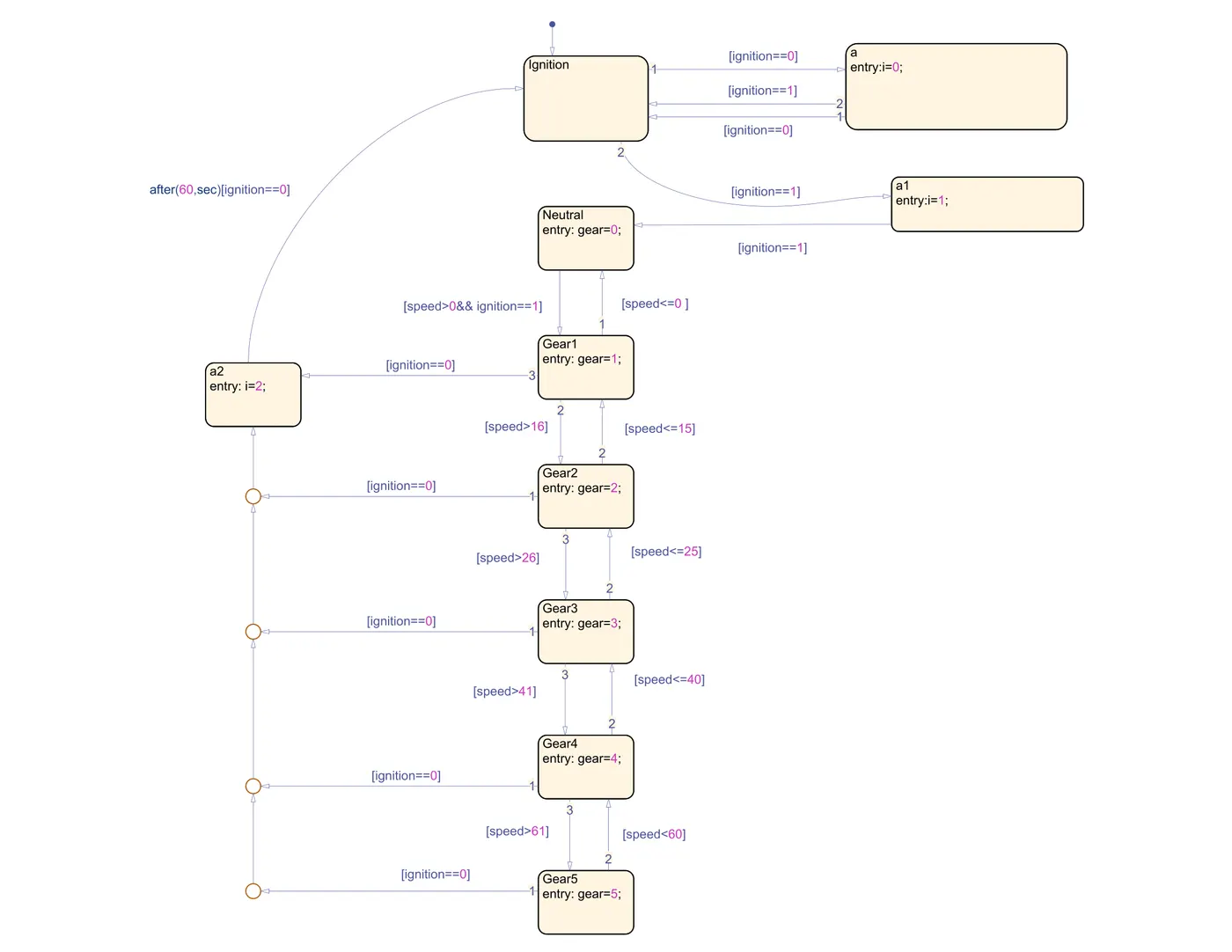
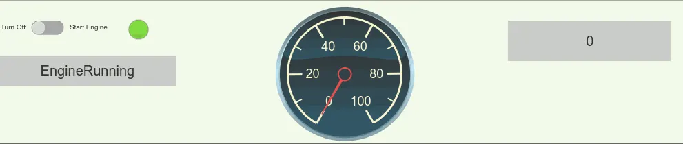
Explanation-
Used Blocks-
|
Block |
Directory |
Use |
|
Lamp |
Simulink/Dashboard |
Displays a color indicating the value of input signal. |
|
Slider Switch |
Simulink/Dashboard |
Toggles the value of the connected block parameter between two values during simulation. |
|
Dashboard Scope |
Simulink/Dashboard |
Traces signals on the dashboard during simulation. |
|
Terminator |
Simulink/Sink |
To cap blocks whose output ports do not connect to other blocks. |
|
Constant |
Simulink/Sources |
Generates a constant value signal. |
|
Custom Gauge |
Simulink/Dashboard |
Displays the value of the connected signal on a gauge face that can be customized to look like a gauge in a real system. |
|
Display |
Simulink/Dashboard |
Displays signal’s value during simulation. |
|
Goto |
Simulink/Signal Routing |
Passes its input to its corresponding From blocks. |
|
From |
Simulink/Signal Routing |
Accepts a signal from a corresponding Goto block |
|
Inport |
Simulink/Sources |
Create input port for subsystem or external input |
|
Signal Editor |
Simulink/Sources |
Display, create, edit, and switch interchangeable scenarios |
|
Switch |
Simulink/Signal Routing |
Passes through the first input or the third input signal based on the value of the second input. |
|
Multiport Switch |
Simulink/Signal Routing |
Determines which of several inputs to the block passes to the output based on the value of first input. |
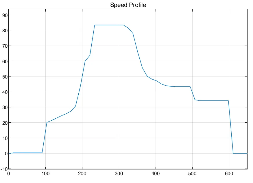
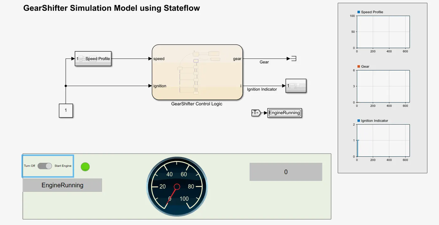
In this model gear shifting of an automobile based on the speed, to generate the speed profile Signal Editor Block is used and then that speed profile along with the ignition input is fed to the Stateflow® control logic. From the Stateflow® chart we extracted the gear and ignition indicator as outputs which are further connected the dashboard scopes.
Speed Profile Generation-
To generate the speed profile Signal Editor is used.
gearshifter_model_speed_profile.mat
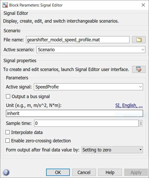
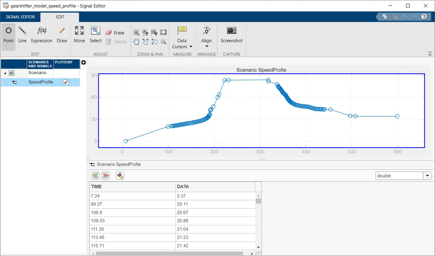
Here Enumerated data is also used to show the engine condition like whether it's off, running or stalled.
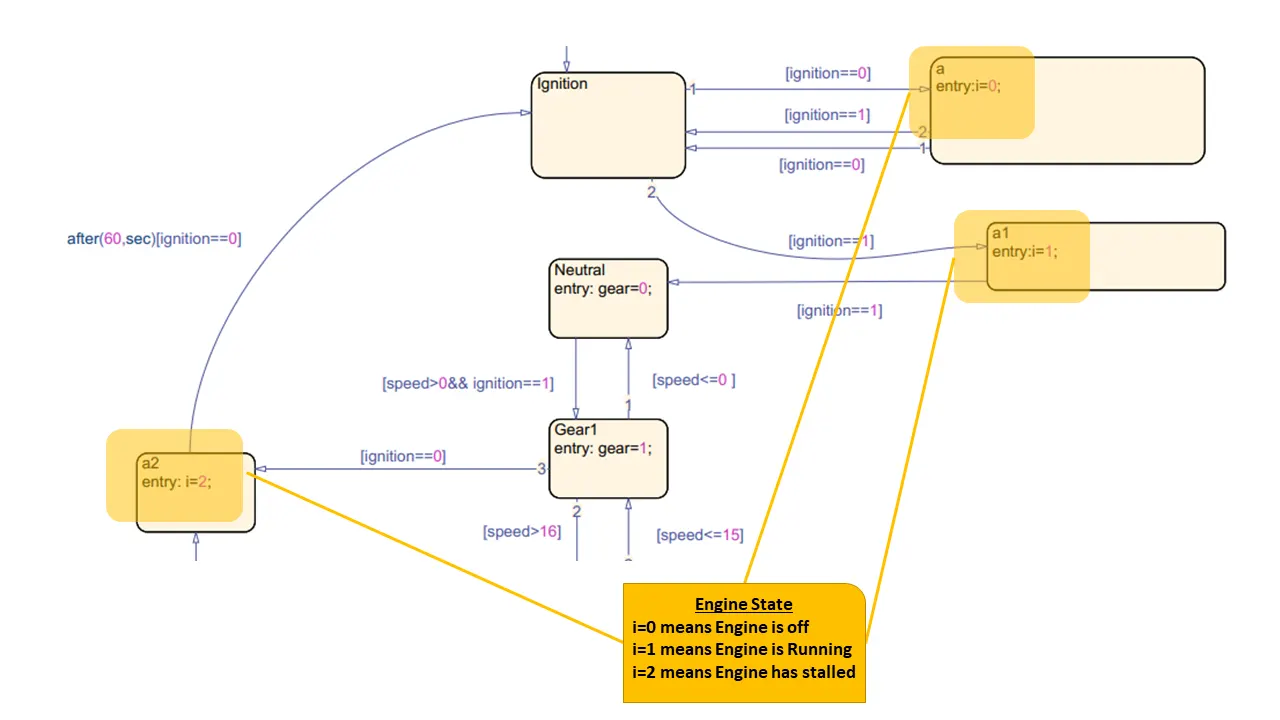
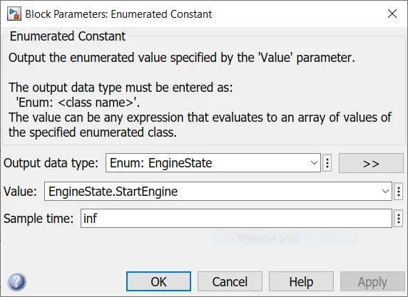
For implementing a enumerated class is created and then it is further used in Enumerated Constant block to display the engine state.
classdef (Enumeration) EngineState < Simulink.IntEnumType
  enumeration
    StartEngine(0)
    EngineRunning(1)
    EngineStalled(2)
    default(3)

  end
end 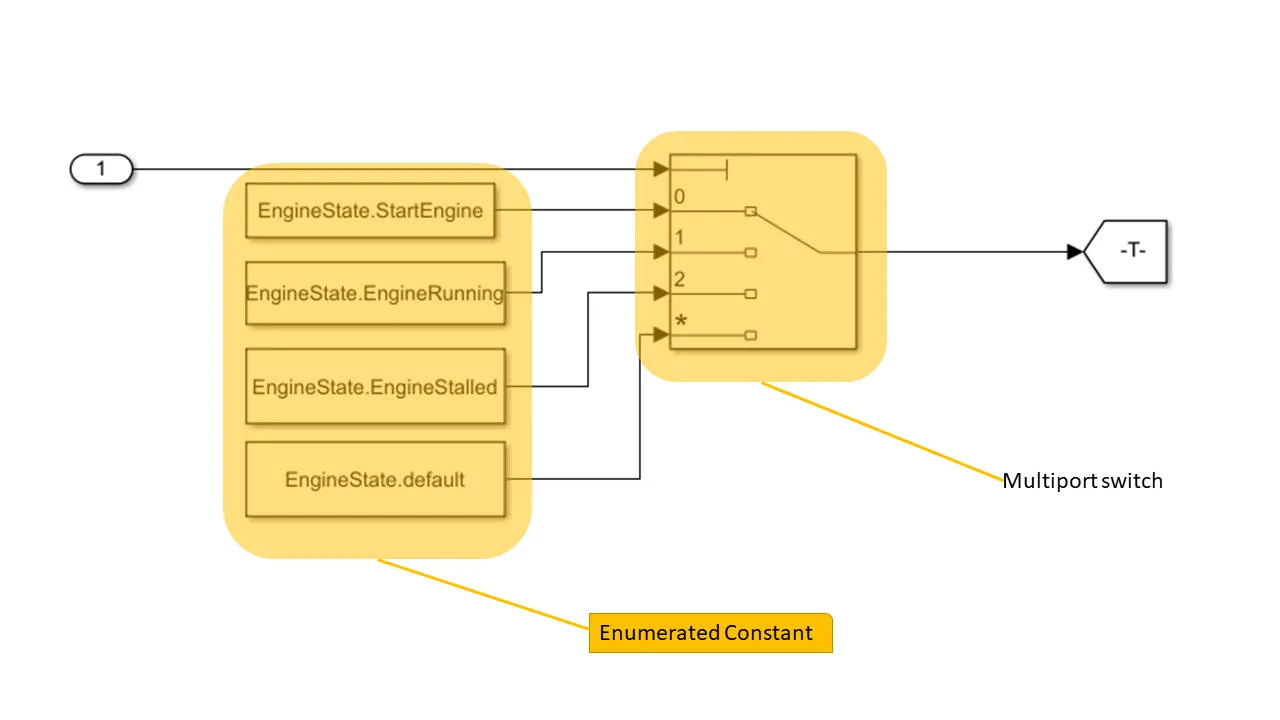
All the inputs are passed to a multiport switch which is governed by the input signal from the Stateflow® Chart.
Outputs-
Conclusion-
Thus, the concept of FSM is understood and Control logic for the FSMs viz. Washing Machine & Gear shifter is successfully modelled in Stateflow®.
References-
- https://www.mathworks.com/videos/understanding-state-machines-what-are-they-1-of-4-90488.html
- https://www.mathworks.com/help/stateflow/gs/stateflow-charts.html
- https://www.mathworks.com/help/simulink/ug/using-enumerated-data-in-simulink-models.html
- https://stackoverflow.com/questions/36688011/matlab-simulink-enumeration-mapping
- https://www.mathworks.com/help/stateflow/ug/animate-stateflow-charts.html
- https://www.mathworks.com/videos/introduction-to-stateflow-for-student-competition-teams-1507636691946.html