Week - 4
Control Logic of Gear Shifting in an Automobile and Washing Machine using Stateflow in SIMULINK
Part 1:
Control Logic of Washing Machine
Aim:
1) Implementing control logic of a “washing machine” using Stateflow as per given sequence:
- If the power supply is available, the system gets activated
- If the Water supply is not available, stop the process & indicate through LED
- The soaking time should be 200s followed by the Washing time of 100s.
- Then rinsing happens for the next 20s & the dryer runs for 50s
After all the processes have completed the finished LED is turned on
Theory:
Working of a Washing Machine:
The working principle of a washing machine is centrifugation. Centrifugation is a separation process that uses the action of centrifugal force to promote accelerated settling of particles in a solid-liquid mixture. The washing machine consists of a centrifuge for this purpose. A centrifuge is a piece of equipment that puts an object in rotation around a fixed axis, applying a force perpendicular to the axis of spin that can be very strong. A domestic Washing Machine works like an electromechanical system in which there are four processes namely:
1) Soaking
2) Washing
3) Rinsing
4) Spinning
All the 4 processes occur according to the timing that has fault given in the system. When we
also, provide water supply so that the water will be used for the above processes to wash the clothes.
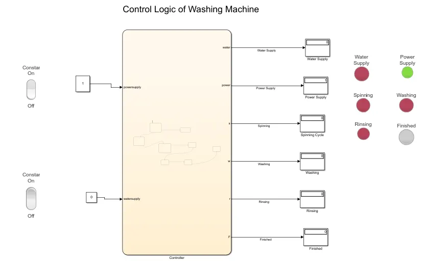
Model: when power is not supplied and water is ready
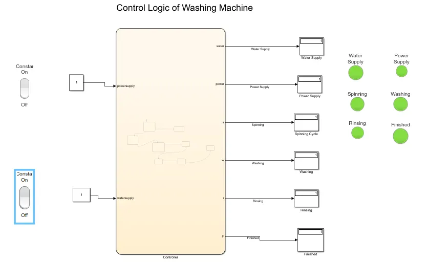
Model when there is both water and power supply:
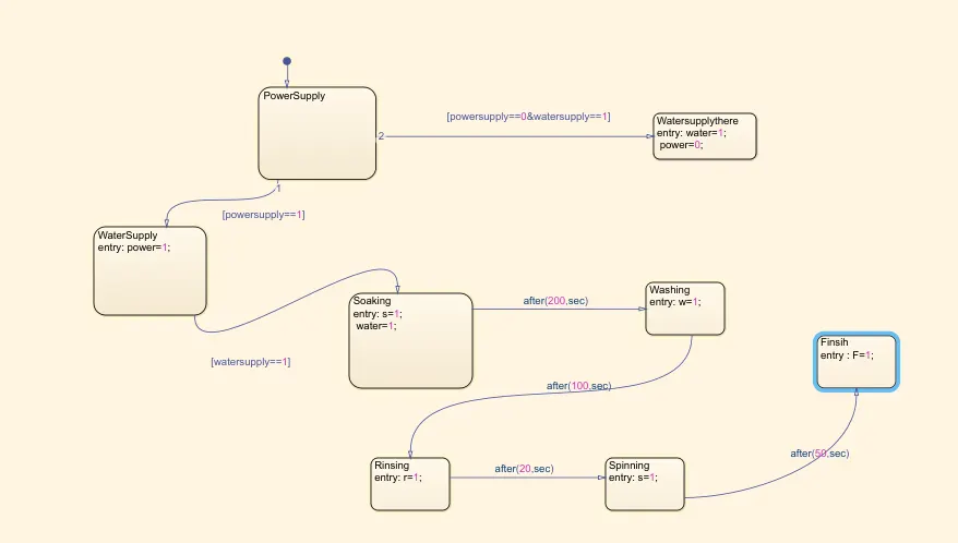
Controller Stateflow model:
Control Logic of a Washing Machine:
1) First, we open a Simulink Stateflow chart in the Simulink environment. Then in the chart, we first provide the input power supply and water supply as a flow chart. In the below image if input power and water are <1 there is zero input or no input. If the input power and water supply are >0 then there is an input provided for running the washing machine.
2) After providing the input, we then start the processes Soaking which will last for 200 secs, Washing which will last for 100 secs, Rinsing will last for 20 secs, and finally the drying process which lasts for 50 secs. Then the whole process is completed. Here in the image at the entry of each block we provide entry as 0 and exit as 1 since at entry, there is no ongoing process and at the exit, there is a process which completed.
3) After finishing the process of the flow chart we name the input and output variables according to the order of process using the symbol pane which is situated under the prepare tool strip.
4) We, then come out of the chart and give the inputs as constant blocks as there are only 2 inputs namely power supply and water supply. After that, we display the output using the display block which is the power supply, water supply, soaking process, the washing process, rinsing process, drying process, and the finishing process. We then create lamps from the Simulink library dashboard for all the outputs formed. Then we run the program for 400 secs and observe that all processes are completed successfully and output is displayed as green light glowing for all the processes.
5) When we provide zero input for the water supply or power supply the operation is not completed as the whole process uses both water and power as a source of input if either of this is missing then the output lamp turns red.
Output:
The above figures show the Simulink model and control logic of a washing machine which operates according to the power and water supply inputs. It consists of constants, charts, displays, and conditions assigned by the state block.
Case 1
When both power and water supply are on since both power and water supply are turned on which is indicated by lamps all the operations are executed and represented by corresponding lamps shows a green light.
Case 2 and vice-versa
When power is on and water is off. In this case, the machine gets a power supply but doesn't execute any of the operations since the water supply is turned off.
Looking at the lamp indicators user can easily see whether the water supply is not connected(red water supply light) or whether the power supply is not there(red power supply light) when the machine is not running.
RESULT:- The washing machine logic is successfully implemented and executed.
Part 2:
Gear Shift Logic of an Automobile
Make a Simulink chart for the “Gear shift” logic as per the below conditions:
Speed Range(km/h) Gear
0 to 15 1
16 to 25 2
26 to 40 3
41 to 60 4
Above 61 5
GEAR SHIFT:
A manual transmission, also known as a manual gearbox, a standard transmission or colloquially in some countries (e.g. the United States) as a stick shift, is a type of transmission used in motor vehicle applications. It uses a driver-operated clutch, usually engaged and disengaged by a foot pedal or hand lever, for regulating torque transfer from the engine to the transmission; and a gear selector that can be operated by hand.
A conventional 4- or 5-speed manual transmission is often the standard equipment in a modern base model vehicle, with 4-speed being more common in non-passenger vehicles such as pickup trucks and light commercial vehicles. Higher-end vehicles, such as sports cars and luxury cars are often usually equipped with a 6-speed transmission for the base model.
SIMULINK MODEL:
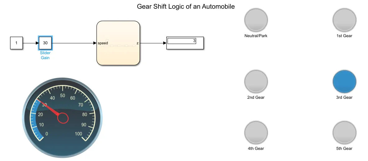
- In this model, inputs are generated to slider gain which is connected to constant block the value is 1. The gear shift is acted by conditions in Stateflow. A chart is created and conditions are applied the same as washing machine Stateflow.
- The gear is shited by variations in speed. A speed range is created in the chart as many gear systems and conditions are applied.
- A display block is used to obtain the result. That displays which gear is running in a particular range of speed.
- A lamp is connected to indicate the 5 different colors which are assigned for each gear and Neutral/Park. The model is shown below,
Model:
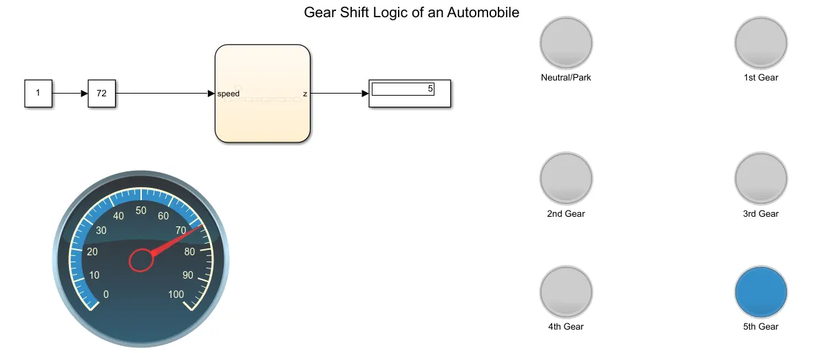
Speed=30km/h, Gear 3:
Similarly for Neutral/Park:
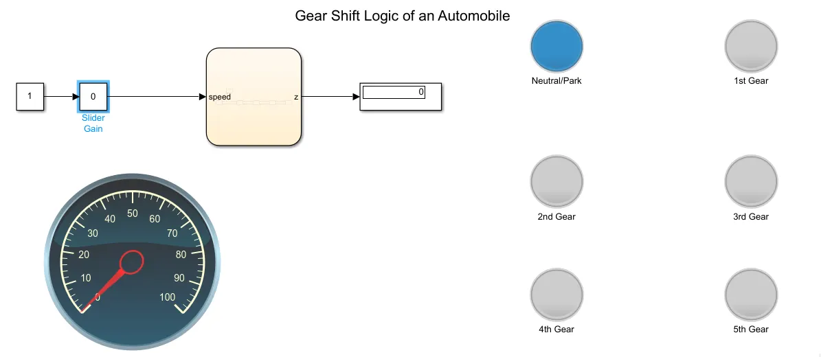
Neutral or Park condition is created by me because in automatic cars the driver tends to let go of the brake pedal during long signals or while waiting and may cause engaging of the clutch, and just cause tremendous wear since the engine keeps on running, so the park gear is usually engaged during a stop to avoid this.
Shifts Controller:
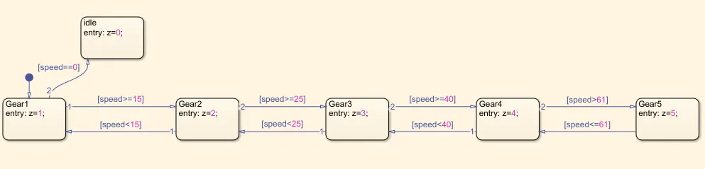
1) In the above control logic first, the default transition is dragged from the browser menu.
2) Five Gear state is created with state condition of Gear (z) 1,2,3,4 & 5 respectively and their transition is connected with speed range condition as shown in the image.
3) The transition conditions for the gear shift is decided as
Speed>15 shift to z=2
Speed>25 shift to z=3
Speed>40 shift to z=4
Speed>60 shift to Z=5 when the speed is increasing from 0-61 Kmph
similarly in the reverse direction
Speed<60 shift to z=4
Speed<40 shift to z=3
Speed<25 shift to z=2
Speed<15 shift to z=1 when the speed is decreasing from 61-0 Kmph
Symbol Pane:
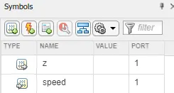
Here Speed is input and z is the Output.
Google drive link:
https://drive.google.com/file/d/1lS0JHkgbDE2juC1XYaLXTBs1ULfUcMxz/view?usp=sharing
https://drive.google.com/file/d/1BCg3vUPr65NQyk2_f0Jfxv9oi3_-TQ_n/view?usp=sharing
Conclusion:
1) We have implemented the control logic of a “washing machine” using Stateflow using the sequence provided in the aim and after finishing all the processes the LED light turns green indicating that the process is finished.
2) We have also made a Simulink chart for the “Gear shift” logic as per the information provided in the aim and for the given speed input using the slider gain block while the simulation is running, the corresponding gear number is displayed as output in the display block.